Transcription
aero 2-IOMaero 2 ACTUATOR - INSTALLATION, OPERATION & MAINTENANCE MANUALIMPORTANT SAFETY WARNINGSA. Before carrying out any repair or maintenance on the actuator, make sure that the pressure supply lines andelectrical connections have been safely isolated, removed or disconnected by authorized personnel. The actuatormust not be pressurized at any time during installation as injury may result.B. Never put any part of your body in the opening or port of the controlled valve or device.C. Special attention and precautions should be observed of the stored energy contained in the spring returnpneumatic actuators. Do not disassemble individual spring cartridges. Disassembly may result in personal injury.D. Before installing onto a valve make sure that the rotation of the valve and the actuator are the same and thatthe position indicator orientation is also correct.E. For correct operation, a pneumatic actuator must be sized adequately and with sufficient safety margin oftorque output for the correct operating conditions of the valve.*Authorized and skilled personnel should only perform maintenance of these actuators.GENERALThis instruction manual contains important information regarding the installation, operation, maintenance andstorage for rack and pinion pneumatic actuators. Please read these instructions carefully and save them for futurereference. It is important that only properly trained personnel disassemble or assemble the actuator.DESCRIPTION OF aero2 ACTUATORSThe Aluminum pneumatic actuator is a 90 Double acting or Spring return rack and pinion system, which hasbeen designed for the actuation of all type of 1/4 turn valves or 1/4 turn applications. The special finish of theinterior surface of the body (Ra 0.4 – 0.6 µm) together with the use of antifriction pads manufactured inmaterial of a very low coefficient of friction, mounted in the pistons, prevent metal on metal contact. SVF FlowControls, Inc. actuators enjoy a long and maintenance free life.Operating Media Clean, dry and lubricated compressed air Light hydraulic oil Natural gas Any other Inert and non corrosive gas (consult SVF)The maximum particle size must not exceed 0.001 µin (30 µm)Supply Pressure Minimum: 15 psig (1 bar) Maximum: 120 psig (8 bar)Operating Temperature Standard (Buna “N”): -4 F 176 F (-20oC 80oC) High temperature (Viton O-ring): 5 F 302 F (-15 C 150 C)NOTE: Caution: For low and high temperature service, special grease is required.High and low temperature will vary the output torque of the actuator. SVF Flow Controls, Inc. 13560 Larwin Circle, Santa Fe Springs, CA 90670 Phone: 1.800.783.7836 Fax: 562.802.3114www.SVF.net Specifications subject to change without notice Visit www.SVF.net for current data.1Document # SVF aero2 IOM - 11.03.2015
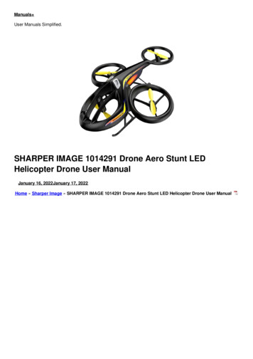
aero 2-IOMaero 2 ACTUATOR - INSTALLATION, OPERATION & MAINTENANCE MANUALLUBRICATIONThe actuator is supplied ready-lubricated no further lubrication is required. Do not operate the actuator by using flammable, oxidizing, corrosive, explosive or instable gases.Operating the actuator beyond its stated maximum operating limits of temperature, pressure orrecommend operating media, can cause personal safety risks, including death or injury, and/ordamage to internal components and to actuator housing.PRINCIPLE OF OPERATIONDouble acting actuatorSTANDARD ROTATIONA0 BREVERSE ROTATIONA B90 A0 BA B90 STANDARD ROTATION:Air to port A forces the pistons outwards, causing the pinion to turn counterclockwise while the air is beingexhausted from port B. Air to port B forces the pistons inwards, causing the pinion to turn clockwise while the airis being exhausted from port A.REVERSE ROTATION:Air to port A forces the pistons outwards, causing the pinion to turn clockwise while the air is being exhaustedfrom port B. Air to port B forces the pistons inwards, causing the pinion to turn counterclockwise while the air isbeing exhausted from port A.Spring return actuatorSTANDARD ROTATIONA0 BREVERSE ROTATIONA B90 A0 BA B90 SVF Flow Controls, Inc. 13560 Larwin Circle, Santa Fe Springs, CA 90670 Phone: 1.800.783.7836 Fax: 562.802.3114www.SVF.net Specifications subject to change without notice Visit www.SVF.net for current data.2Document # SVF aero2 IOM - 11.03.2015
aero 2-IOMaero 2 ACTUATOR - INSTALLATION, OPERATION & MAINTENANCE MANUALSTANDARD ROTATION:Air to port A forces the pistons outwards, causing the springs to compress, the pinion turns counterclockwisewhile air is being exhausted from port B. Loss of air pressure on port A, the stored energy in the springs forces thepistons inwards. The pinion turns clockwise while air is being exhausted from port A.REVERSE ROTATION:Air to port A forces the pistons outwards, causing the springs to compress, the pinion turns clockwise while air isbeing exhausted from port B. Loss of air pressure on port A, the stored energy in the springs forces the pistonsinwards. The pinion turns counterclockwise while air is being exhausted from port A.ASSEMBLY TO VALVE:Pneumatic actuators are fitted with a double square "star" pattern drive shaft and a mounting bolt patternconforming to ISO Standards. This allows the actuator to be fitted to valves in increments of 90o, allowingmounting alignment either inline or across the line of the pipe work, enabling the most efficient use of spacewithout the position affecting the actuators basic operation.Bottom of Actuator1. Fit the square of the valve directly into the square of the actuator.a. At times an insert will need to be used.2. Bolt together through the valve ISO pad.Following should be noted prior to assembly to valves: Determine the desired operation of the assembly, Normally closed valve (NC), or Normally open (NO). Check that valve and actuator are in the same position (open or closed). Check the correct positioning (alignment) of all the elements of the group, valve, coupler, bracket andactuator. Use the cross pattern method to ensure an even clamping load. Ensure all position indicators are correctly adjusted and show the correct position.IMPORTANT: When using a spring return actuator for a fail safe operation, ensure that, when air or electricityfailure occurs, the direction of rotation is correct for your application. SVF Flow Controls, Inc. 13560 Larwin Circle, Santa Fe Springs, CA 90670 Phone: 1.800.783.7836 Fax: 562.802.3114www.SVF.net Specifications subject to change without notice Visit www.SVF.net for current data.3Document # SVF aero2 IOM - 11.03.2015
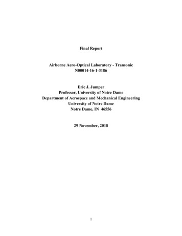
aero 2-IOMaero 2 ACTUATOR - INSTALLATION, OPERATION & MAINTENANCE MANUALMATERIALS OF 22324252627DESCRIPTIONMATERIALS SPECIFICATIONSIndicator Cap ScrewPosition IndicatorPinion Snap RingThrust WasherThrust BearingBodyPiston GuideO-Ring (Pinion Top)Bearing (Pinion Top)Inside WasherStroke Adjustment StopPinion (Drive Shaft)Bearing (Pinion Bottom)O-Ring (Pinion Bottom)Spring (Cartridge)Bearing (Piston)O-Ring (Piston)PistonPlugO-Ring (Adjust Screw)Stop Nut (Adjust Screw)Adjust ScrewStop ScrewNut (Stop Screw)O-Ring (End Cap)End CapEnd Cap ScrewPlastic/Stainless SteelPlastic (ABS)Stainless Steel 300 SeriesStainless Steel 300 SeriesPolyoxymethylene (Delrin )Extruded Aluminum AlloyPolyoxymethylene (Delrin )Buna "N" (standard), Viton Polyoxymethylene (Delrin )Polyoxymethylene (Delrin )Alloy SteelNickel Plated Alloy SteelPolyoxymethylene (Delrin )Buna "N" (standard), Viton Spring Steel (Corrosion Resistant)Polyoxymethylene (Delrin )Buna "N" (standard), Viton AluminumNBRBuna "N" (standard), Viton Stainless Steel 300 SeriesStainless Steel 300 SeriesStainless Steel 300 SeriesStainless Steel 300 SeriesBuna "N" (standard), Viton AluminumStainless Steel 300 SeriesSee Page 8 for aero2 Repair Kits SVF Flow Controls, Inc. 13560 Larwin Circle, Santa Fe Springs, CA 90670 Phone: 1.800.783.7836 Fax: 562.802.3114www.SVF.net Specifications subject to change without notice Visit www.SVF.net for current data.4Document # SVF aero2 IOM - 11.03.2015
aero 2-IOMaero 2 ACTUATOR - INSTALLATION, OPERATION & MAINTENANCE MANUALDISASSEMBLY OF THE ACTUATOR1. Safely disconnect all electric power and supply lines connected to the actuator and or accessories.2. Disassemble all the accessories of the actuator (solenoid, limit switch box, extra.)3. Disassemble the actuator off the valve.4. Remove indicator screw (#1), Lift position indicator (#2) off shaft, it may be necessary to pry gently with ascrewdriver.5. Unscrew the end caps screw (#27).Caution: When the actuator is a spring return unit, make sure that the actuator is in the failed position beforedisassembling.6. Remove stroke adjustment screw (#22) together with stop nut (#21) and O-rings (#20).7. Remove the end caps (#26).8. To rotate the pinion (#12) counterclockwise so that the pistons (#18) will exit the body (#6).Caution: Air pressure should not be used to remove the pistons from body.9. Remove the pinion snap ring (#3) and the thrust washers (#4) and thrust bearings (#5).10. Remove the pinion (#12) stroke adjustment stop (#11) and inside washer (#10) from the body of the actuator,with downward force to the top of pinion.11. Clean the components of the actuator perfectly.INSPECTION AND MAINTENANCE12. Inspect the components of the actuator for wear or damage and replace where necessary13. Replace: On the pinion: Pinion Snap Ring (#3) , O-ring (#8) and (#14) , washer (#5), Pinion bearing (#9) and (#13) On the end caps : End cap O-ring (#25) On the pistons : O-ring (#17) Piston guides (#7) Bearing (#16)All springs where fitted should be replaced during periodic maintenance.RECOMMENDED REPLACEMENT PARTS (See Page 8 for aero2 Repair Kits) PINION SNAP RING (#3) THRUST BEARING (#5) PISTON GUIDE (#7) PINION TOP O-RING (#8) PINION BEARING (#9) PINION BOTTOM BEARING (#13) PINION BOTTOM O-RING (#14) SPRING CARTRIDGE (#15) PISTON BEARING (#16) PISTON O-RING (#17) STROKE ADJUSTMENT SCREW O-RINGS (#20) END CAP O-RING (#25) SVF Flow Controls, Inc. 13560 Larwin Circle, Santa Fe Springs, CA 90670 Phone: 1.800.783.7836 Fax: 562.802.3114www.SVF.net Specifications subject to change without notice Visit www.SVF.net for current data.5Document # SVF aero2 IOM - 11.03.2015
aero 2-IOMaero 2 ACTUATOR - INSTALLATION, OPERATION & MAINTENANCE MANUALASSEMBLY OF THE ACTUATORVERY IMPORTANT before beginning the assembly check always that all the O-rings and gaskets that arecompatible with Buna and Viton rubbers are in their proper position, and all the components are greasedcorrectly using a standard commercial grease.1. Refit the pinion (#12) in the body of the actuator (#6) ensuring the stroke adjustment stop (#11) is correctly fitduring assembly. Ensure the pinion will rotate in counter-clockwise & clockwise when the stroke adjustmentscrews (#22) are refitted.2. Fit washers (#5), (#4) and pinion snap ring (#3) to the top of pinion.3. Refit the pistons (#18) in the body (#6) keeping in mind that both pistons should engage the gear of the pinion(#12) at the same time.a. For reverse rotation of the actuator refer to page 7.4. For standard rotation assembly, rotating the pinion (#12) about 40o 50o in a clockwise direction until thepistons are correctly retracted. Check that the pinion output end is square to the body and is in the correctlyaligned.Note: Obtaining the correct gear tooth and piston alignment could require more than one attempt.5. Mount the end cap (#26) to the body and tighten the screws (#27) distributing the force evenly until the endcap is securely home. Caution should be taken not to "pinch" the o-rings during this assembly procedure. In springreturn actuators, it will be necessary to insert the spring cartridges appropriately in their correct location in theend caps according to the quantity of the springs you use (see detail).5 Springs6 Springs7 Springs8 Springs9 Springs10 Springs11 Springs12 Springs6. Fit the stroke adjustment screw (#22) with the nut (#21) and o-ring (#20) in the body. SVF Flow Controls, Inc. 13560 Larwin Circle, Santa Fe Springs, CA 90670 Phone: 1.800.783.7836 Fax: 562.802.3114www.SVF.net Specifications subject to change without notice Visit www.SVF.net for current data.6Document # SVF aero2 IOM - 11.03.2015
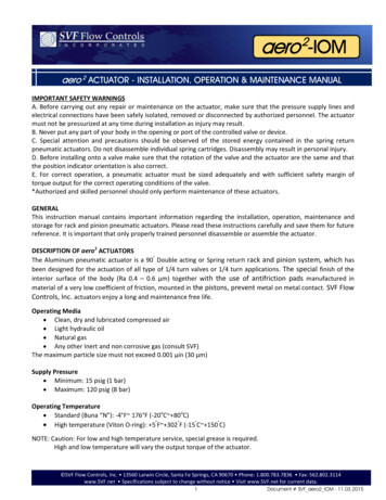
aero 2-IOMaero 2 ACTUATOR - INSTALLATION, OPERATION & MAINTENANCE MANUALReverse Rotation on aero2 ActuatorsStandard Configuration1- Air Stroke pushes pistonsoutwardwhichareengaged with the piniongear (output shaft) torotate CCW – OPEN2- SpringStrokepushespistons inward which areengaged with the piniongear (output shaft) torotate CW – CLOSED1Remove End CapsRemove Indicator Cap and use the wrench flats to assist with removal and replacement of pistons2Remove Pistons: A low (3 psi) pressure applied to port “A” will help expose the pistons for removal.Rotate pistons and re-insert. Note: Before engaging the piston (gear rack) with the pinion, “BackRotate” the pinion gear by one tooth for proper orientation.Reverse Configuration31- Air Stroke pushes pistonsoutward which are engaged withthe pinion gear (output shaft) torotate CW – CLOSED2- Spring Stroke pushes pistonsinward which are engaged withthe pinion gear (output shaft) torotate CCW – OPEN SVF Flow Controls, Inc. 13560 Larwin Circle, Santa Fe Springs, CA 90670 Phone: 1.800.783.7836 Fax: 562.802.3114www.SVF.net Specifications subject to change without notice Visit www.SVF.net for current data.7Document # SVF aero2 IOM - 11.03.2015
aero 2-IOMaero 2 ACTUATOR - INSTALLATION, OPERATION & MAINTENANCE MANUALENDSTOP ADJUSTMENT - CLOCKWISE:(Right Adjusting screw) Loosen the security nut (#21) of the right hand external stroke adjustment screw. Tighten or loosen the external stroke adjustment screw (#22) until reaching the required position. Tighten the security nut (#21) of the right hand external stroke adjustment screw.ENDSTOP ADJUSTMENT - COUNTERCLOCKWISE:(Left Adjusting screw) Loosen the security nut (#21) of the left hand external stroke adjustment screw Tighten or loosen the external stroke adjustment screw (#22) until reaching the required position. Tighten the security nut (#21) of the left hand external stroke adjustment screw.PRESSURE TEST:Pressure test the actuator with 90 psig (6 bar) compressed air and inspect for leaks using a soap and watersolution sprayed on to all joints and rotating shafts.STORAGE:To store the pneumatic actuators the following precautions are recommended: Ensure the actuator is completely dry and water free. Maintain the entrances of air passages by fitting the original or replacement plastic corks. Protect from dust, dirt and damage by packing in box or plastic bag.ALL PNEUMATIC ACTUATORS HAVE BEEN 100% FACTORY TESTED IN OPERATION & WATERTIGHTNESS ANDHAVE BEEN FITTED WITH INDIVIDUAL QUALITY CONTROL STAMPS.aero2 Repair Kit ComponentsITEMPinion Snap RingQTY1When ordering a Repair Kit for an aero2 Actuator, specifyThrust Washer1The Actuator Model Number.Thrust Bearing1Piston Guide2O-Ring (Pinion Top)1Bearing (Pinion Bottom)1Inside Washer1Bearing (Pinion Bottom)1O-Ring (Pinion Bottom)1Bearing (Piston)2O-Ring (Piston)2Plug2O-Ring (Adjust Screw)2O-Ring (End Cap)2 SVF Flow Controls, Inc. 13560 Larwin Circle, Santa Fe Springs, CA 90670 Phone: 1.800.783.7836 Fax: 562.802.3114www.SVF.net Specifications subject to change without notice Visit www.SVF.net for current data.8Document # SVF aero2 IOM - 11.03.2015
6 Document # SVF_aero2_IOM - 11.03.2015 aero 2 ACTUATOR - INSTALLATION, OPERATION & MAINTENANCE MANUAL aero 2-IOM SVF Flow Controls, Inc. 13560 Larwin Circle, Santa Fe Springs, CA 90670 Phone: 1.800.783.7836 Fax: 562.802.3114 www.SVF.net Specifications subject to change without notice Visit www.SVF.net for current data. .