Transcription
Digital Principles and DesignDonald D. GivoneUniversity at BuffaloThe State University of New YorkGrauuBoston Burr Ridge, IL Dubuque, IA Madison, Wl New York San Francisco St. LouisBangkok Bogota Caracas Kuala Lumpur Lisbon London Madrid Mexico CityMilan Montreal New Delhi Santiago Seoul Singapore Sydney Taipei Toronto
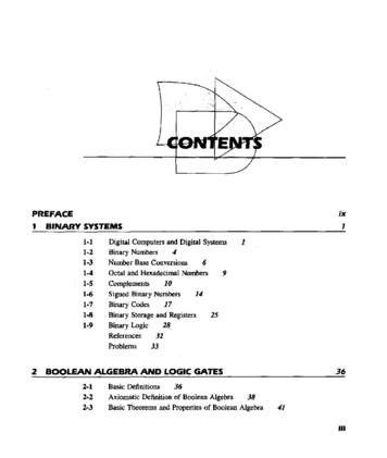
CONTENTSPreface xiii2.5.4Verification of the Iterative Methodfor Fractions 232.5.5. A Final Example 23P.haptfir 1Introduction2.61Special Conversion Procedures242.7. Signed Numbers and Complements1.1The Digital Age1.2Analog and Digital Representationsof Information 21.3The Digital Computer1.3.11.3.21.41The Organization of a DigitalComputer 3The Operation of a Digital ComputerAn Overview552.2Addition and Subtraction with (r - l ) ' s Complements 362.9.12.10 Codes2.5Signed Addition and Subtraction 3941711ProblemsIterative Method of Number Conversion-55Boolean Algebra andCombinational Networks 61Polynomial Method of NumberConversion 162.5.1 Iterative Method for ConvertingIntegers 202.5.2 Verification of the Iterative Methodfor Integers 212.5.3 Iterative Method for ConvertingFractions 22482.12 Error Correction 502.12.1 Hamming Code 512.12.2 Single-Error Correction plus Double-ErrorDetection 542.12.3 Check Sum Digits for ErrorCorrection 542.3.1 Addition 112.3.2 Subtraction 112.3.3 Multiplication 142.3.4 Division 162.4Signed Addition and Subtraction 332.11 Error DetectionCounting in a Positional NumberSystem 92.3 Basic Arithmetic Operations2.92.10.1 Decimal Codes 412.10.2 Unit-Distance Codes 442.10.3 Alphanumeric Codes 46Number Systems, Arithmetic,and Codes 72.1 Positional Number SystemsAddition and Subtraction with r'sComplements 312.8.12262.8193.1Definition of a Boolean Algebra623.1.1 Principle of Duality 633.2Boolean Algebra Theorems3.3A Two-Valued Boolean Algebra70Boolean Formulas and Functions733.4633.4.1 Normal Formulas 75vii
viii3.5DIGITAL PRINCIPLES AND DESIGNCanonical Formulas 76Chapter A3.5.1 Minterm Canonical Formulas 763.5.2 m-Notation 783.5.3 Maxterm Canonical Formulas 803.5.4 M-Notation 81Simplification of BooleanExpressions 1273.6 Manipulations of Boolean Formulas 833.6.1 Equation Complementation 833.6.2 Expansion about a Variable 843.6.3 Equation Simplification 843.6.4 The Reduction Theorems 863.6.5 Minterm Canonical Formulas 873.6.6 Maxterm Canonical Formulas 883.6.7 Complements of CanonicalFormulas 893.7Gates and Combinational Networks 913.7.1 Gates 923.7.23.7.33.7.43.7.53.8Combinational Networks 92Analysis Procedure 93Synthesis Procedure 94A Logic Design Example 95Incomplete Boolean Functions and Don'tCare Conditions 973.8.1 Describing Incomplete Boolean3.8.2Functions 99Don't-Care Conditions in LogicDesign 993.9 Additional Boolean Operations andGates 1013.9.1 The Nand-Function 1023.9.23.9.33.9.43.9.53.9.63.9.7The Nor-Function 103Universal Gates 103Nand-Gate Realizations 105Nor-Gate Realizations 108The Exclusive-Or-Function 111The Exclusive-Nor-Function 1133.10 Gate Properties 1133.10.13.10.23.10.33.10.4Noise Margins 115Fan-Out 116Propagation Delays 117Power Dissipation 118Problems 1184.1 Formulation of the SimplificationProblem 1274.1.1 Criteria of Minimality 1284.1.2The Simplification Problem 1294.2 Prime Implicants and Irredundant DisjunctiveExpressions 1294.2.1 Implies 1294.2.24.2.34.2.4Subsumes 130Implicants and Prime Implicants 131Irredundant Disjunctive NormalFormulas 1334.3 Prime Implicates and Irredundant ConjunctiveExpressions 1334.4 Karnaugh Maps 1354.4.1 One-Variable and Two-Variable4.4.24.4.34.4.4Maps 135Three-Variable and Four-VariableMaps 136Karnaugh Maps and CanonicalFormulas 138Product and Sum Term Representationson Karnaugh Maps 1414.5 Using Karnaugh Maps to Obtain MinimalExpressions for Complete BooleanFunctions 1454.5.1 Prime Implicants and KarnaughMaps 1454.5.2 Essential Prime Implicants 1504.5.3 "Minimal Sums 1514.5.4 Minimal Products 1554.6 Minimal Expressions of Incomplete BooleanFunctions 1574.6.1 Minimal Sums 1584.6.2Minimal Products 1594.7 Five-Variable and Six-Variable KarnaughMaps 1604.7.1 Five-Variable Maps 1604.7.2Six-Variable Maps 163
CONTENTS4.14.4 Incompletely Specified Functions 2134.14.5 Maps Whose Entries Are Not SingleVariable Functions 2184.8 The Quine-McCluskey Method of GeneratingPrime Implicants and Prime Implicates 1664.8.14.8.24.8.3Prime Implicants and the Quine-McCluskeyMethod 167Algorithm for Generating PrimeImplicants 170Prime Implicates and the Quine-McCluskeyMethod 1734.9 Prime-Implicant/Prime-Impricate Tables andIrredundant Expressions 1744.9.14.9.2Petrick' s Method of DeterminingIrredundant Expressions 175Prime-Implicate Tables and IrredundantConjunctive Normal Formulas 1784.10 Prime-Implicant/Prime-Implicate TableReductions 1784.10.1 Essential Prime Implicants 1794.10.2 Column and Row Reductions 1804.10.3 A Prime-Implicant SelectionProcedure 1844.12 The Multiple-Output SimplificationProblem 187Logic Design with MSIComponents and ProgrammableLogic Devices 2305.1 Binary Adders and Subtracters 2315.1.15.1.25.1.3Decimal Adders5.3ComparatorsDecoders4.13.1 Tagged Product Terms 1924.13.2 Generating the Multiple-Output PrimeImplicants 1934.13.3 Multiple-Output Prime-ImplicantTables 1954.13.4 Minimal Sums Using Petrick'sMethod 1964.13.5 Minimal Sums Using Table ReductionTechniques 1984.13.6 Multiple-Output Minimal Products 2012024.14.1 Constructing Variable-Entered Maps4.14.2 Reading Variable-Entered Mapsfor Minimal Sums 2074.14.3 Minimal Products 2122032422462485.4.1Logic Design Using Decoders2495.4.2Decoders with an Enable Input2565.5Encoders5.6Multiplexers5.7Programmable Logic Devices (PLDs)5.85.7.1 PLD Notation 279Programmable Read-Only Memories(PROMs) 2795.9Programmable Logic Arrays (PLAs)1914.13 Obtaining Multiple-Output Minimal Sums andProducts 191Binary Subtracters 233Carry Lookahead Adder 236Large High-Speed Adders Using the CarryLookahead Principle 2385.25.6.14.12.1 Multiple-Output Prime Implicants222Chapter 55.44.11 Decimal Method for Obtaining PrimeImplicants 1844.14 Variable-Entered Karnaugh MapsProblems260262Logic Design with Multiplexers2662762835.10 Programmable Array Logic (PAL)Devices 292Problems294ChaptPir 6Flip-Flops and Simple Flip-FlopApplications 3016.1 The Basic Bistable Element 3026.2 Latches 3036.2.16.2.26.2.3The SR Latch 304An Application of the SR Latch: A SwitchDebouncer 305The SR Latch 307
DIGITAL PRINCIPLES AND DESIGN6.2.46.2.56.3Propagation Delays 310Minimum Pulse Width 312Setup and Hold Times 312The Master-Slave SR Flip-Flop 314The Master-Slave JK Flip-Flop 3170' s and 1' s Catching 319Additional Types of Master-SlaveFlip-Flops 3207.37.3.26.6 Characteristic Equations 3296.7 Registers 3326.8 Counters 2Design of a Synchronous Mod-6 CounterUsing Clocked JK Flip-Flops 348Design of a Synchronous Mod-6 CounterUsing Clocked D, T, or SR Flip-Flops 352Self-Correcting Counters 356Determining Equivalent Pairsof States 399Obtaining the Equivalence Classesof States 405Constructing the Minimal State Table 406The 0110/1001 Sequence Recognizer 410The State Assignment 4157.5.17.6The Serial Binary Adder as a MealyNetwork 385The Serial Binary Adder as a MooreNetwork 388A Sequence Recognizer 390A 0110/1001 Sequence Recognizer 393A Final Example 396State Table Reduction 3987.4.1Binary Ripple Counters 337Synchronous Binary Counters 340Counters Based on Shift Registers 345Design of Synchronous Counters 3476.9.17.3.37.3.47.3.57.4Excitation and Output Expressions 373Transition Equations 374Transition Tables 375Excitation Tables 377State Tables 379State Diagrams 380Network Terminal Behavior 382Modeling Clocked Synchronous SequentialNetwork Behavior 3857.3.1Edge-Triggered Flip-Flops 3216.5.1 The Positive-Edge-Triggered DFlip-Flop 3216.5.2 Negative-Edge-Triggered DFlip-Flops 3246.5.3 Asynchronous Inputs 3246.5.4 Additional Types of Edge-TriggeredFlip-Flops 3266.5.5 Master-Slave Flip-Flops with DataLockout ave Flip-Flops (Pulse-TriggeredHip-Flops) 3136.4.16.4.26.4.36.4.46.57.2 Analysis of Clocked Synchronous SequentialNetworks 371Timing Considerations 3106.3.16.3.26.3.36.4The Gated SR Latch 308The Gated D Latch 309Some Simple Guidelines for Obtaining StateAssignments 418Unused States 422Completing the Design of ClockedSynchronous Sequential Networks 4247.6.1Realizations Using Programmable LogicDevices 432Problems 436Problems 358Chaptfir 8Chapter 7Algorithmic State Machines 444Synchronous SequentialNetworks 3678.1The Algorithmic State Machine 4448.2ASM Charts 4477.1 Structure and Operation of ClockedSynchronous Sequential Networks 3688.2.18.2.28.2.3The State Box 448The Decision Box 449The Conditional Output Box 450
CONTENTS8.2.48.2.58.2.68.3ASM Blocks 450ASM Charts 456Relationship between State Diagrams andASM Charts 4598.3.18.3.29.5.2A Sequence Recognizer 461A Parallel (Unsigned) BinaryMultiplier 4638.5ASM Tables8.5.18.5.28.5.38.5.49.5.4470ASM Transition Tables 470Assigned ASM Transition Tables 472Algebraic Representation of AssignedTransition Tables 475ASM Excitation Tables 477ASM ationsRealizationsRealizationsUsing Discrete Gates 479Using Multiplexers 484Using PLAs 487Using PROMs 4904939.1Structure and Operation of AsynchronousSequential Networks 5069.2Analysis of Asynchronous SequentialNetworks 5109.4The Excitation Table 512The Transition Table 514The State Table 516The Flow Table 517The Flow Diagram 519Races in Asynchronous SequentialNetworks 520The Primitive Flow Table9.4.19.6.29.6.3522The Primitive Flow Table for Example9.3 523Reducing the Number of StableStates 538Merging the Rows of a Primitive FlowTable 540The General Procedure Applied to InputRestricted Primitive Flow Tables 543The State-Assignment Problem and theTransition Table 5459.7.4Asynchronous SequentialNetworks 5059.39.6.19.7Determination of Compatible Pairsof States 530Determination of MaximalCompatibles 533Determination of Minimal Collectionsof Maximal Compatible Sets 535Constructing the Minimal-Row FlowTable 536A General Procedure to Flow TableReduction 5389.7.19.7.29.7.3491Chapter 99.2.19.2.29.2.39.2.49.2.59.6479Asynchronous InputsProblems9.5.3468The Primitive Flow Table for Example9.4 526Reduction of Input-Restricted FlowTables 5299.5.1State Assignments8.79.5Two Examples of Synchronous SequentialNetwork Design Using ASM Charts 4618.48.69.4.2XiThe Transition Table for Example 9.3The Transition Table for Example 9.4The Need for Additional StateVariables 551A Systematic State-AssignmentProcedure 5555465509.8 Completing the Asynchronous SequentialNetwork Design 5579.9 Static and Dynamic Hazards in CombinationalNetworks 5619.9.19.9.29.9.39.9.49.9.59.9.6Static Hazards 562Detecting Static Hazards 565Eliminating Static Hazards 568Dynamic Hazards 570Hazard-Free Combinational LogicNetworks 571Hazards in Asynchronous NetworksInvolving Latches 5719.10 Essential Hazards5739.10.1 Example of an Essential Hazard 5749.10.2 Detection of Essential Hazards 575Problems578
xiiDIGITAL PRINCIPLES AND DESIGNAppendix AA.9Digital Circuits 589A.IA.2Semiconductor Diode Behavior 590Semiconductor Diode Models 592The Diode And-Gate 594A.2.2 The Diode Or-Gate 595A.2.3 Negative Logic 596A.3 The Bipolar Junction Transistor 597A.3.1 Simplified dc Transistor Operation 598A.3.2 Normal Active Mode 600A.3.3 Inverted Active Mode 602A.3.4 Cutoff Mode 603A.3.5 Saturation Mode 605A.3.6Silicon npn Transistor Characteristics 606A.3.7Summary 608A.7A.10.1A.10.2A.10.3A.10.4The NMOS Inverter (Not-Gate) 649NMOS Nor-Gate 650NMOS Nand-Gate 651PMOS Logic 652A.10.5 Performance 652A . l l CMOS Logic 654A.11.1 The CMOS Inverter (Not-Gate) 654A.11.2 CMOS Nor-Gate 655A.11.3 CMOS Nand-Gate 656A.11.4 Performance 657Problems 657Loading Effects 611Diode-Transistor Logic (DTL) 618A.6.1Loading Effects 620A.6.2Modified DTL 621Transistor-Transistor Logic (TTL) 622A.7.1 Wired Logic 625A.7.2 TTL with Totem-Pole Output 626A.7.3 Three-State Output TTL 630A.7.4 SchottkyTTL 632A.7.5A.8Concluding Remarks 648Gate Performance Considerations 614A.5.1 Noise Margins 614A.5.2 Fan-Out 616A.5.3 Speed of Operation and Propagation DelayTimes 616A.5.4 Power Dissipation 618A.6A.9.6A.10 NMOS and PMOS Logic 649The Transistor Inverter 608A.4.1A.5Operation of the n-Channel, EnhancementType MOSFET 641A.9.2 The w-Channel, Depletion-TypeMOSFET 645A.9.3 Thep-ChannelMOSFETs 646A.9.4 Circuit Symbols 646A.9.5 The MOSFET as a Resistor 647Diode Logic 593A.2.1A.4A.9.1The pn Junction SemiconductorDiode 590A.I.IA.1.2The MOS Field-Effect Transistor 641Concluding Remarks 634Emitter-Coupled Logic (ECL) 634A.8.1 The Current Switch 635A.8.2 The Emitter-Follower Level Restorers 638A.8.3 The Reference Supply 639A.8.4 Wired Logic 639Appendix BTutorials 665B.IA Gentle Introduction to AlteraMAX plus II10.1 Student Edition 665B.2A Gentle Introduction toLogicWorks 4 678Bibliography 684Index 687Additional Resources1.2.CD-ROM with Altera MAX plus II andMultisim 2001 (included with book)Website at http://www.mhhe.com/givone thatincludes labs for both Altera MAX plus IIand LogicWorks 4
6.9 Design of Synchronous Counters 347 6.9.1 Design of a Synchronous Mod-6 Counter Using Clocked JK Flip-Flops 348 6.9.2 Design of a Synchronous Mod-6 Counter Using Clocked D, T, or SR Flip-Flops 352 6.9.3 Self-Correcting Counters 356 Problems 358 Chapter 7 Synchronous Sequential Networks 367 7.1 Structure and Operation of Clocked
