Transcription
VINYL FOLDING DOOR INSTALLATION INSTRUCTIONS
DOC-II-VINYL Rev. 2
INSTALLATION QUALITY CONTROLPERFORMING SPECIFIC QUALITY CONTROL PROCEDURES IS A CRITICAL PART OF COMPLETINGANY LACANTINA DOORS INSTALLATION. WE RECOMMEND THE INSTALLER FILL OUT THE QUALITYCONTROL SHEET AND FILE AS A RECORD OF CORRECT AND COMPLETE r:Where product was purchased:Dealer Contact:Receiving And Inspecting Of ProductProduct was checked upon delivery at job site for correctness and was received as orderedProduct was checked and free of damageAny damage or incorrectness was reported immediately to LaCantina Doors or the dealer where theproduct was purchasedProduct was stored in a dry safe place where it could avoid damageHardware box was located in frame box and contents checkedPre-InstallationGeneral Contractor or homeowner has been consulted prior to installation of productAny wood product requiring finishing has been finished and tops and bottoms of doors were sealedwithin 7 days of deliveryOpening is configured correctly and any squaring or level issues have been identifiedAppropriate size header has been verified for use in openingSill pan has been fabricated from appropriate material and locates correctly in the depth of the roughopeningOverhangs and other necessary design elements are present where appropriateLocal codes and practices are being adhered to regarding installation of productSection details have been reviewed and understoodProblems pertaining to existing windows, doors and/or rough openings have been reported toresponsible party and have been resolved and documentedAll safety issues related to unsafe site conditions and hazardous materials have been properlyaddressed and resolved
InstallationAll installation materials used have been checked for compatibilityWeather Resistant barrier and flashing were coordinated with contractor or authority on siteCorrect orientation of system has been identified. Inswing or Outswing.Sill condition is understood and necessary weep system is in place where standard LaCantina Doorssill is not being appliedFrame has been sealed and joined at all points indicated in instructionsOpening checked for correct dimensionsFrame is installed at correct depth within the openingFrame has been installed square, level and plumbPlastic shims were utilized under sill when requiredJambs were shimmed to prevent rollingNo shims were applied between head track and header. Only as recommended in instructionsHead track installed with 1/8” crown over width of frameInstallation holes prepared correctlySealant was applied to sill installation holes prior to inserting screws & top of screw heads onceappliedCorrect fastener placement has been followed as directed by manufacturerYellow shipping clips have been removedProper operation and adjustment has been achievedProduct was installed as directed by the ManufacturerFinal Check of InstallationFrame has been checked for level, square and plumbAll horizontal and vertical adjustments have been made so that proper reveals are present andproduct is operating as designedWeep holes have been checked and free of obstruction and debrisAll trash has been discardedAll hardware has been installed correctly and checked for proper operationProduct has been closed and locked and recommended to not be used as thoroughfare by othertrades. Product is protected from damageFinal inspection of weather proofing and operation has been performedJob has been turned over to contractor or other responsible party with approvalHomeowners Kit has been given to contractor or homeownerOtherIMPORTANTLaCantina Doors recommends that installers return to site and perform a final check of installation.Namely that the header has not sagged under structure settlement and/or weight and necessaryadjustments have been made prior to installation of exterior siding/stucco and interior finishes.Where applicable, each of the items checked above have been properly reviewed, verified and completedas part of my field quality control check prior to turning over the job to the responsible party/approvingauthority.Installer’s Signature:Date:
THANK YOU FOR PURCHASING LaCANTINA DOORS.INSTALLATION OF LaCANTINA FOLDING DOOR SYSTEMPLEASE READ INSTRUCTIONS CAREFULLY BEFORE ASSEMBLING DOOR SYSTEMTHE FOLLOWING INSTRUCTIONS ARE TO BE USED AS A GUIDELINE ONLY. JOB-SITE SPECIFICAPPLICATIONS MAY REQUIRE CHANGES IN ASSEMBLY AND INSTALLATION OF THIS PRODUCT. NOWARRANTY IS PROVIDED FOR INSTALLATION.LaCANTINA DOORS INSTALLATION AND WARRANTYINFORMATIONTHE FOLLOWING INSTRUCTIONS ARE TO BE USED FOR LaCANTINA DOORS ASSEMBLY ANDINSTALLATION.A COPY OF THE LIMITED WARRANTY AND MAINTENANCE REQUIREMENTS IS INCLUDED INTHIS PACKAGE AND MUST BE READ PRIOR TO INSTALLATION. WARRANTY AND MAINTENANCEREQUIREMENTS CAN ALSO BE FOUND AT LACANTINADOORS.COM.FAILURE TO FOLLOW FACTORY ASSEMBLY, INSTALLATION AND MAINTENANCE INSTRUCTIONS WILLVOID THE MANUFACTURER’S LIMITED WARRANTY. ALL VISIBLE DEFECTS MUST BE REPORTED BEFOREINSTALLATION AND FINISHING.THESE INSTRUCTIONS ARE THE PROPERTY OF LaCANTINA DOORS, INC. AND MAY NOT BEDUPLICATED, ALTERED OR DISTRIBUTED FOR ANY PURPOSE WHATSOEVER WITHOUT THE EXPRESSWRITTEN PERMISSION OF LaCANTINA DOORS, INC. PATENT PENDING.
THE MOST IMPORTANT CRITERIA FOR A SUCCESSFUL JOB AREA SQUARE OPENING, A RIGID HEAD AND A CLEAN TRACK.IT IS RECOMMENDED THAT LaCANTINA FOLDING DOOR SYSTEM IS INSTALLED WITH AT LEAST TWOPEOPLE; ONE PERSON HANDLING THE DOOR PANELS AND THE OTHER ATTACHING AND ADJUSTINGHARDWARE.THE INSTALLATION OF YOUR LCD FOLDING DOOR SYSTEM REQUIRES THAT THE SILL, HEAD AND JAMBSARE PERFECTLY STRAIGHT AND SQUARE. IT IS RECOMMENDED THAT THE HEAD BE INSTALLED WITHA SLIGHT BOW UPWARD (TYPICALLY 1/8” AT THE CENTER OF THE OPENING). THE SILL SHOULD BEINSTALLED FLAT AND STRAIGHT, ENSURING THAT THERE IS NO UPWARD BOWING. THE FRAME SHOULDBE CHECKED FOR SQUARE AND TWIST.THE WEIGHT OF THE DOORS IS CARRIED BY THE HEADER. THEREFORE IT IS IMPERATIVE THAT THEJAMB HEAD BE SECURELY FIXED TO THE HEADER. INSTALLATION SCREWS ARE PROVIDED BY LCD. BESURE TO CLEAN ANY METAL SHAVINGS FROM THE HEAD TRACK TO AVOID DAMAGE TO THE ROLLERS.ENSURING YOUR FRAME IS SQUARE, PLUM, AND ATTACHED PROPERLY TO AN ADEQUATE HEADER WILLALLEVIATE PROBLEMS IN THE FUTURE.INSTALLATION OF FLASHING TO ENSURE A PROPER WATER SEAL IS THE RESPONSIBILITY OF THEINSTALLER. LOCAL CODES AND BUILDING PRACTICES SHOULD BE APPLIED.LaCANTINA DOORS RECOMMENDS SILL PANS AND CONSULTATION WITH A WATER PROOFINGCONSULTANT FOR AN ADEQUATE DRAINAGE SYSTEM.* IMPORTANT NOTICE * READ PRIOR TO INSTALLATION.A LaCANTINA SYSTEM IS A SPECIALTY PRODUCT THAT YOU CANNOT ASSUME TO BE A STANDARDINSTALLATION OF A TYPICAL DOOR OR WINDOW.REFER TO YOUR LaCANTINA DOORS ORDER FORM TO REFERENCE SWING DIRECTION, AND REVIEWAPPLICABLE SECTION DETAIL TO VERIFY FRAME ORIENTATION IN RELATION TO THE OPENINGLaCANTINA PRODUCTS SHOULD BE INSTALLED WITH OVERHEAD PROTECTION TO PREVENT THEEFFECTS OF SHEETING WATER FROM ABOVE.WE RECOMMEND THAT A PROFESSIONAL WATERPROOFING CONSULTANT BE USED TO PROPERLYINTEGRATE OUR PRODUCTS INTO THE WEATHER BARRIER OF THE WALL STRUCTURE.** LaCANTINA DOORS RECOMMENDS TOPS AND BOTTOMS OFDOORS BE SEALED PRIOR TO HANGING.
TABLE OF CONTENTSRECOMMENDED TOOLS AND MATERIALS1PARTS LIST2STEP 1 - PRE-DRILL FRAME COMPONENTS5STEP 2 - APPLY SEALANT8STEP 3 - JOINING FRAME9STEP 4 - APPLY MOUNTING FLANGE10STEP 5 - INSTALLING FRAME11STEP 6 - HANGING DOORS13STEP 7 - HANGING HINGE DOOR15STEP 8 - HANGING CARRIER DOOR16STEP 9 - INSTALLING HANDLE17STEP 10 - ATTACH MAGNETIC ACTIVE18STEP 11 - ATTACH STRIKE DOOR MAGNET21STEP 12 - FINAL ADJUSTMENTS23STEP 13 - OPENING AND CLOSING DOORS28CONFIGURATION CHART29WARRANTY31
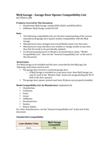
RECOMMENDED TOOLSHere are recommended tools and materials which are not supplied, but are necessary to install yourLaCantina Doors.12” x #212”#2Phillips ScrewdriverPhillips Screwdriver12”#212”x #2Flathead ScrewdriverFlatheadScrewdriver6” Phillips#2 #26” PhillipsExtensionBit BitExtension5mm5mm 5mmAllenKeyMetricAllenAllenKeyAllen KeyWrench Set6’ Spirit Level or Laser Level6’ Spirit Level Or Laser LevelCross StringCross StringsFoam FillerFoam FillerSill PanSill PanSealantSealantNOTE: Ensure all sealantsand materials used arecompatible.1Blue Painters TapeBlue Painters TapeFlashingFlashingDrill / SDS Hammer l/SDS Hammer DrillDrill Bit Index SetDrill Bit Index SetCounter SinkCounter SinkSDS Drill BitSDS Drill BitWood& PlasticShimsWood& PlasticShim
DOOR KIT PARTS LISTQuantity of parts supplied as required per systemPARTDescriptionGlazed Doors with HardwareTop TrackBottom TrackJamb LegsPivot HingePivot PlugsMagnetic Door Stop (based on configuration)Strike Door Magnetic Stop (based on configuration)Mounting Flange Set & Head Drip CapMounting Flange Corner Set2
SCREWS PARTS LISTQuantity of parts supplied as required per systemPARTDESCRIPTION12” Frame Assembly Screw24” Top Track Install Screw33 3/4” Jamb Leg Install Screw4 a2” Bottom Track Install Screw (wood)4 b2” Bottom Track Install Screw (concrete)5Pivot / Carrier / Hinge ScrewsJamb Screw Button(Buttons not supplied for custom color or custom species systems)3
HANDLE KIT PARTS LISTPARTDESCRIPTIONKey SetINTERLOCK Internal Crest Handle SetINTERLOCK External Crest Handle SetINTERLOCK Cylinder6Back Plate Screw7Cylinder ScrewSpindle Rod4
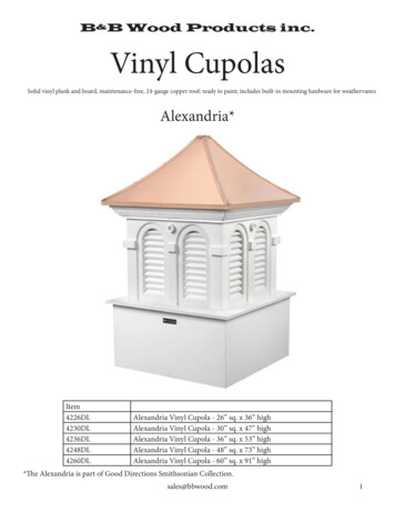
STEP 1Pre-Drill Frame Componentsa . Bottom TrackUsing 13/64” drill bit, pre-drill install holes in bottomtrack locking channel. One screw to be placed every16” on center.Center16”16”5
b. Top Track - First Drill PointUsing 13/64” drill bit, pre-drill install holesin top track. Five holes should be pre-drilledevery 3” as indicated from both ends and12” on center. Use guide line in center of toptrack for hole placement.12”3”3”3”3”3”c . Top Track - Second Drill PointUsing 13/64” drill bit, pre-drill install holesin top track’s locking channel every 24” asindicated.24”24”6
Step 1Step 2d . Jamb LegLocate guide line.8-10”NOTE: Both Jamb Legs to be pre-drilledand counter sunk8-10”even spreadAdditional screws will be required for units over 7ft.7
STEP 2Apply SealantNOTE: Prior to joining, blow out all components to remove all aluminum and vinyl debris from tracks.Failing to do this will result in pieces of aluminum sticking to roller wheels and affecting operation.Head TrackJamb LegSill TrackApply sealant to both ends of top and bottom track.Ensure hollow sections of Head and Sill are filled with sealant.Ensure full coverage of sealant on contact points including top & bottom of jamb stop.8
Joining FrameSTEP 3AABB11NOTE: Applysealant to sillcomponents.11CCDDBeing Careful to protect all surfaces lay components onsaw horses with wood interiors facing down.Align boss points with pre-drilled holes.NOTE: It is recommended to apply blue painters tape to exteriorof frame once joined. This will protect frame from scratches.9
STEP 4Apply Mounting FlangeOpening condition will vary. In the case of most new construction, opening condition is a Membrane/Drainage wall & the use of a non-integral mounting flange, supplied by LaCantina Doors, should be utilizedin conjunction with standard flashing, weather resistant barriers (House wrap), and compatible sealants.NOTE: Site conditions and materials vary. Consult with your general contractor or waterproofing expert forrecommended weatherproofing in conjunction with LaCantina System.When inserting the mounting flange into the frame ensure sealant is applied first to the kerf located 7/8”from the exterior edge of frame.NOTE: Mounting flange should not be used to locate frame in opening. It should be used to assist in weatherproofing only.Underside of thehead mounting flangeHead mountingflangewith dripedgeMountingflange1 1/2”1 1/4”1 1/2”KerfMounting flanges overlap at the cornerNOTE: Some fabrication is requiredwhere flanges meet and overlap.NOTE: White corners to be applied onceinstallation and flashing are applied.Apply sealant to any exposed gaps.10
STEP 5Installing FramePrimary head screws are mounted into the head beam at an angle, secondary head screws are mounted intothe head beam at a 90 angle.NOTE: Refer to your LaCantina Doors order form to reference swing direction, and review applicablesection detail to verify frame orientation in relation to the opening.NOTE: LaCantina Doors recommends sill pans and consultation with a water proofing consultant for anadequate drainage system.PrimaryFixing PointSecondaryFixing PointPlace shims 3” on both sides of the head. This will prevent rolling of head at corners.3”3”Outside View11
Ensure that all screws can be removed if necessary during the installation process.Do not fix off frame permanently prior to final adjustment of frame.1/8”1/8”222 232232222 – 3/16”34 – 3/16”31/8” MaxOutside View Stand frame into opening and screw frame to base,studs and header.Use cross strings and a level to ensure frame is plumb, square and level. Attach sill first, using either wood or concrete screwssupplied. Apply silicone to bottom track install holesprior to fastening also apply silicone to screw headonce fastened. Refer to page 3.4a if system is mounted into wood4b if system is mounted into concrete Attach jamb leg, using supplied screws.Ensure jamb legs are shimmed at fixing points to prevent “rolling” of frame. Attach top track to header using supplied screws .It is recommended to have a 1/8” crown in top track to allow for structural movement and possiblesagging of header. Clean top track of all metal shavings.NOTE: Do not shim head track in case of required adjustment at later date.NOTE: Jamb and Head installation screws supplied with the system are for wood framing and headeronly. Headers made from other materials such as steel should be fixed with alternate fasteners. Apply jamb buttons over screws.12
Hanging DoorsSTEP 6NOTE: If doors have exposed wood, it is recommended that top and bottom ofdoors be sealed prior to installation.Begin panel installation from pivot panel at jamb leg.a . Position panel perpendicular to frame. Locate bottom pivot hinge at bottom of panel over bottom pivotassembly and rotate onto pin. Carefully slide panel downward.5Inside Viewb.Side Viewa.b. Rotate top of panel toward frame and align top pivot hinge holeswith pre-drilled holes in edge of panel. Insert screws.13
JambPivotBolt1/4”c.Outside Viewc . Adjust pivot door. Gap between door and jamb leg should be approximately 1/4” - 3/16”.NOTE: Refer to page 25 for adjustment instructions.14
STEP 7Hanging Hinge Door5Side View55Attach Hinge Door to Pivot Door using pre-drilled holes.Use shims to support door while hanging.15
Hanging Carrier DoorSTEP 855Side View5Attach Carrier Door to Hinge Door using pre-drilled holes.Use shims to support door while hanging.NOTE: For configurations consisting of more doors, repeat steps as previously indicated foradditional doors.16
STEP 9Installing HandleAssemble and attach handle to Active Panel.676InteriorExteriorDoor Handle and Multipoint Lock Operation.To lock door, close andlift handle up to activatemulti-point lock prior toengaging deadbolt.To unlock and open,disengage deadbolt withkey or thumbturn thenopen by pushing handlefully down.Use key or thumbturn toengage deadbolt.Interior17Exterior
STEP 10Attach Magnetic Active Door StopNOTE: For 3 & 5 panel systems onlyOutside ViewAttach magnetic stops on active door.Attach magnetic stop to adjacent door as indicated.Pre-drill with 9/64” drill bit and use supplied screws.18
For swinging door with daily or dummyhandle, the active door stop shouldbe used. Refer to configuration charton pages 33-36 for systems that usemagnetic active door stops.a . Assemble the doorcatch in the order shown.Ensure the springs remain in place.b. The recommended locationof the door catch is as shown.3”From bottomto bottom edge(3 1/4” from screwto bottom of door)1/2”From edge191/2”Screw centerto edge
c . Attach to the door.1) Pre-drill the screw hole, fix the set onto the door panel as shown.2) Add the cover, ensuring the clip is through the slots on each side.3) Repeat for each door catch.d . Removing the stop.Push the clips in on both sides with a screwdriver to remove the cover from the base.Unscrew the screws to remove the door catchfrom the door panel.Cut and use template forplacement of drill holes2 1/4”13/16”20
STEP 11Attach Strike Door MagnetNOTE: For 4 panel systems onlyOutside ViewAttach magnetic stops on non active swinging door.Attach magnetic stop to adjacent door as indicated.Pre-drill with 1/8” drill bit and use supplied screwsNOTE: The vertical door stop should only be used when a handle is notpresent.21
For swinging door without a handle or dummyhandle, the strike door magnet should beused. Refer to configuration chart on pages33-36 for systems that use strike door stops.a . Assemble the doorcatch as shown.1”Screw centerto edgeb. The recommended location of3”Bottom ofDoor Catch tobottom of door3 3/8”Screw centerto edgethe door catch is as shown.c . Attach to the door.1) After pre-drilling the screw hole, fixthe set onto the door panel as shown.2) Repeat for each door catch.Cut and use template forplacement of drill holes1 3/8”5/16”22
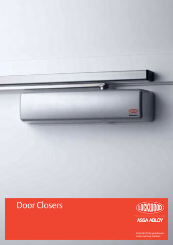
Final AdjustmentsSTEP 12Adjustment features all for vertical and horizontal adjustment.Adjust all hangers and toppivot until panels are parallelwith 7mm gap between thetrack.7[0.28]TRACKPANEL1/4"DEPRESSBUTTONOutside View3/8” Standard Sill5/16” All other sillesVertical Adjustment.1. Vertical adjustment is achieved by using a 5mm Allen wrench. To make the vertical adjustmentyour doors should be fully closed. You will need to be on the outside of your doors to make theseadjustments. A ladder may be required.2. There are two points where you can adjust your system vertically. One is at the top pivot assemblylocated at the end of your door system. The other is on the top carrier located on the doors toward themiddle of your system.3. Depending on the configuration and number of doors in your system there may be more than one pivotand carrier. The top pivot assembly and the top carrier assembly hinge pins have a location at thebottom to accommodate your allen wrench.4. By turning the pin clockwise or counterclockwise you can move your doors up and down respectively.Adjustment at these points should be done simultaneously so that an even reveal at the top and bottomof your door panels is achieved.5. Ideally you want approximately a 1/4” gap between the top of your doors and the top track and a 3/8”gap between the bottom of your doors and the bottom track for weather resistant sills and 5/16” for allother sill types.Adjusted height, depress button and wind bolt. Button locks offautomatically on flatsNOTE: If locking pin is not engaged your doors will self adjust, leading toadjustment problems and possible damage to your door system.DEPRESSBUTTON23
JAMBPIVOTBOLT3/8"Outside ViewHorizontal Adjustment.1. Horizontal adjustment is achieved by using a 5mm Allen wrench. A ladder may be required.2. There are three different points where you can adjust your system horizontally. One is at the top pivotassembly located inside the top track above the end pivot door.3. The bottom pivot assembly located inside the bottom track directly below the end pivot door. Byturning these screws clockwise and counterclockwise you can move your doors in and out respectively.To have an even reveal between your end pivot doors and your jamb legs the two points of horizontaladjustment should be adjusted together. If you only adjust the top OR the bottom it will cause yourdoors to “tilt” and may cause issues with the active door on the opposite end.4. Adjust the jamb pivot bolt last by turning clockwise or counter clockwise until the threaded sectionaligns with the hinge bolt.5. Depending on system type and configuration, pivot doors can be adjusted to 1/4” and active doors canbe adjusted approximately 3/8” from the jamb leg.6. Once the system is adjusted, use a 2mm Allen to ensure all anit-shake set/grub screws are locked/secured in place. Refer to page 28.IMPORTANT NOTE:Once doors have been installed and adjusted, close the doors and do not use the openingas a thoroughfare for transferring other building materials. Threshold should be covereduntil completion of project.24
Handing end set hingeLeftRightHanding pivot set hingeLock off anti-shake set/grub screw.ANTI-SHAKESET-GRUB SCREWANTI-SHAKESET-GRUB SCREWRight* For right,flip hingeLeftSystem securityGuide CREWHanger securityNOTE:Type H hinge shown but security set/grub screw applicable in hinge types T and M as well25
3/8” Gap between panels1 32” Gap between panel& seal* Located from theinside of the doorInterior ViewMeeting Doors Adjustment.The meeting door adjustment is for configurations that have an active door closing on another door.Refer to configuration chart on pages 33-36 for systems that have this configuration. The gap betweenthe active door and strike door is 3/8”, when aligned properly a 1/32” gap should be left between theweatherseal and the active door.IMPORTANT NOTE:The lock should operate freely with no pressure when the handle is lifted upward to engage thelocking mechanism. Failure to adjust the doors for proper operation will put stress on the lock andcause damage not covered under warranty.26
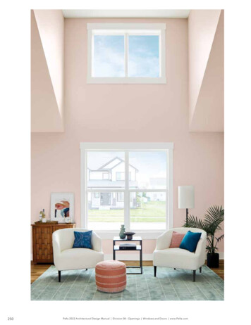
STEP 13Opening and Closing DoorsActive DoorCarrier ulti-PointLocking SystemTwin Bolt LockPullHandlePivot Door
Opening Doorsa . Open active door.Unlock and fully open active door 180 .NOTE: Not all systems have an activedoor, if no active door is presentcontinue to step b.b. Unlock lever handle.Unlock the lever handle and push on panels.c . Open door.Continue to slide panels until the doorreaches the desired 90 against the jamb.If system has single swing active door, ensure door is secured whenin the open position. Failure to do so may result in damage if windof other force pushes door back against jamb.NOTE: Refer to step 11 to apply kick down stop28
Closing DoorsNOTE: Do not pull or dragdoors shut from end panel.This will damage the doors.a . Pull panel.Glide panel stack across applying even pressureuntil panels are at a 45 angle.NOTE: This may need to be repeated basedon the number of panels.b. Use pull handle.Starting with the end panels closest to thejamb, use the pull handle to close doors.NOTE: Do not pull on lever handle as this maycause damage to the locking mechanism.NOTE: Keep fingers clear of gap between panels,failure to do so could cause serious injury.c . Engaging lock.While pulling on the pull handle,lock lever handle into the down position.NOTE: If lever handle is not engaging,then there is not sufficient force beingapplied to the pull handle.d . Locking active door.Once all passive doors are locked in placepull the active door closed and engage lock.29
Configuration ChartFind your configuration in the left column.The right column will tell you in which order to hang your doors.All Systems are viewed from the outside and panels numbered from left to right.CONFIGURATIONORDER TO HANG DOORS0Left 2RightDOOR 2 (Pivot Door), DOOR 1 (Hinge Door)2L 0RDOOR 1 (Pivot Door), DOOR 2 (Hinge Door)1L 1RDOOR 1 (Pivot Door), DOOR 2 (Pivot Door)(Includes 2 kick stops)0L 3RDOOR 3 (Pivot Door), DOOR 2 (Hinge Door), DOOR 1 (Carrier Door)(Includes 1 magnetic door stop)3L 0RDOOR 1 (Pivot Door), DOOR 2 (Hinge Door), DOOR 3 (Carrier Door)(Includes 1 magnetic door stop)1L 2RDOOR 3 (Pivot Door), DOOR 2 (Hinge Door), DOOR 1 (Pivot Door)(Includes 1 kick stop)2L 1RDOOR 1 (Pivot Door), DOOR 2 (Hinge Door), DOOR 3 (Pivot Door)(Includes 1 kick stop)0L 4RDOOR 4 (Pivot Door), DOOR 3 (Hinge Door), DOOR 2 (Carrier Door), DOOR 1(Hinge Door)4L 0RDOOR 1 (Pivot Door), DOOR 2 (Hinge Door), DOOR 3 (Carrier Door), DOOR 4(Hinge Door)2L 2RDOOR 1 (Pivot Door), DOOR 2 (Hinge Door), DOOR 4 (Pivot Door), DOOR 3(Hinge Door)1L 3RDOOR 4 (Pivot Door), DOOR 3 (Hinge Door), DOOR 2 (Carrier Door), DOOR 1(Pivot Door)(Includes 1 vertical stop and 1 kick stop)3L 1RDOOR 1 (Pivot Door), DOOR 2 (Hinge Door), DOOR 3 (Carrier Door), DOOR 4(Pivot Door)(Includes 1 vertical stop and 1 kick stop)0L 5RDOOR 5 (Pivot Door), DOOR 4 (Hinge Door), DOOR 3 (Carrier Door), DOOR 2(Hinge Door), DOOR 1 (Carrier Door)(Includes 1 magnetic door stop)5L 0RDOOR 1 (Pivot Door), DOOR 2 (Hinge Door), DOOR 3 (Carrier Door), DOOR 4(Hinge Door), DOOR 5 (Carrier Door)(Includes 1 magnetic door stop)1L 4RDOOR 5 (Pivot Door), DOOR 4 (Hinge Door), DOOR 3 (Carrier Door), DOOR 2(Hinge Door), DOOR 1 (Pivot Door)(Includes 1 kick stop)4L 1RDOOR 1 (Pivot Door), DOOR 2 (Hinge Door), DOOR 3 (Carrier Door), DOOR 4(Hinge Door), DOOR 5 (Pivot Door)(Includes 1 kick stop)2L 3RDOOR 5 (Pivot Door), DOOR 4 (Hinge Door), DOOR 3 (Carrier Door), DOOR 1(Pivot Door), DOOR 2 (Hinge Door)(Includes 1 magnetic door stop)3L 2RDOOR 1 (Pivot Door), DOOR 2 (Hinge Door), DOOR 3 (Carrier Door), DOOR 5(Pivot Door), DOOR 4 (Hinge Door)(Includes 1 magnetic door stop)0L 6RDOOR 6 (Pivot Door), DOOR 5 (Hinge Door), DOOR 4 (Carrier Door), DOOR 3(Hinge Door), DOOR 2 (Carrier Door), DOOR 1 (Hinge Door)30
CONFIGURATIONORDER TO HANG DOORS6L 0RDOOR 1 (Pivot Door), DOOR 2 (Hinge Door), DOOR 3 (Carrier Door), DOOR 4(Hinge Door), DOOR 5 (Carrier Door), DOOR 6 (Hinge Door)3L 3RDOOR 1 (Pivot Door), DOOR 2 (Hinge Door), DOOR 3 (Carrier Door), DOOR 6(Pivot Door), DOOR 5 (Hinge Door), DOOR 4 (Carrier Door)(Includes 1 magnetic door stop and 1 vertical stop)1L 5RDOOR 6 (Pivot Door), DOOR 5 (Hinge Door), DOOR 4 (Carrier Door), DOOR 3(Hinge Door), DOOR 2 (Carrier Door), DOOR 1 (Pivot Door)(Includes 1 vertical stop and 1 kick stop)5L 1RDOOR 1 (Pivot Door), DOOR 2 (Hinge Door), DOOR 3 (Carrier Door), DOOR 4(Hinge Door), DOOR 5 (Carrier Door), DOOR 6 (Pivot Door)(Includes 1 vertical stop and 1 kick stop)2L 4RDOOR 1 (Pivot Door), DOOR 2 (Hinge Door), DOOR 6 (Pivot Door), DOOR 5(Hinge Door), DOOR 4 (Carrier Door), DOOR 3 (Hinge Door)4L 2RDOOR 6 (Pivot Door), DOOR 5 (Hinge Door), DOOR 4 (Carrier Door), DOOR 3(Hinge Door), DOOR 1 (Pivot Door), DOOR 2 (Hinge Door)31
Limited WarrantyThis express limited warranty is effective for product manufactured by LaCantina Doors, Inc. (“LaCantina”) afterMarch 1, 2011, extends to all original end users and is not transferable.WARRANTY COVERAGESubject to the conditions, exclusions and limitations of this limited warranty, we warrant our glass andcomponents below will be free from defects in materials and workmanship which would render the productunserviceable or unfit for ordinary recommended use from the date of shipment for the following time periods:Glass – We warrant insulated glass against failure of the air seal and that each unit will be free from materialobstruction of vision as a result of fogging or film formation on the internal surfaces. We warrant laminated glassagainst delamination resulting in materially obstructed vision through the laminated glass. All glass is warrantedfor a period of twenty (20) years.Component Finishes – LaCantina standard aluminum paint finish is warranted for a period of ten (10) yearsagainst defects resulting in cracking, peeling and other loss of adhesion. Optional and Custom color paint finishesare warranted for a period of ten (10) years unless in coastal environments (within three (3) miles of a sea coastor salt water, which will be warranted for a period of one (1) year). Anodized finishes are warranted for a periodof three (3) years unless in coastal environment (within three (3) miles of a sea coast or salt water which willbe warranted for a period of one (1) year). LaCantina standard vinyl is warranted for a period of ten (10) yearsagainst manufacturing defects which results in rotting, cracking, warping, pitting, corroding, peeling, blistering,or non-uniform color.Hardware and Components – Folding system and swing door carriers, pivots, surface mounted locks and hingeswill be warranted for a period of ten (10) years. Multipoint and locking mechanisms will be warranted for a periodof five (5) years. Sliding system hardware components including multipoint lock mechanisms and rolling hardwarewill be warranted for a period of ten (10) years.All hardware products should be cleaned and maintained as recommended below and as frequently as necessary.Hardware in coastal and salt water environments should be cleaned and maintained every three (3) months as aminimum and more frequently to prevent buildup of salt water or corrosive residue. In event of a warranty claimuser must be able to present maintenance schedule as recommended below.Weather Seals - All seals are warranted for a period of ten (10) years. Systems should be adjusted as per ourrecommendation and according to variances in site conditions so as not to put undue stress and/or pressure onseals during operation.Screens – When installed to the interior of a residence or place of business, both pleated and non-pleated screensare warranted for a period of five (5) years. Exterior application of screen is not recommended. Screens easilydislodge from the track if fallen on and are not designed to prevent falls.Export Limitation - The maximum warranty period for any product used outside of the United States is two (2)years on glass and components and ten (10) years on folding system hardware.WARRANTY CONDITIONS, EXCLUSIONS AND LIMITATIONSThis warranty is limited to defects in materials and workmanship and expressly excludes damage or defectscaused by or arising from: Minor glass imperfections which do not impair structural integrity or obscure normal vision, including slightbubbles, lines, surface imperfections or discolorations; any imperfections in the glass not detected fromwithin ten feet whilst looking through the glass as per the guidelines established by federal st
table of contents recommended tools and materials 1 parts list 2 step 1 - pre-drill frame components 5 step 2 - apply sealant 8 step 3 - joining frame 9 step 4 - apply mounting flange 10 step 5 - installing frame 11 step 6 - hanging doors 13 step 7 - hanging hinge door 15 step 8 - hanging carrier door 16 step 9 - installing handle 17 step 10 - attach magnetic active 18 step 11 - attach strike .