Transcription
DTX SeriesCableAnalyzer Users ManualPN 2142201April 2004, Rev. 7 8/10 2004, 2006-2010 Fluke Corporation. All rights reserved. Printed in USA.All product names are trademarks of their respective companies.
LIMITED WARRANTY AND LIMITATION OF LIABILITYEach Fluke Networks product is warranted to be free from defects in material and workmanship under normal use and service. Thewarranty period for the mainframe is one year and begins on the date of purchase. Parts, accessories, product repairs and services arewarranted for 90 days, unless otherwise stated. Ni-Cad, Ni-MH and Li-Ion batteries, cables or other peripherals are all considered partsor accessories. The warranty extends only to the original buyer or end user customer of a Fluke Networks authorized reseller, and doesnot apply to any product which, in Fluke Networks’ opinion, has been misused, abused, altered, neglected, contaminated, or damagedby accident or abnormal conditions of operation or handling. Fluke Networks warrants that software will operate substantially inaccordance with its functional specifications for 90 days and that it has been properly recorded on non-defective media. Fluke Networksdoes not warrant that software will be error free or operate without interruption.Fluke Networks authorized resellers shall extend this warranty on new and unused products to end-user customers only but have noauthority to extend a greater or different warranty on behalf of Fluke Networks. Warranty support is available only if product ispurchased through a Fluke Networks authorized sales outlet or Buyer has paid the applicable international price. Fluke Networksreserves the right to invoice Buyer for importation costs of repair/replacement parts when product purchased in one country issubmitted for repair in another country.Fluke Networks warranty obligation is limited, at Fluke Networks option, to refund of the purchase price, free of charge repair, orreplacement of a defective product which is returned to a Fluke Networks authorized service center within the warranty period.To obtain warranty service, contact your nearest Fluke Networks authorized service center to obtain return authorization information,then send the product to that service center, with a description of the difficulty, postage and insurance prepaid (FOB destination). FlukeNetworks assumes no risk for damage in transit. Following warranty repair, the product will be returned to Buyer, transportationprepaid (FOB destination). If Fluke Networks determines that failure was caused by neglect, misuse, contamination, alteration, accidentor abnormal condition of operation or handling, or normal wear and tear of mechanical components, Fluke Networks will provide anestimate of repair costs and obtain authorization before commencing the work. Following repair, the product will be returned to theBuyer transportation prepaid and the Buyer will be billed for the repair and return transportation charges (FOB Shipping point).THIS WARRANTY IS BUYER’S SOLE AND EXCLUSIVE REMEDY AND IS IN LIEU OF ALL OTHER WARRANTIES, EXPRESS OR IMPLIED,INCLUDING BUT NOT LIMITED TO ANY IMPLIED WARRANTY OR MERCHANTABILITY OR FITNESS FOR A PARTICULAR PURPOSE. FLUKENETWORKS SHALL NOT BE LIABLE FOR ANY SPECIAL, INDIRECT, INCIDENTAL OR CONSEQUENTIAL DAMAGES OR LOSSES, INCLUDINGLOSS OF DATA, ARISING FROM ANY CAUSE OR THEORY.Since some countries or states do not allow limitation of the term of an implied warranty, or exclusion or limitation of incidental orconsequential damages, the limitations and exclusions of this warranty may not apply to every buyer. If any provision of this Warrantyis held invalid or unenforceable by a court or other decision-maker of competent jurisdiction, such holding will not affect the validity orenforceability of any other provision.4/04Fluke NetworksPO Box 777Everett, WA 98206-0777USA
ContentsTitleOverview of Features .Registration .Contacting Fluke Networks .Accessing the Technical Reference Handbook .Additional Resources for Cable Testing Information .Unpacking .DTX-1800 .DTX-1200 .DTX-LT .Safety Information .Getting Acquainted .Physical Features .Powering the Tester .Localizing the Tester .About Link Interface Adapters .Preparing to Save Tests .Certifying Twisted Pair Cabling .iPage1223344455881414161920
DTX Series CableAnalyzerUsers ManualSetting the Reference for Twisted Pair Cabling .Twisted Pair Test Settings .Autotest on Twisted Pair Cabling .Autotest Summary Results for Twisted Pair Cabling .PASS*/FAIL* Results .Automatic Diagnostics .Certifying Coaxial Cabling .Setting the Reference for Coaxial Cabling .Coaxial Test Settings .Autotest on Coaxial Cabling .Autotest Results for Coaxial Cabling .Cable ID Options .Verifying Network Service .Installing and Removing the Network Module and Optional SFP Module .Network Connectivity Test Settings .Testing for Network Connectivity .About Testing for PoE (Power Over Ethernet) .Pinging Network Devices .Monitoring Network Traffic .Blinking a Port Light .Identifying Links (twisted pair only) .Memory Functions .Formatting the Memory Card (DTX-1800 and DTX-1200) or Internal Memory .Setting the Storage Location (DTX-1800 and DTX-1200) .Viewing Results .Moving and Deleting Results .DTX-1800, DTX-1200 .All Models 455555556
ContentsUploading Results to a PC .Options and Accessories .About LinkWare and LinkWare Stats Software .Maintenance .Cleaning .Factory Calibration .Updating the Tester’s Software .Updating with a PC .Updating with Another Tester .Updating with a Memory Card (DTX-1800, DTX-1200) .Updating the Limits or Cable Types Database .Retraining the Battery Gauge .Certification and Compliance .CSA Standards .Safety .Regulatory Information .Index .iii5657575858585959616262636464646465
DTX Series CableAnalyzerUsers Manualiv
List of 3.14.15.16.17.Tester Front Panel Features .Tester Side and Top Panel Features .Smart Remote Features.Removing the Battery Pack.Smart Remote Battery Status Shown After Power-Up.Attaching and Removing Adapters.Handling Guidelines for Permanent Link Adapters .Changing the Personality Module on DTX-PLA001 Adapters .Twisted Pair Reference Connections .Outlet Configurations .Equipment for Certifying Twisted Pair Cabling.Permanent Link Test Connections .Channel Test Connections.Autotest Summary for Twisted Pair Cabling .PASS* and FAIL* Results .Examples of Automatic Diagnostic Screens .Coaxial Reference Connections .810121515161718212325272829303133v
DTX Series CableAnalyzerUsers ment for Certifying Coaxial Cabling .Coaxial Network Cabling Test Connections .Coaxial Video Cabling Test Connections.Autotest Results for Coaxial Cabling.Network Module Features .Installing and Removing the Network and SFP Modules.Network Test Connections .Network Connectivity Results Screen (DHCP example for twisted pair) .Ping Results Screen .Traffic Monitor Screen .Identifying Links with Optional LinkRunner Cable ID Locators.Updating the Software with a PC .Updating the Software with an Updated Tester.vi36383940424345464951536061
DTX Series CableAnalyzerOverview of Features Automatic diagnostics report distance to and likelycauses of common faults.The DTX Series CableAnalyzers are rugged, hand-heldinstruments used to certify, troubleshoot, and documentcopper and fiber cabling installations. The testers featurethe following: Toner feature helps you locate jacks and automaticallystarts an Autotest upon tone detection. Optional fiber modules let you certify multimode andsinglemode fiber optic cabling. Optional DTX-OTDR modules let you locate andcharacterize reflective and loss events in optical fibers. Optional DTX-NSM module lets you verify networkservice. Optional DTX 10 Gig kit lets you test and certify Cat 6and Augmented Cat 6 (Cat 6A) cabling for10 Gigabit Ethernet applications. Stores up to 250 Cat 6 Autotest results, includinggraphical data, in internal memory. The DTX-1800 certifies twisted pair and coaxialcabling to Class F limits (600 MHz) in less than25 seconds and Category 6 cabling in less than10 seconds. The DTX-1200 certifies Category 6 cablingin less than 10 seconds. Meet Level III and Level IVaccuracy requirements. The DTX-LT certifies Category 6 cabling in less than28 seconds. All models meet Level III and Level IVaccuracy requirements. Color display clearly indicates PASS/FAIL results.1
DTX Series CableAnalyzerUsers Manual The DTX-1800 and DTX-1200 store up to 4,000Autotest results, including graphical data, on a128 MB removable memory card. (See page 54 forstorage recommendations.) Runs for at least 12 hours on the rechargeable lithiumion battery pack. Smart remote with optional fiber module can be usedwith Fluke Networks OF-500 OptiFiber CertifyingOTDR for loss/length certification. LinkWare software lets you upload test results to a PCto create professional-quality test reports. TheLinkWare Stats option generates browsable, graphicalreports of cable test statistics.RegistrationRegistering your product with Fluke Networks gives youaccess to valuable information on product updates,troubleshooting tips, and other support services.To register, fill out the online registration form on theFluke Networks website at www.flukenetworks.com/registration.2Contacting Fluke NetworksNoteIf you contact Fluke Networks about your tester,have the tester’s software and hardware versionnumbers available if s.com 1-425-446-4519 Australia: 61 (2) 8850-3333 or 61 (3) 9329 0244 Beijing: 86 (10) 6512-3435 Brazil: 11 3759 7600 Canada: 1-800-363-5853 Europe: 31-(0) 40 2675 600 Hong Kong: 852 2721-3228
Accessing the Technical Reference Handbook Japan: 03-6714-3117 Korea: 82 2 539-6311 Singapore: 65-6799-5566 Taiwan: (886) 2-227-83199 USA: 1-800-283-5853Visit our website for a complete list of phone numbers.Additional Resources for Cable TestingInformationThe Fluke Networks Knowledge Base answers commonquestions about Fluke Networks products and providesarticles on cable testing techniques and technology.To access the Knowledge Base, log on towww.flukenetworks.com, then click Customer Support Knowledge Base.Accessing the Technical ReferenceHandbookThe DTX CableAnalyzer Technical Reference Handbookprovides additional information on the tester. Thehandbook is available on the DTX CableAnalyzer ProductCD included with your tester and on the DTXCableAnalyzer product page on the Fluke Networkswebsite.3
DTX Series CableAnalyzerUsers ManualUnpackingThe DTX Series CableAnalyzers come with the accessorieslisted below. If something is damaged or missing, contactthe place of purchase immediately.DTX-1200 DTX-1200 CableAnalyzer with lithium-ion batterypack DTX-1200 SmartRemote with lithium-ion battery pack Two Cat 6A/Class EA permanent link adaptersDTX-1800 Two Cat 6A/Class EA channel adaptersDTX-1800 CableAnalyzer with lithium-ion batterypack Two headsetsDTX-1800 SmartRemote with lithium-ion battery pack Carrying case Two carrying straps USB cable for PC communications Two ac adapters DTX Series CableAnalyzer Users ManualTwo carrying straps DTX Series CableAnalyzer Product CDMemory card LinkWare Software CD 4Two Cat 6A/Class EA permanent link adaptersTwo Cat 6A/Class EA channel adaptersTwo headsetsCarrying caseUSB cable for PC communicationsDTX RS-232 serial cable for PC communicationsTwo ac adaptersDTX Series CableAnalyzer Users ManualDTX Series CableAnalyzer Product CDLinkWare Software CD
Safety InformationDTX-LT DTX-LT CableAnalyzer with lithium-ion battery pack DTX-LT SmartRemote with lithium-ion battery pack Two Cat 6A/Class EA permanent link adapters One Cat 6A/Class EA channel adapter Carrying case Two carrying straps USB cable for PC communications Two ac adapters DTX Series CableAnalyzer Users Manual DTX Series CableAnalyzer Product CD LinkWare Software CDSafety InformationTable 1 shows the international electrical symbols used onthe tester or in this manual.Table 1. International Electrical SymbolsXWarning: Risk of fire, electric shock, orpersonal injury.WWarning or Caution: Risk of damage ordestruction to equipment or software. Seeexplanations in the manuals.jDo not connect this equipment to publiccommunications networks, such as telephonesystems.* Warning: Class 1 laser (OUTPUT port). Risk ofeye damage from hazardous radiation.Class 2 laser (VFL port). Do not stare intobeam.Do not put products containing circuit boardsinto the garbage. Dispose of circuit boards inaccordance with local regulations.5
DTX Series CableAnalyzerUsers ManualWWarningX Always turn on the tester before connecting it toa cable. Turning the tester on activates the tool’sinput protection circuitry. Do not use the tester if it operates abnormally.Protection may be impaired.To avoid possible fire, electric shock, or personalinjury: Do not open the case; no user-serviceable partsare inside. Do not modify the tester. Use only ac adapters approved by Fluke Networksfor use with the DTX tester to charge the batteryor power the tester. When servicing the tester, use only specifiedreplacement parts. Never connect the tester to an active network.Doing so may disrupt network operation. Do not use the tester if it is damaged. Inspect thetester before use. If this equipment is used in a manner not specifiedby the manufacturer, the protection provided bythe equipment may be impaired.Never attempt to insert any connector otherthan an 8-pin modular (RJ45) connector into anadapter’s jack. Inserting other connectors, suchas RJ11 (telephone) connectors, canpermanently damage the jack. Never connect the tester to any telephony inputs,systems, or equipment, including ISDN. Doing sois a misapplication of this product, which canresult in damage to the tester and create apotential shock hazard to the user.6WCautionTo avoid disrupting network operation, toavoid damaging the tester or cables under test,to avoid data loss, and to ensure maximumaccuracy of test results:
Safety Information Never operate portable transmitting devices,such as walkie-talkies and cell phones, during acable test. Doing so might cause erroneous testresults. To ensure maximum accuracy of copper cabletest results, perform the reference procedureevery 30 days as described under “Setting theReference”. The permanent link interface adapters may notperform properly or may be damaged if theyare handled improperly. See pages 16 and 17for important handling information. Leave the module bay covers in place whenmodules are not installed. See page 10. Turn off the tester before attaching or removingmodules. Never remove the memory card while thememory card’s LED is on. Doing so can corrupt thedata on the card. Memory cards may be lost, damaged, oraccidentally formatted, resulting in data loss.Therefore, Fluke Networks recommends saving nomore than one day’s worth of test results on amemory card.WWarning: Class 1 and Class 2 LaserProducts*To avoid possible eye damage caused byhazardous radiation, when using the fibermodules follow the safety guidelines given inthe DTX-MFM2/GFM2/SFM2 Fiber Module UsersManual or the DTX Series CableAnalyzerTechnical Reference Handbook.7
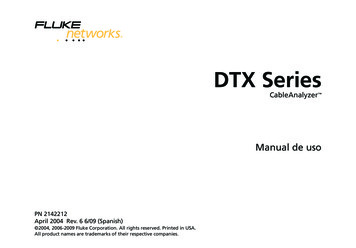
DTX Series CableAnalyzerUsers ManualGetting AcquaintedPhysical FeaturesThe following sections introduce the tester’s basic features.Figures 1 and 2 describe the tester’s features. Figure 3describes the smart remote’s f.epsFigure 1. Tester Front Panel Features8
Getting AcquaintedA LCD display with backlight and adjustable brightness.B P: Starts the currently selected test. Activates the tonegenerator for twisted pair cabling if no smart remote isdetected. The test starts when both testers areconnected.C N: Saves Autotest results in memory.D Rotary switch selects the tester’s modes.G G: Press to switch the backlight between bright anddim settings. Hold for 1 second to adjust the displaycontrast.H B C A D: Arrow keys for navigatingthrough screens and incrementing or decrementingalphanumeric values.I H: Enter key selects the highlighted item from amenu.E M: On/off key.J I: Exits the current screen without saving changes.F O: Press to use the headset to talk to the person at theK J K L: The softkeys provide functionsother end of the link.related to the current screen. The functions are shownon the screen above the keys.Figure 1. Tester Front Panel Features (cont.)9
DTX Series CableAnalyzerUsers Manualamd33f.epsFigure 2. Tester Side and Top Panel Features10
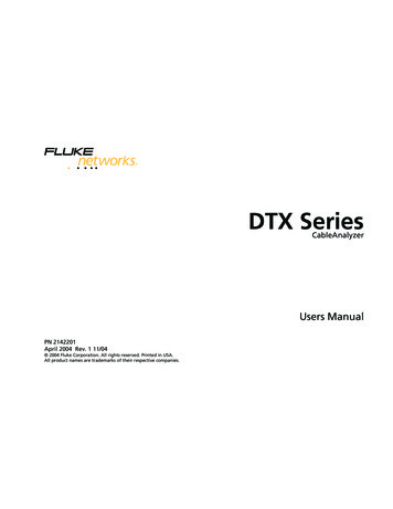
Getting AcquaintedA Connector for twisted pair interface adapters.F Headset jack for talk mode.B Cover for the module bay. Slide off the cover to installG Connector for the ac adapter. The LED turns on whenoptional modules, such as the fiber module.the tester is connected to ac power.C Bail. Red: Battery is charging.D DTX-1800 and DTX-1200: Slot and activity LED for the Green: Battery is charged.removable memory card. To eject the card, push in thenrelease the card.E USB () and RS-232C (: DTX-1800,DTX-1200) ports for uploading test reports to a PC andupdating the tester’s software. The RS-232C port uses acustom DTX cable available from Fluke Networks. Flashing red: Charge timeout. The battery failed toreach full charge within 6 hours. See “Powering theTester” on page 14.Figure 2. Tester Side and Top Panel Features (cont.)11
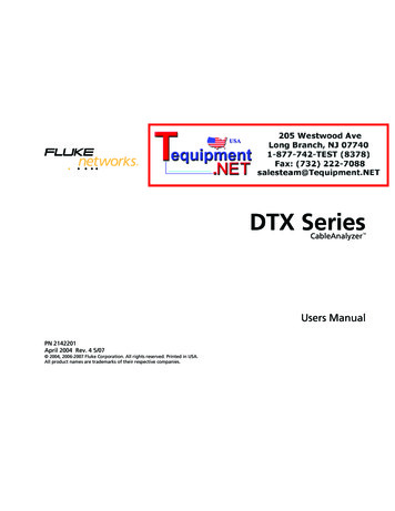
DTX Series CableAnalyzerUsers Manualamd30f.epsFigure 3. Smart Remote Features12
Getting AcquaintedWCautionG Low battery LED lights when the battery is low.All the LEDs flash if the smart remote detectsexcessive voltage on the cable. Unplug the cableimmediately if this occurs.NoteThe LEDs also act as a battery gauge. See Figure15 on page 15.H P: Starts the test currently selected on the main unit.Activates the tone generator for twisted pair cabling ifno main tester is detected. The test starts when bothtesters are connected.I O: Press to use the headset to talk to the person atthe other end of the link. Press again to adjust thevolume. Press and hold to exit talk mode.A Connector for twisted pair interface adapters.J M: On/off key.B Pass LED lights when a test passes.K USB port for updating the tester’s software with a PC.C Test LED lights during cable tests.L Headset jack for talk mode.D Fail LED lights when a test fails.M Connector for the ac adapter, as described in Figure 2.E Talk LED lights when the smart remote is in talk mode.N Cover for the module bay. Slide off the cover to installPress Oto adjust the volume.optional modules, such as the fiber module.F Tone LED lights and the tone generator turns on whenyou press P, but the main tester is not connected.Figure 3. Smart Remote Features (cont.)13
DTX Series CableAnalyzerUsers Manual Powering the Tester You may charge the battery when it is attached ordetached from the tester. Figure 4 shows how toremove the battery. The battery charges fully in about 4 hours with thetester off. A fully-charged battery lasts for at least 12hours of typical use.NoteThe battery will not charge at temperaturesoutside of 0 C to 45 C (32 F to 113 F). Thebattery charges at a reduced rate between 40 Cand 45 C (104 F and 113 F). 14If the battery does not reach full charge within 6hours, the battery LED flashes red. Verify that thebattery was within the temperature range givenabove during charging and that the correct ac adapterwas used. Disconnect then reconnect ac power and trycharging the battery again. If the battery does notcharge the second time, retrain the battery gauge.See page 63.Localizing the TesterLocal settings include Language, Date, Time, NumericFormat, Length Units, and Power Line Frequency.1Turn the rotary switch to SETUP.The battery status icon () near the upper-rightcorner of main screens shows the battery’s chargelevel. The smart remote’s LEDs show the smartremote’s battery status at the end of the power-upcycle, as shown in Figure 5.2Use D to highlight Instrument Settings at thebottom of the list; then press H.3Use Cand D to find and highlight Language onthe bottom of tab 2; then press H.For additional battery information, connect the maintester and smart remote through link adapters, turnthe rotary switch to SPECIAL FUNCTIONS; then selectBattery Status. See page 63 for information onretraining the battery gauge.4Use D to highlight the desired language; thenpress H.5Use the arrow keys and H to find and changeother local settings on tabs 2, 3, and 4 underInstrument Settings.
Getting AcquaintedPASSTEST84 % - 100 %67 % - 83 %51 % - 66 %34 % - 50 %18 % - 33 %0 % - 17 %FAILPASSTALKTONETESTLOW BATTERYFAILTALKTESTTALKTONELOW BAamd32f.epsFigure 4. Removing the Battery Packamd31f.epsFigure 5. Smart Remote Battery StatusShown After Power-Up15
DTX Series CableAnalyzerUsers ManualAbout Link Interface AdaptersLink interface adapters provide the correct jacks andinterface circuitry for testing different types of twisted pairLAN cabling. The channel and permanent link interfaceadapters provided are suitable for testing cabling up toCat 6. Optional coaxial adapters let you test coaxialcabling.Figure 6 shows how to attach and remove RSAVESAVESINGLETESTMONITORTo avoid damaging the permanent link adapterand to ensure maximum accuracy of testresults, never pinch, kink, or crush the adapter’scable. Follow the handling guidelines given inFigure sFigure 6. Attaching and Removing Adapters
Getting Acquaintedamd36f.epsFigure 7. Handling Guidelines for Permanent Link Adapters17
DTX Series CableAnalyzerUsers ManualThe DTX-PLA001 universal permanent link adapter has aremovable personality module. These may be changed tocustomize the adapter for different jack configurations.To change the personality module, do the following (referto Figure 8):1Ground yourself by touching a grounded, conductivesurface.2Remove the link interface adapter from the tester.3Use your fingers to unscrew the screw on thepersonality module.Static NITOR4Store the module in its original, static protection bag.5Put the new module in place and tighten the screwwith your fingers.WCautionTighten the screw
DTX Series CableAnalyzer Overview of Features The DTX Series CableAnalyzers are rugged, hand-held instruments used to certify, troubleshoot, and document copper and fiber cabling installations. The testers feature the following: The DTX-1800 certifies twisted pair and coaxial cabling to Class F limits (600 MHz) in less than 25