Transcription
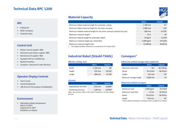
Technical Data RPC 1200Material CapacityRPC Cutting cell Roller conveyors Industrial robotMetric1.700 mm67”Minimum infeed material length for the chain conveyor3.000 mm118”600 mm23 5/8”12 m40’20 kg/m13 lb/ftMinimum outfeed material length for the chain conveyor (except last part)Maximum material length(1)Minimum material weight for automatic infeedMaximum material weight per meter/footControl Unit Motion control supplier: B&R Electronics and motors supplier: B&R Remote bus IO supplier: B&R Equipped with air conditioning Network interface Computer: Industrial PC with SSD driveOperator Display Controls Touch screen Industrial keyboard USB drive for the purpose of loading filesMaximum material weight total1.Any length possible, extensions in increments of 2 meters (6 ft). V 1.6Admissible ambient temperature:Metric 5 C/40 CImperial 41 F/ 104 FExceptions on request1.000 kg/m672 lb/ft12.000 kg26.455 lbIndustrial Robot (Stäubli TX60L)Conveyors*Effective cutting zoneInfeed and outfeed storage chains (optional)MetricImperialWidth1.220 mm48”Height475 mm18 5/8”Length400 mm15 5/8”MetricMaximum load totalSpeedHeightMaximum storage lengthAccuracyMetricImperialRepeatability ISO 92830,02 mm0,0008”Positioning accuracy1,00 mm0,0393”Note: the accuracy refers to the robot movement, not the cuttingprocess.EnvironmentImperialMinimum infeed material length for automatic cuttingImperial30 t66.139 lbs20 m/min66 ft/min915 mm36”4.000 mm13’Infeed and outfeed conveyorsMetricMaximum loadImperial1.000 kg/m672 lb/ft12 ton26.455 lbSpeed20 m/min66 ft/minHeight915 mm36”Maximum load total* These values are based on conveyors with a length of 12 meters.Technical Data Mains Connections Draft Layout
Materials Supported for ProfilingThese profile types and sizes can be cut by the RPC based on the effective robotcutting zone. Comparable sizes of other standards are also supported.Beams AmericanBeams EuropeanSection range metricMinimumMaximumAcceptable tolerancesaccording to standardSection range imperialMinimumMaximumIPE Parallel flange I sectionsIPE 100IPE 750EN 10034: 1993W Wide flange beamsIPN Taper flange I sectionsIPN 100IPN 600EN 10024: 1995S Standard beamsHE Wide flange beams (AA/A/B/M)HE 100HE 1000EN 10034: 1993HP Wide flange bearing pilesHL Extra wide flange beams*HL 920HL 1100EN 10034: 1993HD Wide flange columnsHD 260HD 400EN 10034: 1993HP Wide flange bearing pilesHP 200HP 400EN 10034: 1993* beam weight may not exceed the maximum supported material weight per meter.Acceptable tolerancesaccording to standardUPE Parallel flange channelsUPE 100UPE 400EN 10279: 2000UNP European standard channelsUNP 100UNP 400EN 10279: 2000Section range metric (in mm)MinimumMaximumAcceptable tolerancesaccording to standardNarrow flat bar100 x 15(1)150 x 40(2)EN 10058: 2003Flat bar160 x 15(2)400 x 40EN 10058: 2003(1)430 x 20EN 10067: 1997L 75L 300EN 10056-2: 1993Angle bar unequalL 100 x 50L 200 x 100EN 10056-2: 1993T-barT 100 x 50T 140EN 10055: 1996(1)Bulb100 x 6Angle bar equal1.2.ASTM A 6/A 6M - 12S4S 24ASTM A 6/A 6M - 12HP 8HP 14ASTM A 6/A 6M - 12Acceptable tolerancesaccording to standardC4C 15ASTM A 6/A 6M - 12MC 6MC 18ASTM A 6/A 6M - 12Bars American (optional)Section range imperialMinimumMaximumAngle bar equalAcceptable tolerancesaccording to standardL3L 12ASTM A 6/A 6M - 12L4x2L8x4ASTM A 6/A 6M - 12Section range imperial (inches)MinimumMaximumAcceptable tolerancesaccording to standardAngle bar unequalBars European (optional)W 44Section range imperialMinimumMaximumMC ChannelsSection range metricMinimumMaximumW4Channels American (optional)C Standard channelsChannels European (optional)Acceptable tolerancesaccording to standardHollow sections American (optional)Box section(3)3.4 x 4 x 5/1623 x 16ASTM A500A floor pit underneath the cutting cell is recommended if convenient scrap removal is required.Minimum profiles should be loaded directly onto the roller conveyors, not the chains (if present).Maximum wall thickness for profiling depends on plasma unit specifications.Hollow sections European (optional)Section range metric (in mm)MinimumMaximumBox section(3)3.100 x 100 x 8Acceptable tolerancesaccording to standard600 x 400EN 10305-5: 2010A floor pit underneath the cutting cell is recommended for easy scrap removal.V 1.6Technical Data Mains Connections Draft Layout
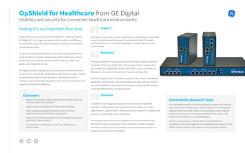
Laser and cutting technologyLaser scan surfacesDetectable surfacesTarget plates A target plate should always be used whenthe distance from the conveyor rollers tothe top of the profile when loaded is lessthan 40 mm (e.g. flat bars, bulbs). Minimum diameter hole: 2x wall thicknesswith a minimum of 8 mm; Web cuts close to the flange need an offsetand may leave a stump in cases where theflange must remain intact. The minimumstump height from the flange is 15 mm. A conventional rathole needs the sameminimum offset of 15 mm. Use HGG’sspecial ratholes to avoid minimum offsetand remove the need of rework.V 1.65 mm 234Profile length 16 meters123Profile length 18 meters41 234 8 mm 10 mm 10 mm Definitions of surfaces that can be measured in relation to distance and wall thickness:1 Target plate: a magnetic plate that is attached to the end of the beam or profile.2 Clean saw cut: a clean, straight cut that is free from rust.3 White paint: a straight flat surface treated with paint.4 Rusty: a straight but rusty flat surface.Plasma Cutting Kjellberg (Mild steel)Plasma unitDiameter hole 40 mm: no dependency.Web CuttingProfile length 12 - 14 meters1A magnetic plate attached to the end ofthe material provides an easy target for thelaser which will increase productivity.Cutting Holes Wall ThicknessMaximum cutting length(1)Minimum wall thicknessMaximum wall thicknessfor piercingMaximumbevel ocus 280i neo50 - 70 mm2 - 3”5 mm(2)3/16”40 mm1 1/2”45 HiFocus 440i neo80 - 120 mm3 - 5”5 mm3/16”2”45 1.2.3.(2)50 mm(3)(3)This column represents the cutting length ranges ‘maximum high quality cutting length’ to ‘maximum cutting length’. Values aredependent on the material to be cut, its composition and the cutting speed. It is not related to the maximum wall thickness for piercing.This data is according to Kjellberg documentation. HGG guarantees quality at 6 mm minimum wall thickness.This data is according to Kjellberg documentation. HGG quarantees quality up to 40 mm maximum wall thickness for piercing.Technical Data Mains Connections Draft Layout
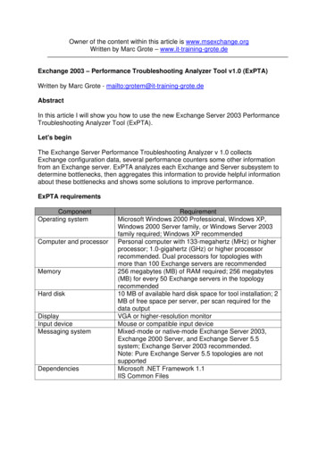
Marking and AccuracyPlasma MarkingSupported marking surfacesTop webBottom webMarkingProfile Flat barN/AYESNON/ABulb/HPN/AYESNON/AAngle (equal)YESYESNON/AAngle SYESCutting AccuracySHSYESYESYESYES All accuracy data is according to ISO 9013;bevel deviation 2 .ChannelYESYESYESYES Cut values based on clean mild steelmaterial without deviations. Sufficient training by HGG is required toobtain the mentioned accuracies. Cutting paths with sharp corners mayinfluence tolerances. Cutting accuracy is not related to the torchpositioning accuracy.Bottom flangeTOP WEBBOTTOMFLANGEMarking is supported with DSTV Teklaimport or manual data input in ProCAM.Top flangeTOP FLANGE Plasma marking is available as anintegrated feature on the torch. Markingrequires additional gas connections.ShapeBOTTOM WEBPROFILE ORIENTATION ON THE MACHINEPlasma Cutting AccuracyDouble BevellingCutting lengthTilt angle in degrees0 45 Constraints of thermal cutting process5 - 15 mm0.5 mm1.0 mmwall thickness (t)15 - 30 mm0.8 mm1.5 mm30 - 50 mm1.5 mm2.5 mm50 - 75 mm2.0 mm- Double bevel: t 15 mm Single bevel with nose: t 15 mm Double bevel with nose: t 20 mm Nose: height 5 mm (smaller sizespossible but results are inaccurate).V 1.6Note: Maximum cutting length depends on type of plasma source.Technical Data Mains Connections Draft Layout
Mains ConnectionsThese pages contains all connection specificationsand values for the machine gas and powerconsumption. The connected load will differdepending on the offered machine configuration.Machine ConsumptionPowerControl unitStäubli TX60L RobotPower Supply Power supply: 3 phase/PEMains AC voltage 10% -5%Mains frequency 1 HzRecommended fuses are based on 400 VThe given pressure, flow rates and powerconsumption of the plasma supplies aremaximum values.Gas18 kVA fuse 3 x 32 A slowAir 7 bar & 8000 Ndm3/h 4 kVA fuse 3 x 8 A slow-Donaldson Torit Dust Collector (optional)PowerDFPro 6 dust collectorGas7.5 kVA fuse 3 x 25 A slowAir 7 bar & 16200 Ndm3 /h(1)1. Approximate compressed air consumption: 45 N-litres per pulse ( 16.2 Nm³/h for a 10 second pulse interval at 7 bar).Note: the DFPro is a particle filter, not a gas filter. The air flow will remove smoke and fumes from the cell and filter out particles but it isstrongly recommended that the exhaust from the DFPro is released to the exterior. The removal of fumes during the cutting of box sections inparticular is limited, a secondary fume exhaust system or personal safety measures may be required.Plasma Cutting (Kjellberg)SourceRemarks for Installation Overlength of cables and hoses must be 5meters from the rear of the foundation asshown on the layout drawing. Floor must be horizontal 10 mm. Separated earth pin required Rmax 0.5Ω.HF 280i(2)HF 440i(2)Gas consolePGE-440Manual Multi-Gas Console(3)PGE-440Manual Multi-Gas Console(3)PowerConnectable gasesPlasma/swirlOxygen (99.5%) 12 bar & 3500 Ndm /h Plasma/swirl(4)3 Air(5) 12 bar & 6400 Ndm3 /h Swirl67 kVAArgon(6) (99.996%) 12 bar & 3400 Ndm3 /h Plasma (marking)Oxygen(4) (99.5%) 12 bar & 3500 Ndm3 /h Plasma/swirlAir(5) 12 bar & 6400 Ndm3 /h Swirl127 kVAArgon (99.996%) 12 bar & 3400 Ndm3 /h Plasma (marking)(6)2.3.4.5.High pressure requirements. Pressure booster might be neededAutomatically switches between cutting and markingOxygen filtered 40/0.01 μm plasmaRequirements to air quality according to ISO 8573: maximum size of particles is 0.1 μm (cat. 1), maximum oil content is 0.01 mg/m3 (cat.1), maximum pressure dew point is 3 C (cat. 4)6. Argon or nitrogen is only required if the marking option is includedSource: Kjellberg Finsterwalde Instruction Manuals 2013 - 2015V 1.6Technical Data Mains Connections Draft Layout
Plate cutting (optional)This page contains technical specifications andvalues for plate cutting on the RPC 1200. Platecutting is an optional feature to support platecutting with additional material and software.Plate cutting Plates are grounded through the cuttingbed. Automatic infeed/outfeed on HGGsideways loading chains. Constant measurement with arc voltagecontrol. No mechanical adjustments required. Marking is possible. Bevel cutting is not supported. Standard cutting accuracy applies.Plate cutting capacityMetric300 mm12”Maximum plate width for cutting1200 mm3’ 11 1/4”Maximum plate length3000 mm10’Minimum plate thickness8 mm5/16”Maximum plate thickness40 mm1 5/8”1200 x 1500 mm3’ 11 1/4” x 4’ 11 1/16”Effective cutting zone** Parts longer than 1500 mm cannot be cut according to specified accuracy.Software Only 2D cutting files in the .DXF format are supported by ProCAM. Nestfab is used for nesting multiple dxf files into one single file (lilcense included). ProCAM is necessary to generate cutting files.DXF functionalitiesmmUnitsinchCirclesCutting bed The cutting bed has hoist rings. Hoisting will extend supporting legs tostack beds. The support ribs are consumable and canbe recreated with plate cutting. The longitudinal distance is measured withthe distance laser. The cutting bed contains smoke channelsto the rear of the cutting cell. The cutting bed is closed at the bottom.V 1.6ImperialMinimum plate width for cuttingLinesShapesArcsEclipsePolylinesClosed contours onlyWhiteCutsAutomatic good/bad side of plasma recognitionAutomatic kerf correctionColoursYellowMarkingsBlueCommon cutsLinesText (ASCII Text only)Open and closed contoursTechnical Data Mains Connections Draft Layout
Donaldson Torit Dust Collector (optional) Power Gas DFPro 6 dust collector 7.5 kVA fuse 3 x 25 A slow Air 7 bar & 16200 Ndm3/h(1) 1. Approximate compressed air consumption: 45 N-litres per pulse ( 16.2 Nm³/h for a 10 second pulse interval at 7 bar). Note: the DFPro is a particle filter, not a gas filter.