Transcription
Investigation of Insulation Materials for FutureRadioisotope Power Systems (RPS)Peggy A. Cornell1, Frances I. Hurwitz2, David L. Ellis3NASA Glenn Research Center, Cleveland, Ohio, 44135andPaul C. Schmitz4Vantage Partners, LLC, Cleveland, Ohio, 44135developing next generation high temperature insulation materials that directly benefitthermal management and improve performance of RPS for future science missions.Preliminary studies on the use of multilayer insulation (MLI) for Stirling convertors used onthe Advanced Stirling Radioisotope Generator (ASRG) have shown the potential benefits ofMLI for space vacuum applications in reducing generator size and increasing specific power(W/kg) as compared to the baseline Microtherm HT (Microtherm, Inc.) insulation. Furtherstudies are currently being conducted at NASA Glenn Research Center (GRC) on candidateMLI foils and aerogel composite spacers. This paper presents the method of testing of foilsand spacers and experimental results to LIMPSNa2OODRPSSiO2TEOSZrO2 aluminum oxideAdvanced Stirling ConvertorAdvanced Stirling Radioisotope Generatoratmospheredata acquisitioniron (III) oxide (ferric oxide)General Purpose Heat SourceGlenn Research Centerinside diametermultilayer insulationMoulded Pipe Sectionsodium oxideoutside diameterRadioisotope Power Systemsilicon dioxidetetraethyl orthosilicatezirconium dioxide (zirconia)1Physicist, Thermal Energy Conversion Branch, 21000 Brookpark Rd/MS 301-2, AIAA Senior Member.Senior Materials Research Engineer , Polymers Branch, Structures and Materials Division, 21000 BrookparkRd/MS 49-3.3Materials Research Engineer, Advanced Metallics Branch, 21000 Brookpark Rd/MS 49-1, AIAA Member.4Thermal Systems Engineeer, Thermal Energy Conversion Branch, 21000 Brookpark Rd/MS 301-2.21American Institute of Aeronautics and Astronautics
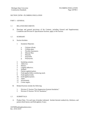
I. IntroductionTHe Advanced Stirling Radioisotope Generator (ASRG) is under development by the Department of Energy andLockheed Martin Space Systems Company. It is comprised of two Advanced Stirling Convertors (ASC) whichare being developed by an integrated team of Sunpower and thetechnology development effort in 2003 and has since evolved through progressive convertor builds and successfultesting to demonstrate high conversion efficiency, low mass, and capability to meet long-life Radioisotope PowerSystem (RPS) requirements. The objective of the Athermal energy from the Plutonium-238 General Purpose Heat Source (GPHS) to the environment and to act as apassive safety device in the event of single convertor stoppage. In the latter case, the insulation would permanentlyshrink to allow a sufficient heat leak, ensuring that the iridium cladding in the GPHS never exceeds its designtemperature.Preliminary studies have been done on the use of multilayer insulation (MLI) in the ASRG. These studies showthe potential benefits of MLI for space vacuum applications in reducing generator size and increasing specific power(W/kg) as compared to the baseline Microtherm HT (Microtherm, Inc.) insulation. Thermal losses from theMicrotherm HT insulation currently used in the ASRG are estimated to exceed 25% (62.3 W th on the ground (1 atmArgon)) and 15% (37.8 Wth) in a vacuum of the total 244.0 Wth generated by the GPHS1. Studies show these lossescan be reduced through the substitution of MLI for the Microtherm HT currently used in the ASRG. A schematic ofthe ASRG and its insulation package is shown in Fig. 1.Insulation PackageFigure 1. Advanced Stirling Radioisotope Generator featuring insulation package.The MLI consists of several layers of closelyOuter coverspaced, highly reflective shields, or foils, which areFoilsplaced perpendicular to the heat flow direction. TheseAdditionallayerslow emissivity foils provide a thermal high resistanceSpacersto radiative heat transfer between layers. To avoiddirect contact between the foils, and therefore heatInner coverconduction between the sheets, low-conductivity, nonFigure 2. Sketch of a typical multilayer insulation.metallic spacers are used. A sketch of a typicalFoils are denoted by a solid line and spacers by amultilayer insulation is shown in Figure 2.dashed line.The theoretical thermal conductivity of MLI (usingnickel foils and ZrO2 spacers) has been found to be approximately two orders of magnitude less than that of fibrousbulk insulations at 1000 C in a vacuum environment2. To help better quantify the characteristics and potentiallyincrease the temperature range of state-of-the-art MLI, a development effort is underway to expand our experimentaltest rig capabilities, identify, test and analyze candidate materials, and optimize data collection and thermalmodeling at GRC. This effort is key in that insulation materials directly benefit thermal management and couldimprove performance of RPS for future science missions.2American Institute of Aeronautics and Astronautics
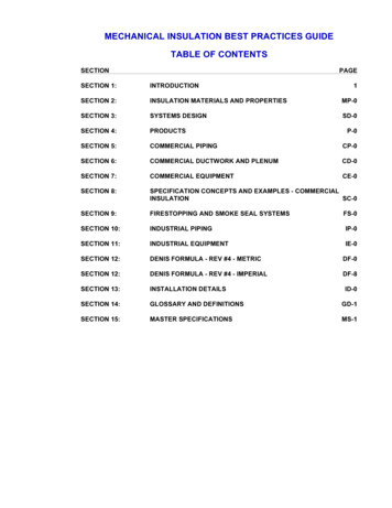
II. Experimental TestingA. Insulation Test Rig and Test MethodologyThe design goal of the experimental test rig was to establish onedimensional heat flow through an insulation sample to compare MLIcandidates including foil/aerogel hybrid insulations for future RPS. Asecondary goal was to configure the rig for relatively convenientinterchangeability of the test samples and addition of instrumentationas needed. The MLI rig and test station can be seen in Fig. 3.The test rig consists of a heat source and a vertical MLI stacksurrounded by a Microtherm Moulded Pipe Section (MPS) holder.The heat source is a HeatWave Laboratory Model #102104 heaterenclosed in a custom housing. The inside diameter (ID) of the MPSholder slips over the outside diameter (OD) of the custom heaterhousing and encloses the heater and MLI stack. The MPS holderinsulates the MLI stack and the heater, minimizing heat loss in theradial direction, as well as optically encloses the test sample. TheMPS holder is made of a microporous silica insulation with ais wrapped in E-Glass cloth foreasy handling. Its rated thermal conductivity in air is 0.034 W/mK at amean temperature of 800 C, the highest temperature tested by themanufacturer3. The heater, which is made of tungsten, has a threelayer heat shield on the back side to minimize heat loss in thedownward direction. Its heating elements are covered by amolybdenum plate that acts as a heat spreader. The heater is rated tooperate at 1100 C continuously in vacuum. Installation of the MPSholder around the tungsten heater is shown in Fig. 4. The vertical MLI Figure 3. MLI rig and test station.test sample stack is constructed by alternately layering either ceramic fabric or paper spacers with or without aerogelimpregnation between metal foils.Figure 4. MPS holder installed around tungsten heater in MLI Rig. Image on left shows MPS holderbeing installed around the heater. Image on right shows MPS holder in its testing configuration.3American Institute of Aeronautics and Astronautics
An RdF Model 27036-3 heat flux sensor withintegrated Type T thermocouple was adhered to thetop foil in the MLI stack using OMEGABOND 200high thermal conductivity two-part epoxy. Thetemperature and heat flux of the outside of the holderand backside of the heater were measured using RdFModel 27036-1 and 27036-3 heat flux sensors,respectively. The heat flux sensors are limited to amaximum operating temperature of 260 C. Thebottom heat flux sensor is consistently the hottest andtherefore limits the maximum reference temperatureof the test rig to approximately 625 C. Figure 5shows the heat flux sensor affixed to the outside of theMPS holder.Figure 5. Heat flux sensor installed on the side of theThe entire assembly was mounted in a stainlessMicrotherm MPS holder.steel bell jar. The bell jar is evacuated using aLeybold Model TMP 1000 C turbopump to a pressureless than 8 x 10⁻⁶ torr to ensure that convection does not play a significant role in the heat transfer.The top of the bell jar is water cooled to maintain a constant sink temperature of 20 C. The un-cooled sides ofthe bell jar that are outside of the view factor of the top foil minimally heat up during testing. The maximumtemperature of these sidewalls was measured to be less than 35 C by a combination of reference thermocouples andIR imaging of the exterior of the sidewalls.An Ohio Semitronics PC8-002-01D DC watt transducer and a variable frequency AC watt transducer measuresthe electrical power supplied to the heater and permits a power balance calculation and determination of thepotential heat losses through thermal shorts and other means not accounted for by the three heat flux sensors, e.g.,loss through the copper leads for the heater power and loss through the thermocouples.The signals from the sensors were collected using ICP DAS Model I-7011 data acquisition (DAQ) modules. Themodules convert the analog signals to digital signals and send the data over a local area network to the DAQcomputer. A custom-written DAQ program is utilized to record data every 60 seconds. This interval is sufficient togive adequate statistical data on the measurements.During testing, data were considered to be at steady state and test conditions at thermal equilibrium when the testenvironment pressure was less than 8 x 10⁻⁶ torr and the temperature of the top foil remained constant within 3 Cper hour. The top foil thermocouple was used to determine thermal equilibrium since it was observed to be the lastof the test environment thermocouples to reach thermal equilibrium. The thermocouple that defined the referencetemperature, or test rig temperature, during testing is located above the heater and below the hottest (bottom) foil.B. Candidate MaterialsThe Advanced Stirling Convertor has an upper temperature limit of approximately 850 C based on material liferequirements. The ASCs in the Advanced Stirling Radioisotope Generator currently operate below this maximumtemperature due to improved overall power output (reduced heat losses through the insulation) at 760 C. Using theASC material limits of a nickel heat acceptor at 850 C temperature, the temperature of the inner surface of theinsulation is typically 100 C greater, or 950 C. The candidate MLI foils and spacers under consideration for testingmust perform effectively within this temperature range. The candidate foils, along with their respective materialproperties, are listed in Table I.MetalTable I. Candidate foils for MLI testing.Emissivity/NoteTemp ( C)0.14-0.30 / 727 2930unoxidizedTantalumMeltingPoint3000 CNickelNiobium2Molybdenum1170 C(eutectic)2617 CNi 0.05 0.19 /38 1000Nb 0.12 / 10000.06 0.18 /38 1093unoxidized onlyfirst layer NbunoxidizedNickel 0.0258 / 25Niobium 0.052 / 25TBDGold1063 C0.02 0.03 / 38 1093PolishedTBD4American Institute of Aeronautics and AstronauticsMeasured Emissivity/Temp ( C)0.0922 / 25
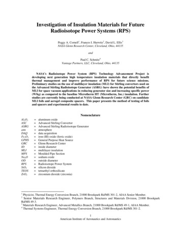
Emissivity testing was performed atroom temperature on the tantalum,nickel and niobium candidate foils toverify their known emissivity values.The measurements were obtained usingan Infrared Reflectometer Model DB100from Gier Dunkle Instruments, Inc.Reflectivity was measured and recordedat various locations on each sample,allowing us to obtain the averageemissivityofeachfoil. Thereflectometer was calibrated to the goldand black standard values of R 0.976and 0.089, respectively. These measuredemissivity values are also shown inTable I.The candidate spacer materialsunder consideration, which haveadvanced insulating properties comparedto zirconia spacers that have been usedFigure 6. Spectral properties of APA-2 paper with aerogel.in the past, include APA-2 aluminapaper (Zircar Ceramics, Inc.), Astroquartz silica fiber fabric (JPS Composite Materials), Fiberfrax 972AH aluminapaper (Unifrax, LLC) and Saffil paper (Saffil, Ltd.). As shown in Fig. 6, spectral properties of the candidate spacermaterials are a primary factor in material selection for testing. Further consideration includes commercialavailability and physical characteristics such as thickness and density. The physical and thermal characteristics, aswell as composition, of the current candidate spacers are shown in Table II and their respective microstructures areshown in Figs. 7 10.Characterization of insulation materials has substantially progressed and material scientists at Glenn ResearchCenter are presently studying aerogel materials with increased temperature capability and lower densities comparedwith state of the art polymer-based insulating materials. Composites such as those currently under considerationimpregnated with aerogel offer potential as spacers between MLI foils.Ceramic ReinforcementAPA-2 PaperTable II. Candidate spacers for MLI testing.ThicknessComposition (%)DensityUpper Use(mm)(g/cc)Temperature1.250.111650 C86 Al2O3, 10 SiO2, 4 other oxidesFiberfrax 972AH0.80.1921176 CAstroquartz (503 plainweave without binder)Saffil Paper0.112.21070 CFigure7.APA-2microstructure0.5, 1.00.50.7Figure 8. Fiberfrax972AH microstructure1600 C47-52 Al2O3, 48-53 SiO2, 0.5 Na2O, 0.5 Fe2O399.99 SiO295-97 Al2O3, 3.0-5.0 SiO2, 0.5 traceelementsFigure 9. Astroquartzfabric microstructure5American Institute of Aeronautics and AstronauticsFigure 10. Saffil papermicrostructure
Figure 11. Microstructure of the as-supercritically dried aluminosilicate aerogel before andafter 20 minutes of exposure at 1100 C. Image on left shows before drying (surface area is 415m2/g). Image on right shows after drying (surface area is 266 m2/g).Aerogels are mesoporous structures with interconnecting pores and high surface areas; the pore walls arecomprised of thin struts that provide a lengthy and tortuous path limiting solid conduction from foil to foil. In anapplication with any gaseous environment, gas convection is limited by the small-scale pore structure; in bothatmosphere and vacuum, extinction of radiation heat transfer takes place by absorption 4 and is wavelength andtemperature dependent. The effective thermal conductivity also is expected to be influenced by the emissivity of theadjacent foils5.Although numerous studies have been conducted on silica aerogels,aerogels can be synthesized using a wide variety of elements, and theirupper use temperature is limited by their chemical composition. Hence,polymeric aerogels are limited by the decomposition temperature of theparticular polymer ( insulating. The group at NASA Glenn Research Center has developedaluminosilicate aerogels which maintain high surface areas andmesoporous structures to temperatures of 1100reaction of boehmite and tetraethyl orthosilicate (TEOS), in which thesurface area and pore structure can be controlled by the choice ofboehmite precursor and the synthesis parameters 6,7. The aluminosilicateFigure 12. Aerogel compositeaerogels in the present study utilize an aluminum to silicon ratio of 3 toreinforced with APA-2 alumina1, the ratio found in mullite.paper.Microstructure of the as-supercritically dried aerogel, and the sameaerogel after 20 minutes of. 11. Thesurface area decreases from 415 to 266 m 2/g on exposure, and the porevolume decreases from 0.67 to 0.44 cm3/g. A mesoporous structure ismaintained, with the average pore diameter changing from 7.44 to 8.15nm.Because of the fragile nature of the aluminosilicate aerogelmonoliths, our team at GRC has developed techniques for incorporatingthese into composites, which can be reinforced using ceramic fabrics,papers, or felts. The work presented here focuses on the use of APA-2alumina paper. Composites also have been fabricated using Astroquartzsilica fiber fabric or Fiberfrax 972AH alumina paper. The compositesFigure 13. Microstructure of APA-2remain flexible (Fig. 12), which would be advantageous in forming anwith aerogel composite showing goodMLI around the GPHS. The APA-2 composite has a density of 0.15wetting of aerogel to fibers.33g/cm , as compared with 0.3428 g/cm for Microtherm HT. Thealuminosilicate aerogel bonds well to the alumina fibers (see Fig. 13), averting the spalling of aerogel particles seenin some commercial materials.6American Institute of Aeronautics and Astronautics
C. ModelingA Thermal Desktop model of the insulation sampleand surrounding environment was created to estimate thethermal performance of the test foils (see Fig. 14). Themodel includes the following test rig components; foils withtemperature dependent properties, spacers, heat source andtest chamber (approximated as a single isothermalboundary).Currently, poor correlation exists between the test resultsand the model, therefore, modification of both the test rigand the model are underway. Heat losses, such as edgeeffects (radiation from the edges of the MLI stack), werediameter).Several heat transfer paths and mechanisms can stronglyinfluence the model predictions and associated uncertaintyFigure 14. MLI model results usingand error propagation. One testing attribute beingThermal Desktop .investigated is to experimentally determine the effect ofspacer thickness on MLI performance. Thick or multiple spacer layers allow for the placement of thermocouplesbetween foil layers with minimum physical perturbation of the foils. Test runs are also underway withthermocouples at only the hot and cold sides of the stack as well as each layer of the stack to evaluate the influenceof radial heat transfer along the thermocouple leads. Once the heat transfer paths are identified, the MLI test rig willbe redesigned in an attempt to mitigate heat leaks, improve data fidelity and reduce associated error. An explodedview of the current test setup, generated through modeling tools, is shown in Fig. 15 with respective callouts inTable III.Figure 15. Exploded view of the primary test section components and MLI test sample.Table III. Locations of the primary test section components and MLI test sample as shown in Fig. 15.CalloutDescription1Heater assembly2MPS holder3Foil4Spacer7American Institute of Aeronautics and Astronautics
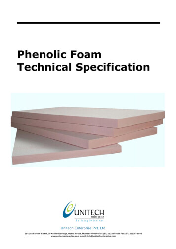
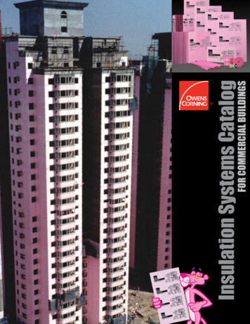
III. Experimental ResultsA. Tantalum Foils with APA-2 Alumina PaperThe first multilayer insulation run consisted of tantalum foils and APA-2 alumina paper spacers. The thicknessof the MLI stack was approximately 0.5 Temperatures within the MLI test rig were increased by approximately50 C every 12 24 hours until the data were considered to be at steady state and test conditions at thermalequilibrium (pressure was less than 8 x 10 -6 torr and temperature of the top foil remained constant within 3 C perhour).As seen in Fig. 16, the maximum operating temperature that can be reached with this foil and spacercombination is approximately 600 C. This is because the heat flux sensors that were utilized are limited to amaximum temperature of 260 C. The bottom heat flux sensor near the heater is consistently the hottest andtherefore limits the maximum reference temperature of the test rig to approximately 625 C.Figure 16. A typical time versus temperature plot for the tantalum foils with APA-2 alumina paper. The dataat maximum test rig temperature is circled.B. Tantalum Foils with APA-2 Alumina Paper Impregnated with Aluminosilicate AerogelThe subsequent MLI run consisted of five tantalum foils and eight APA-2 alumina paper spacers impregnatedwith aluminosilicate aerogel. The test rig conditions remained the same as the previous test, and the maximumtemperature reached was approximately 620 C. Test results of the tantalum foils and APA-2 with aerogel weresimilar to tantalum foils and APA-2 alone. The exception was that the temperature of the top (coldest) tantalum foilwithin the stack was approximately 40(at a test rig temperature) when the APA-2 paper wasimpregnated with aerogel compared with APA-2 paper alone (see Fig. 17).indicated that the composite spacer with aluminosilicate aerogel reduced heat transfer compared to the compositespacer without aerogel. Further testing and analysis is required to confirm repeatability of the results and todetermine the basis for the temperature difference.8American Institute of Aeronautics and Astronautics
Figure 17. Comparison of tantalum foils with APA-2 paper and tantalum foils with APA-2 paper withaerogel . The blue plot represents the tantalum/APA-2 temperatures and the red plot represents the tantalum/APA2 with aerogel temperatures. The x-axis displays reference temperatures and the y-axis displays the coldest foiltemperature (top of MLI stack).IV. ConclusionInsulation materials have a significant effect on decreasing the thermal losses and increasing specific power(W/kg) of radioisotope power systems. To help better quantify the characteristics and potentially increase thetemperature range of state-of-the-art MLI, a development effort is underway to expand our experimental test rigcapabilities, identify, test and analyze candidate materials, and optimize data collection and thermal modeling atGRC. Heat flow through insulation samples was achieved in the newly-developed MLI test rig and thermalmeasurement methods and predictions are progressing. Characterization of insulation materials has substantiallyadvanced and aerogel materials with increased operating temperature and decreased density are being studied for useas composite spacers in MLI. Future testing will consider foil/spacer combinations that are suitable in hightemperatures, can remain flexible to form an effective MLI around the General Purpose Heat Source of the ASRG,and are thin and low in density to potentially reduce generator size and increase specific power as compared to thebaseline Microtherm HT insulation.AcknowledgmentsThis work is funded through the NASA Science Mission Directorate. Any opinions, findings, conclusions orrecommendations expressed in this article are those of the authors and do not necessarily reflect the views of theNational Aeronautics and Space Administration. The authors wish to acknowledge the people who made this effortpossible including Katie Shaw for providing considerable analytical and modeling guidance; Haiquan Guo for hermaterials expertise and composite fabrication; Adrienne Veverka, Jesse Bierer and Grant Feichter for their technicaldedication to our experimental testing; Don Jaworske for enabling our emissivity testing; and TerMason and Duane Beach for supporting this effort under the Radioisotope Power System (RPS) program.9American Institute of Aeronautics and Astronautics
References1Thermal DesktoProceedings of the Tenth International Energy Conversion EngineeringConference (IECEC 2012), Atlanta, GA, August 2012, AIAA 2012-4060.2-Foil Insulation to the Brayton Isotope Power System and Conceptual Designof MultiTE420910076, June 1976.3Promat High Performance Insulation Microtherm MPS Moulded Pipe Section brochure ets/TDS MICROTHERM MPS V1-EN.pdf.4Heinemann, U., R. Caps, et al. (1996). "Radiation-Conduction Interaction: An Investigation on Silica Aerogels." Int. J. HeatMass Transfer 39(10): 2115-2130.5Scheuerpflug, P., R. Caps, et al. (1985). "Apparent Thermal Conductivity of Evacuated SiO2-Aerogel Tiles under Variationof Radiative Boundary Conditions." Int. J. Heat mass Transfer 28(12): 2299-2306.6Hurwitz, F. I., H. Guo, et al. (2010). Tailoring of Boehmite-Derived Aluminosilicate Aerogel Structure and Properties:Influence of Ti Addition. MRS Fall Meeting, Boston, MA, Materials Research Society.7Hurwitz, F. I., H. Guo, et al. (2012). "Influence of Ti Addition on Boehmite-Derived Aluminum Silicate AErogels:Structure and Properties." J Sol-Gel Sci Technol 64(3): 756-764.10American Institute of Aeronautics and Astronautics
Microtherm HT insulation currently used in the ASRG are estimated to exceed 25% (62.3 W th on the ground (1 atm Argon)) and 15% (37.8 W th) in a vacuum of the total 244.0 W th generated by the GPHS 1. Studies show these losses can be reduced through the substitution of MLI for the Microtherm HT currently used in the ASRG. A schematic of