Transcription
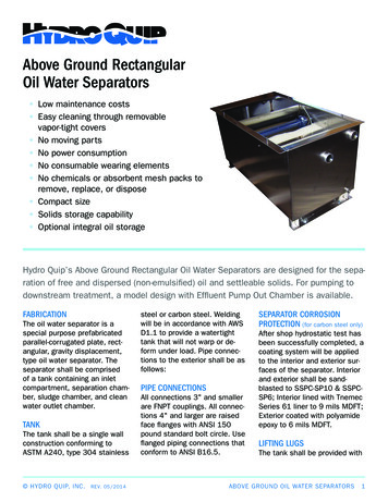
Above Ground RectangularOil Water Separators Low maintenance costs Easy cleaning through removablevapor-tight covers No moving parts No power consumption No consumable wearing elements No chemicals or absorbent mesh packs toremove, replace, or dispose Compact size Solids storage capability Optional integral oil storageHydro Quip’s Above Ground Rectangular Oil Water Separators are designed for the separation of free and dispersed (non-emulsified) oil and settleable solids. For pumping todownstream treatment, a model design with Effluent Pump Out Chamber is available.FABRICATIONThe oil water separator is aspecial purpose prefabricatedparallel-corrugated plate, rectangular, gravity displacement,type oil water separator. Theseparator shall be comprisedof a tank containing an inletcompartment, separation chamber, sludge chamber, and cleanwater outlet chamber.TANKThe tank shall be a single wallconstruction conforming toASTM A240, type 304 stainless HYDRO QUIP, INC.REV. 05/2014steel or carbon steel. Weldingwill be in accordance with AWSD1.1 to provide a watertighttank that will not warp or deform under load. Pipe connections to the exterior shall be asfollows:PIPE CONNECTIONSAll connections 3" and smallerare FNPT couplings. All connections 4" and larger are raisedface flanges with ANSI 150pound standard bolt circle. Useflanged piping connections thatconform to ANSI B16.5.SEPARATOR CORROSIONPROTECTION (for carbon steel only)After shop hydrostatic test hasbeen successfully completed, acoating system will be appliedto the interior and exterior surfaces of the separator. Interiorand exterior shall be sandblasted to SSPC-SP10 & SSPCSP6; Interior lined with TnemecSeries 61 liner to 9 mils MDFT;Exterior coated with polyamideepoxy to 6 mils MDFT.LIFTING LUGSThe tank shall be provided withABOVE GROUND OIL WATER SEPARATORS1
properly sized lifting lugs forhandling and installation.COVERSThe tank will be provided withvapor-tight covers for vaporcontrol. Gas vents and suitableaccess openings to each compartment will be provided. Thecovers shall be constructed ofmarine grade aluminum and willbe fastened in place. A gasketshall be provided for vapor tightness. 3 8" bolts and threadedknobs will be provided for coverattachment.INLET COMPARTMENTThe inlet chamber shall becomprised of a non-clog diffuserto distribute the flow across thewidth of the separation chamber. The inlet compartment shallbe of sufficient volume to effectively reduce influent suspendedsolids, dissipate energy andbegin separation. The media willsit elevated on top of a sludgebaffle.SEPARATION CHAMBERThe oil separation chambershall contain the appropriatecoalescing media specific mediaspecific to your application. Themedia when installed in crossflow OWS shall meet US EPAMethod 1664 Rev. A and alsoEuropean Standard 858-1 for oilwater separators.BAFFLESAn oil retention, underflow weir,and overflow weir will be provided. Underflow weir shall be positioned to prevent re-suspensionof settled solids.SLUDGE BAFFLEThe sludge chamber shall belocated prior to the coalescingcompartment for the settling ofany solids. It shall also preventany solids from entering theclean water chamber.skimmer for gravity decantingof the separated oil to an external product storage tank or anoptional integral product storage tank. Other various types ofskimmers can be provided as anadditional option.CLEAN WATER CHAMBERThe tank will be provided witha clean water chamber, whichallows the water to leave theseparator by gravity flow throughthe clean water outlet port.For models using Effluent PumpOut Chamber, water will leaveseparator by pumped flow. Thechamber will be of sufficient volume to turn pump on/off.VENTSAppropriately sized vents will beprovided.OIL SKIMMERThe oil separation chamber willbe provided with a rotating pipeABOVE GROUND SEPARATORS SIZESEstimated sizes based on standard flow rates,which is dependent on the type of oil.Configurations can be modified to satisfy your sitespecific requirements.Above Ground OWSFlow RateSizeAGS Seriesup to 20 gpm4' longAGM Series20–60gpm5' long35–2000gpm6'–20' longAG Series HYDRO QUIP, INC.REV. 05/2014ABOVE GROUND OIL WATER SEPARATORS2
AG MODELSPECIFICATIONS*Dimensions are approximate and flow rates are dependent on the type of oil, media, and temperature in your application.ModelFlow Rate (GPM)DiameterWidthLengthHeightCapacity 0"124"216"112"12117AGS SERIESAGM SERIESAG SERIESAG-9-1H HYDRO QUIP, INC.REV. 05/2014ABOVE GROUND OIL WATER SEPARATORS3
AG MODEL WITH EFFLUENT PUMP OUT CHAMBERSPECIFICATIONS*Dimensions are approximate and flow rates are dependent on the type of oil, media, and temperature in your application.Capacity(GAL)Clean WaterChamber delFlow GM-1SS-30V3–11AGM-2SS-60VAGS SERIESAGM SERIESAG SERIES HYDRO QUIP, INC.REV. 05/2014ABOVE GROUND OIL WATER SEPARATORS4
AG ModelOPTIONAL OILSTORAGE TANK*AGS and AGM models may differ from below.PLANRIGHT SIDE VIEWELEVATIONAG Model with Effluent Pump Out ChamberEFFLUENT PUMPOUT CHAMBER*AGS and AGM models may differ from below.OPTIONAL OILSTORAGE TANKRelated ModelsFor collecting settleable solids and DNAPL, see Hydro Quip's Hopper Oil Water Separator.Whether an off-the-shelf unit or customized equipment, we'll help youdetermine the best solution for your application and site-specific needs.508-399-5771508-399-5352108 Pond St, Seekonk, MA 02703TEL:FAX: HYDRO QUIP, INC.REV. omABOVE GROUND OIL WATER SEPARATORS5
The oil water separator is a special purpose prefabricated parallel-corrugated plate, rect-angular, gravity displacement, type oil water separator. The separator shall be comprised of a tank containing an inlet compartment, separation cham-ber, sludge chamber, and clean water outlet chamber. TANK The tank shall be a single wall