Transcription
6th Pipeline Technology Conference 2011Enhanced Pipeline Monitoring with Fiber Optic SensorsJochen Frings,ILF Consulting Engineers, Germanyjochen.frings@ilf.comAbstractPipelines are efficient, highly reliable and safe means of transportation. However, although thenumber of leaks could be reduced since the early 70’s of the last century due to improved designand maintenance procedures as well as improved materials, leaks still appear. Most of these areoriginated by external causes such as digging excavators or slope movements despite intensivepipeline right of way surveillance by foot, car and out of the air.These events are a clear sign for a monitoring gap. Due to the highly distributed nature of pipelineswith classical technology very high investments for point sensors including power andcommunication facilities would have been necessary to allow complete coverage with real timemonitoring capabilities along the pipeline route.The technical evolution of fiber optic sensing technologies allows closing large parts of thismonitoring gap. With a maximum active sensor length of up to 30 kilometer and local resolutiondown to one meter these distributed fiber optic sensors are apt to detect various external leakcauses and actual leak locations by sensing temperature, strain and vibrations and even sound.After a short introduction to the technical approaches for distributed fiber optic sensing, anoverview on pipeline related applications in the field of leakage detection, third party activitymonitoring, ground movement detection and integrity monitoring will be presented.Finally insight to some engineering aspects of fiber optic sensing applications will be given.1INTRODUCTIONPipelines are part of the backbone for modern communities’ lifestyle and areabsolutely indispensable for transportation of water, gas, oil and all kinds ofproducts.Faults in these systems do not only result in service outages and financial losses butbear the potential of spillages causing environmental pollution or even disastrousaccidents.Due to this, governments, engineering companies and industry associations havedeveloped design, operation and maintenance standards for pipelines (e.g. TRFL(19) in Germany) based on which the number of leaks could be reduced drasticallyPage 1 of 12
PTC 2011, Enhanced Pipeline Monitoring With Fiber Optic Sensors, J.Fringssince the 60’s and early 70’s of the last century. As a result pipelines today arehighly reliable and safe means of transportation.However leaks and disastrous events still appear. Statistically about 50% of all leakswere caused by third party activities according to the European gas and oiltransportation industries’ recent yearly reports (1) and (2) followed by construction /material failure, corrosion and ground movement.In conclusion most leaks could be avoided, if the third party activities could bedetected in time to intervene before the actual leak appears. Despite often massiveefforts to monitor the pipeline’s right of way by walking, driving and flying along theright of way complete coverage of the pipeline right of way with real time monitoringequipment has been impossible for a long time. This is because of the prohibitivecost for installation, operation and maintenance of literally thousands of pointsensors like vibration or motion detectors and video cameras which would have to beinstalled including power supply and communication facilities along the pipeline routewith classic technology.These and many more issues can be resolved with the help of distributed fiber opticsensor cables, which are sensible over their complete length up to the range of 30kilometers and which are able to detect temperatures, strain, vibration and soundwith high location accuracy and absolute resolution. Since fiber optic cables areinsensitive to EMC, designed for harsh environments and independence of additionalfield power supply or additional communication installations they are optimally suitedfor highly distributed pipeline monitoring applications.Based on these advantages distributed fiber optic sensing has been appliedsuccessfully in a variety of applications already and thus can be considered to be afield proven technology.However, the technical evolution of distributed fiber optic sensing is still ongoing.New products with improved sensing technology and new signal analysis algorithmsallow in combination with permanently increasing computing performance highersensibility, detection speed and thus new applications.In the following a short introduction to the distributed sensing technology will beprovided, before an overview on several applications of the technology is presentedand some engineering aspects are discussed.2FIBER OPTIC CABLES ARE DISTRIBUTED SENSORSFiber optic cables are standard equipment for transmission of voice, video and otherdata and are frequently installed along pipelines and often used to enablecommunication between and remote control of individual stations of the system.Page 2 of 12
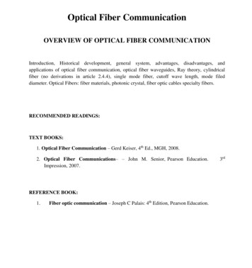
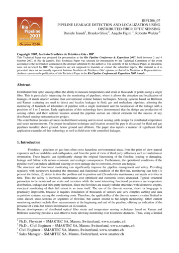
PTC 2011, Enhanced Pipeline Monitoring With Fiber Optic Sensors, J.FringsThe same standard optical fibers (typically single mode) are suitable to measureseveral physical effects with high absolute and local accuracy.2.1ScatteringFiber optic cables are typically designed such that scattering effects are minimized tomaximize transmission distance and data rate. However, it could be shown thatsome scattering effects of injected laser light depend on the fiber optic cable ambientconditions (temperature [T], strain [ε]) (3) as shown in Figure 1.Figure 1: Scattering effects in fibre optic cables caused by temperature [T] or strain [ε], (3)1)Rayleigh scattering:Elastic scattering of light based on density and composition fluctuations withinthe cable material. Scattering itself is not sensible to ambient conditions, butused for fiber integrity sensing and interferometric sensing applications.2)Raman scattering:Inelastic scattering of photons due to molecular vibration within the fibermaterial. The magnitude of the molecular vibration and the scattered signal isinfluenced by the environmental temperature.3)Brillouin scattering:Based on time dependent density variations of the fiber material. Thewavelength of the scattered signal is depending on the ambient temperatureand the strain or vibration of the optical fiber.To measure the Raman and Brillouin scattering effects advanced and specializedoptical time domain reflectometers (OTDR) are applied. These measurementdevices send short laser pulses into the fiber and analyze the time-distance relatedreflection/scattering signals with regards to frequency and amplitude of the desiredscattering effect. In consequence it becomes possible to measure strain andtemperature along the fiber, as shown in Figure 2.Page 3 of 12
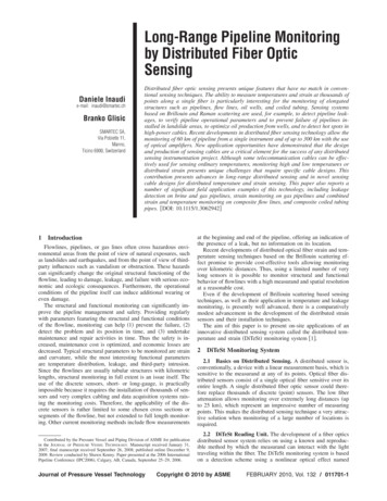
PTC 2011, Enhanced Pipeline Monitoring With Fiber Optic Sensors, J.FringsFigure 2: Temperature and strain profile along optical fiber (4)Multiple products are available on the market. Typical temperature resolution is inthe range of 0,10K, while strain resolution can be in the area of 20με, both with alocal resolution in the range of 1m, while the absolute ranges largely depend on thecable construction. In all cases improvement of resolution corresponds to increasedtime for measurement and hence both have to be adapted application specific.Maximum sensor lengths for single mode fiber based Raman and Brillouin systemstypically are in the range of 20 to 30 kilometers, while multi mode fiber based Ramansystems typically have a reach of up to 8 kilometersWhile for Brillouin scattering temperature measurement can be implemented withstandard telecom cable constructions (loose tube) which decouple the fiber fromexternal strain as much as possible, for strain measurements temperaturecompensation has to be implemented. This can be achieved by using two fibers inparallel: One coupled to e.g. the pipeline to measure strain changes; the other fiberinstalled nearby and strain relieved to measure the temperature.Based on strain sensing various vendors offer also detection of vibration (changingstrain).3.2. InterferometersFor more than a century interferometers have been a well known solution to detectvery small changes of distances and the interferometer principles have beensuccessfully applied to fiber optic measurement configurations since the early daysof fiber optics.With the advent of modern fiber optic components and using the constantlyimproving computing performance for improved measurement signal analysisresearch projects and several vendors developed configurations that can work asdistributed microphones/hydrophones with high sensibility and good locationaccuracy.For example a fiber optic configuration according to the Mach-ZehnderInterferometer can detect sound waves or vibrations by analyzing signal interferencePage 4 of 12
PTC 2011, Enhanced Pipeline Monitoring With Fiber Optic Sensors, J.Fringsbetween two separate sensor fibers (5) and thus can act as a hydrophone (seeFigure 3).Figure 3: System block diagram presenting fibre optic interferometerThe interferometer can manage a sensing distance up to 40 km and its sensibility isat least up to 3 m radius around the fiber optic cable.According to (18) another system sends two accurately timed pulses and analysesthe interference of the Rayleigh scattering signals and thus is able to detect sounds.Sensitive cable length of up to 50 kilometers is claimed to be possible.Intelligent signal analysis is necessary to identify and separate farming machines,underground construction works, digging, tapping and other events which are subjectof a specific training phase.Another approach to overcome the weak locating capabilities of standardinterferometers is described in (17) were an interferometer is combined with Brillouininstrument. While the interferometer allows precise analysis of the event, theBrillouin instrument allows to locate the event precisely.3PIPELINE APPLICATIONS FOR DISTRIBUTED FIBER OPTIC SENSORSBased on the above it becomes clear that distributed fiber optic sensors are almostideal for many types of pipeline monitoring applications and several of theseapplications have been implemented during recent years all over the industry.Unfortunately it is not possible to give a complete overview and thus the followingshould be considered as examples only.3.1Leak DetectionLoss of transported medium due to pipeline leaks typically results into one or more ofthe following detectable effects:1. Local cooling due to Joule-Thomson effect (high pressure gas pipelines)Page 5 of 12
PTC 2011, Enhanced Pipeline Monitoring With Fiber Optic Sensors, J.Frings2. Soil temperature change due to temperature difference between soil andemanated fluids and due to evaporation effects.3. Especially in high pressure applications the emanating medium generatesdetectable sounds.Based on Raman or Brillouin scattering effects the temperature changes can bedetected, if the medium temperature is different from the soil temperature. Hencedistributed temperature sensing has been reported to be applied for natural gas,brine, phenol, sulfur, LNG, crude oil and other mediums and allows detecting evenvery small leaks (for example (3),(6),(7)). Compared to the conventional intrinsicPipeline Monitoring methods this approach has the additional advantage to becompletely independent of any process conditions.Even the periodical opening and closing of small leaks in gas pipelines due tofreezing effects can be identified with modern signal analysis methods.For offshore pipelines the application of leak sound detection is reported in (6) basedon a Brillouin strain measurement system.Distributed temperature sensing is used in all cases to improve the performance ofcomputational monitoring systems. This is not only due to the fact that distributedtemperature sensing has been installed at pipelines which already hadcomputational monitoring systems. Although distributed temperature sensing is awell proven technology that has shown to be able to detect very small leaks in shorttime, it is very hard to calculate the minimum detectable leak size or to guarantee amaximum detection time which in many cases are necessary to receive pipelineoperation licenses.3.2Ground Movement Detection and Structural Health MonitoringGeohazards like earthquakes, landslides and surface subsidence result into groundmovement and thus put additional stress on the pipelines, tunnels and otherunderground infrastructures. Distributed fiber optic strain sensors have been appliedin two ways to identify the endangering ground movements: Strain sensing fibers have been attached directly to the pipeline walls tomeasure the walls’ strain changes and to conclude on the consequentialmovements and deformations (8), (9), (10). In case a sudden strain increaseis detected, the pipe internal pressure can be reduced to reduce the totalstress and such to reduce the risk and/or effects of a leak. Strain sensing fiber optic cables are installed in parallel and close to theinfrastructure (11). This method allows covering large route sections due tosimplified cable installation method.Page 6 of 12
PTC 2011, Enhanced Pipeline Monitoring With Fiber Optic Sensors, J.FringsWhile pipeline sections know to have an increased risk of ground movements havebeen monitored with point sensors already during recent years, distributed fiber opticmonitoring can be installed along longer stretches of the pipeline. Thus also strainchanges due to planned ground works (e.g. trenchless installation of crossingpipelines and cables) can be monitored.3.3Third Party ActivitiesThe majority of all reported pipeline leak incidents has been caused by third partyactivities including construction and agricultural works, illegal tapping and intentionaldamaging. By applying distributed strain sensing (e.g. (6),(7)) or interferometerbased hydrophones (e.g.(5), (18), (21)) along the pipeline or other buriedinfrastructure, it becomes possible to detect approaching heavy earth workingmachines, actual digging (manual or machine supported), metallic contact with thepipeline and other sound and vibration signals. For example the system installedalong the BTC pipeline (21) could detect a third party activity including manualdigging. Because knowing the exact location of the event, immediate response couldprevent illegal tapping and consequential environmental and financial damages evenduring test operation.3.4Fire DetectionDistributed temperature sensing with fiber optic cables is used as heat detector forfire detection (13) in tunnels. Because the cable is sensitive along its completelength and because the temperature can be detected within a wide range it becomespossible to determine the fire position and development very detailed. Inconsequence ventilation and other fire fighting measurements can be coordinatedefficiently.3.5Power Cable and Transformer MonitoringPower cable isolation (XLPE) typically is rated for an operating temperature of 90 oC.Especially in power cable tunnels, when cables are bundled and mounted to cabletrays it is possible that this temperature is exceeded in high load situations. To thisend distributed fibre optic temperature sensors have been installed inside the cableisolation (e.g. (14), (15)), so that a direct temperature assessment becomes possiblewith high local resolution and thus countermeasures can be initiated easily.Page 7 of 12
PTC 2011, Enhanced Pipeline Monitoring With Fiber Optic Sensors, J.Frings3.6Status Monitoring of Water MainsPre-stressed concrete cylinder pipes (PCCP) are widely used in water mains.However in several cases PCCP did not show to be as durable as expected, whichresulted in several water main ruptures with considerable damages and a largenumber of smaller defects resulting into water losses. It has been shown (16) thatthe stability of PCCP correlates with the number of broken wires inside the pipe. Asthe breaking wire emanates a special sound this can be detected by an acousticsensitive fibre optic sensor installed inside the pipeline. Based on the pipe book asoftware package can than count the number of broken wires and can issue analarm in case the total number of broken wires or the number of wires broken withina certain time period exceeds a limit.Since the wire break event is only very short the pulsed Brillouin based acousticdetectors often do not detect sufficient information for clear identification of the wirebreak event. On the other side interferometers such as Sagnac- or Michelsoninterferometer analyse the signal continuously and such receive all availableinformation about the wire break sound - but they are weak in locating the signal.Thus a combined interferometer and Brillouin detector is described in (17) and hasbeen applied to several water mains in the United States of America.3.7Pig Position DetectionSystems designed to detect sounds of third party activities are also apt to detect thesounds created by pigs according to e.g. (22).4SOME ENGINEERING ASPECTS OF DISTRIBUTED SENSINGSince standard telecom cables are optimized for long distance signal transmissionwith protection of all fibers against strain (e.g. jelly field tubes) or againstenvironmental influences (e.g. multiple sheath layers), for measurement purposesthese are not always the best solution. For example strain relieved fibers are notable to measure strain and thick multilayer sheaths increase measurement delay fortemperature. In consequence various measurement cable constructions areavailable in the market. For example there are cables with specialized profiles toallow gluing the cable to any type of structure such as steel bridges or concretetunnels. Other cables are specialized for high temperature measurements and more.Page 8 of 12
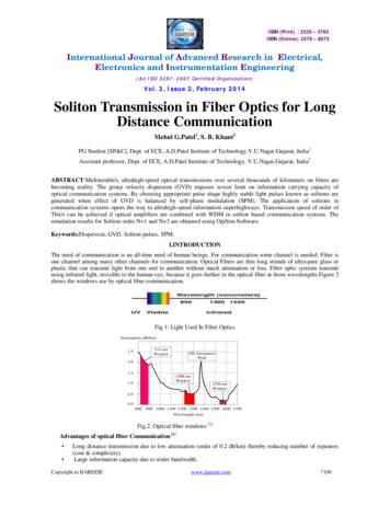
PTC 2011, Enhanced Pipeline Monitoring With Fiber Optic Sensors, J.FringsFigure 4: Application specific sensor location along pipelineOf course the sensor position decides about the correctness of the measurement.Typical locations of the sensor cables relative to for example a pipeline are indicatedin Figure 4. For liquid leak detection the sensor should be installed below the pipeand on top for leak detection of most gaseous mediums, while pipeline strainobviously can be measured only, if the fiber is directly bonded to the pipeline. Typicalgas and telecom cable positions are suitable for third party interference as well as forground movement detection. For different applications similar considerations apply.To achieve a clear leak detection signal at least 2 to 5 oK temperature differencebetween the fluid in the pipeline and the soil temperature around the sensor arerequired, although datasheets state to have accuracy down to 0,1 oK. It has to beproven that this minimum temperature difference can be guaranteed throughout thewhole year despite all seasonal temperature changes and for all pipeline operationstates to avoid blind periods.While this is normally no problem for e.g. high pressure gas pipelines (due to thestrong Joule-Thomson effect), detailed seasonal analysis of soil temperature profilesis necessary for typical crude and product pipelines, even in case the transportedmedium has a much higher temperature than the not influenced soil temperature.For simplification only a single season scenario (winter, operating pipeline) is shownin the figure below. It shows the results of our analysis for a crude oil pipeline underthe assumption of 33oC medium temperature and -10oC air temperature after severalweeks of continuous operation and allows estimation of the minimum necessarydistance between the pipeline wall and the sensor cable.Page 9 of 12
PTC 2011, Enhanced Pipeline Monitoring With Fiber Optic Sensors, J.FringsFigure 5: Soil temperature profile around oil pipeline (winter)For the required temperature difference a distance of more than half a meter fromthe bottom of the pipe has to be obeyed.The effectiveness of most distributed fiber optic sensor systems is based not only onthe sensor design and installation but also on the signal analysis program design.These pattern analysis mechanisms have to be trained carefully to ensure maximumdetection rates with minimum false alarm rates.5CONCLUSIONDistributed fibre optic sensing is a field proven technology for online monitoring oftemperature, strain, vibration and sound over long distances with high localresolution that is apt to improve pipeline integrity, safety and security considerably.Many different applications have already been implemented in the industry andconstantly ideas for new applications are being created.Although the basic principles for distributed fibre optic sensing have been known formore than two decades, the evolution of these technologies does not yet come to anend and especially during recent years improvements could be made by using theconstantly increased computing power for improved analysis of the measurements.Distributed fibre optic sensing systems installed along pipelines must be consideredas integral parts of pipeline instrumentation and application and installation of thesesystems have to be properly engineered to get the desired results.Page 10 of 12
PTC 2011, Enhanced Pipeline Monitoring With Fiber Optic Sensors, J.Frings6BIBLIOGRAPHY1. CONCAWE. Performance of European Cross Country Oil Pipelines, StatiscticalSummary of reported spillages. s.l. : www.concawe.org.2. EGIG. EGIG Report. s.l. : www.egig.nl.3. Pipeline Leakage Detection and Localization Using Distributed Fiber OpticSensing. D. Inaudi, B. Glisic, A. Figini, R. Walder. RIO Pipeline Conference, 2nd to4th October 2007.4. Waldner, R. Pipeline Leakage Detection and Localization Using distributed FiberOptic Sensing. Webinar. s.l. : Smartec, 2009.5. Future Fiber Technologies. Secure Link: Installation Overview. s.l. :www.fftsecurity.com, 2009.6. Sensornet. Digital Pipeline Integrity Monitoring System - Application Guide.7. Schlumberger. Integrated Pipeline Monitoring – Integrity. 2008.8. Long-range Pipeline Monitoring by Distributed Fiber Optic Sensing. D. Inaudi, B.Glisic. Calgary, Canada : s.n., 2006. 6th International Pipeline Conference.9. Earthquake Detection and Safety System for Oil Pipeline. L. Griesser, M. Wieland,R. Walder. December 2004, Pipeline & Gas Journal.10. Daniele, Inaudi and Branko, Glisic. Overview of Fibre Optic Sensing Applicationsto Structural Health Monitoring. 13th FIG Symposium on Deformation Measurementand Analysis. Lisboa : s.n., 2008.11. Omnisens. Pipeline Integrity Monitoring - Transandean Route, Case Study.12. Soga, Kenichi. Monitoring and Assessment of Civil Engineering Infrastructure. ASensory World: Novel Sensor Technologies and Applications. Cambridge : Universityof Cambridge, 2007.13. Liu, Z. and Kim, A.K. Review of Recent Development in Fire DetectionTechnologies. National Research Council Canada. 2003. NRCC-45699.14. Sensornet. Power Case Study - Power Cable Tunnel Monitoring. 2009.15. Glombitza, U. and Hoff, H. Fibre Optic Radar System for Fire Detection in CableTrays. 13th International Conference on Automatic Fire Detection. Duisburg : s.n.,2004.16. An Integrated Dynamic Approach to PCCP Integrity Management. J. Elliot, J.Stieb, M. Holley. 2006. Pipelines - Service to the Owner.17. Paulson, Peter O. Fiber Optic Sensor Method and Apparatus. US Patent7,564,540 B2 United States, 21 Jul. 2009.18. A. J. Rogers, S. E. Kanellopoulos, S. V. Shatalin. Detecting a Disturbance in thePropagation of Light in an Optical Waveguide. US Patent 7,872,736 B2, UnitedStates, 18. Jan. 2011.19. TRFL- Technische Regel für Rohrfernleitungsanlagen nach §9 Absatz 5 derRohrfernleitungsverordnung. 2010.Page 11 of 12
PTC 2011, Enhanced Pipeline Monitoring With Fiber Optic Sensors, J.Frings20. S. Scott, M. Barufett. Worldwide Assessment of Industry Leak DetectionCapabilities for Single and Multiphase Pipelines. Texas A&M University. s.l. : OTRCLibrary Number: 8/03A120, 2003.21. QinetiQ. QuinetiQ Optasense is selected to protect the BP-led Baku TbilisiCeyhan Pipeline, press release 29. Sept. 2010, s.l. www.qinetiq.com22. Optasense. Pipeline and Security Monitoring. s.l. www.quinetiq.com, 2010Page 12 of 12
PTC 2011, Enhanced Pipeline Monitoring With Fiber Optic Sensors, J.Frings Page 3 of 12 The same standard optical fibers (typically single mode) are suitable to measure several physical effects with high absolute and local accuracy. 2.1 Scattering Fiber optic cables are typically designed such that scattering effects are minimized to