Transcription
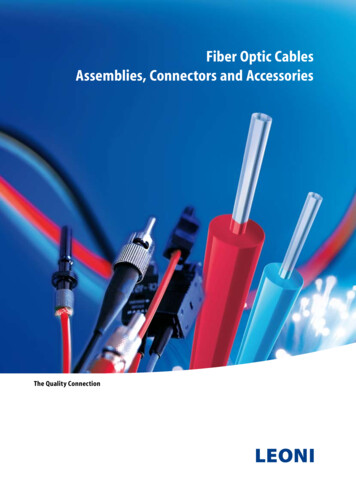
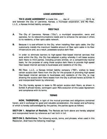
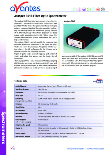
AvaSpec-3648 Fiber Optic SpectrometerThe AvaSpec-3648 Fiber Optic Spectrometers is based on theAvaBench-75 symmetrical Czerny-Turner design with 3648pixel CCD Detector Array. The spectrometer has a fiber opticentrance connector (standard SMA, others possible), collimating and focusing mirror and diffractional grating. A choiceof 16 different gratings with different dispersion and blazeangles enable applications in the 200-1100nm range. TheAvaSpec-3648 comes with a 16 bit AD converter, and USB2.0high speed interface.The AvaSpec- 3648 is especially suitable for measuring highresolution applications and thanks to the 10µsec electronicshutter has a wide dynamic range. An optional detector coating enhances the CCD performance for the UV range and adetector collection lens offers high sensitivity.Digital IO ports enable external triggering and control ofshutter and pulsed light sources from the Avantes line ofinstruments.The AvaSpec-3648 has a USB2 interface with fast data samplingof 270 spectra per second and data transfer in 3.7 msec andsupports analog in-and outputs as well. Optional Bluetooth (-BT) communication and an SD card for on-board saving ofAvaSpec-3648spectra can be added. The AvaSpec-3648-USB2 runs on USBpower and comes with AvaSoft-basic, a complete manualand USB interface cable. Multiple (up to 127) USB2 spectrometers with different detectors can be externally coupled(see section multichannel spectrometers, page 32).Technical DataOptical BenchSymmetrical Czerny-Turner, 75 mm focal lengthWavelength range200-1100 nmResolution0.025 –20 nm, depending on configuration (see table)Stray light 0.1%Sensitivity14,000 counts (16-bit AD)/µW -per ms integration time(AvaLight-HAL, 8 µm fiber)SpectrometersDetectorCCD linear array, 3648 pixelsSignal/Noise350:1AD converter16 bit, 1MHzIntegration time10 µsec – 10 minutesInterfaceUSB 2.0 high speed, 480 Mbps or RS-232, 115.200 bpsSample speed3.7 msec / scanwith on-board averaging26Data transfer speed3.7 msec / scanDigital IOHD-26 connector, 2 Analog in, 2 Analog out, 3 Digital in, 12 Digital out, trigger,synchronizationPower supplyDefault USB power, 350 mA. Or with SPU2 external 12VDC, 350 mADimensions, weight175 x 110 x 44 mm (1 channel), 716 gramsinfo@avantes.com www.avantes.com
Grating selection table for IRVISVISVISVISNIRNIRNIRNIRUseable 1050500-1050600-1100**600-1100Spectral range (nm) 600Blaze 0Order codeUAUBUCUDUEUFBBVAVBVCVDVENBNCIAIB* depends on the starting wavelength of the grating; the higher the wavelength, the bigger the dispersion and the smaller the range to select**please note that not all 3648 pixels will be used for the useable rangeResolution table (FWHM) for AvaSpec-3648Slit size (µm)Grating .04*0.07-0.10*0.11-0.16*0.2-0.3*0.4-0.6*0.9-1.4** depends on the starting wavelength of the grating; the higher the wavelength, the bigger the dispersion and the better the OSC-UBFiber Optic Spectrometer, 75 mm Avabench, 3648 pixel CCD detector, USB powered high speedUSB2 interface, incl AvaSoft-Basic, USB interface cable, specify grating, wavelength range andoptionsFiber Optic Spectrometer, 75 mm Avabench, 3648 pixel CCD detector, high speed USB2interface, incl. switch for USB powered USB2 or external power for RS232/BT, AvaSoft-Basic,USB interface cable, specify grating, wavelength range and optionsBluetooth interface for USB2 platform only, including antenna and switchInternal XXX MB SD card for on board data saving, for USB2 platform onlyDeep UV detector coating 150 nmDetector Collection lens to enhance sensitivity, Quartz, 200-1100 nmSlit size, please specify XX 10, 25, 50, 100, 200, 500 µmOrder sorting filter for 2nd order effects filtering, please specify YYY 375, 475, 515, 550, 600 nmOrder sorting coating with 590nm long pass filter for VA, BB ( 350nm) and VB gratings in AvaSpec-3648Order sorting coating with 350 and 590nm longpass filter for UA gratings in AvaSpec-3648Order sorting coating with 350 and 590nm longpass filter for UB or BB ( 350nm) gratings in AvaSpec-3648www.avantes.com info@avantes.com27SpectrometersORDERING INFORMATION
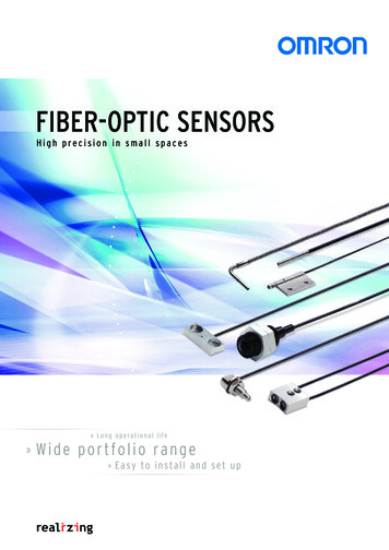
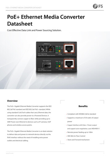
Introduction Fiber Optic SpectroscopyOptical spectroscopy is a technique for measuring lightintensity in the UV-, VIS-, NIR- and IR-region. Spectroscopicmeasurements are being used in many different applications,such as color measurement, concentration determination ofchemical components or electromagnetic radiation analysis.For more elaborate application information and setups,please see further the Application chapter at the end of thiscatalog.A spectroscopic instrument generally consists of entrance slit,collimator, a dispersive element, such as a grating or prism,focusing optics and detector. In a monochromator systemthere is normally also an exit slit, and only a narrow portionof the spectrum is projected on a one-element detector. Inmonochromators the entrance and exit slits are in a fixedposition and can be changed in width. Rotating the gratingscans the spectrum.Devices (CCD) Arrays and Photo Diode (PD) Arrays, enabled theproduction of low cost scanners, CCD cameras etc. The sameCCD and PDA detectors are now used in the Avantes line ofspectrometers, enabling fast scanning of the spectrum, without the need of a moving grating.Thanks to the need for fiber optics in the communicationtechnology, low absorption silica fibers have been developed.Similar fibers can be used as measurement fibers to transportlight from the sample to the optical bench of the spectrometer. The easy coupling of fibers allows a modular build-up of asystem that consists of light source, sampling accessories andfiber optic spectrometer.Advantages of fiber optic spectroscopy are the modularity andflexibility of the system. The speed of measurement allows inline analysis, and the use of low-cost commonly used detectorsenable a complete low cost Avantes spectrometer system.Development of micro-electronics during the 90’s in the fieldof multi-element optical detectors, such as Charged CoupledOptical Bench DesignFigure 1 Optical bench designSpectrometersThe heart of the AvaSpec fiber optic spectrometer is an opticalbench with 45, 50 or 75 mm focal length, developed in a symmetrical Czerny-Turner design (figure 1).Light enters the optical bench through a standard SMA905connector and is collimated by a spherical mirror. A planegrating diffracts the collimated light; a second spherical mirrorfocuses the resulting diffracted light. An image of the spectrumis projected onto a 1-dimensional linear detector array.6The optical bench has a number of components installedinside, allowing a wide variety of different configurations,depending on the intended application. The choice of thesecomponents such as the diffraction grating, entrance slit, ordersorting filter, and detector coating have a strong influence onsystem specifications. Sensitivity, resolution, bandwidth andstray light are further discussed in the following paragraphs.info@avantes.com www.avantes.com
How to configure a spectrometer for your application?1. Wavelength RangeIn the determination for the optimal configuration ofa spectrometer system the wavelength range is the firstimportant parameter that defines the grating choice. If youare looking for a wide wavelength range, we recommendto take an A-type (300 lines/mm) or B-type (600 lines/mm)grating (see Grating selection table in the spectrometerproduct section). The other important component is thedetector choice, Avantes offers 9 different detector typeswith each different sensitivity curves (see figure 5). ForUV applications the new 2048x14 pixel back-thinnedCCD detector, the 256/1024 pixel CMOS detectors orDUV- enhanced 2048 or 3648 pixel CCD detectors may beselected. For the NIR range 3 different InGaAs detectors areavailable.If you want to combine a wide range with a high resolution, a multiple channel spectrometer may be the bestchoice.2. Optical ResolutionIf you desire a high optical resolution we recommend topick a grating that has 1200 or more lines/mm (C,D,E orF types) in combination with a narrow slit and a detectorwith 2048 or 3648 pixels, for example 10 µm slit for thebest resolution on the AvaSpec-2048 (see Resolution tablein the spectrometer product section)3. SensitivityTalking about sensitivity, it is very important to distinguishbetween photometric sensitivity (How much light do I needfor a detectable signal?) and chemometric sensitivity (Whatabsorbance difference level can still be detected?)a. Photometric SensitivityIn order to achieve the most sensitive spectrometerin for example Fluorescence or Raman applicationswe recommend the 2048 pixel CCD detector, as in theAvaSpec-2048. Further we recommend the use of a DCLUV/VIS detector collection lens, a relatively wide slit(100µm or wider) or no slit and an A type grating. Foran A-type grating (300 lines/mm) the light dispersion isminimal, so it has the highest sensitivity of the gratingtypes. Optionally the Thermo-electric cooling of the CCDdetector (see product section AvaSpec-2048-TEC, page 30)may be chosen to minimize noise and increase dynamicrange at long integration times (60 seconds).www.avantes.com info@avantes.comFor optimal UV sensitivity we recommend the back-thinnedUV sensitive CCD detector, as implemented in the AvaSpec2048x14.For the different detector types the photometric sensitivity isgiven in table 4, the spectral sensitivity for each detector isdepicted in figure 5.b. Chemometric SensitivityTo detect two absorbance values, close to each other withmaximum sensitivity you need a high Signal to Noise (S/N)performance. The detector with best S/N performance is the2048x14 pixel back-thinned CCD detector, next to the 256/1024CMOS detector in the AvaSpec-256/1024. The S/N performancecan also be enhanced by averaging over multiple spectra.4. Timing and SpeedThe data capture process is inherently fast with detector arraysand no moving parts. However there is an optimal detector foreach application. For fast response applications, we recommend touse the AvaSpec- USB2 platform spectrometers. When datatransfertime is critical we recommend to select a small amount of pixels tobe transferred with the UBS2 interface. Data transfer time can beenhanced by selecting the pixel range of interest to be transmittedto the PC; in general the AvaSpec-128 may be considered as thefastest spectrometer with more than 8000 scans per second.The above parameters are the most important in choosing the rightspectrometer configuration, please contact our application engineers to optimize and fine-tune the system to your needs. On thenext page you will find a quick reference table 1 for most commonapplications, for a more elaborate explanation and configurations,please refer to the applications section in the back of this catalog.In addition we have introduced in this catalog application icons,that will help you to find the right products and accessories for yourapplications.Biomedical TechnologySpectrometersIn the modular AvaSpec design a number of choices have to bemade on several optical components and options, dependingon the application you want to use the spectrometer for.This section should give you some guidance on how tochoose the right grating, slit, detector and other options,installed in the AvaSpec.ChemistryColorimetryFood TechnologyInline Process ControlRadiometryThinfilm Analysis7
Table 1 Quick reference guide for spectrometer configurationApplicationAvaSpectypeGratingWL range (nm)CoatingSlitFWHMDCLResolution 48VD600-700-100.05-550-High 2048TECNC780-930-250.2X600-Thin -OSC-UANIR256-1.7 NIRA900-1750-505.0-1000-NIR256-2.2 NIRZ1200-2200-5010.0-1000-NIR256-2.5 rometers8info@avantes.com www.avantes.com
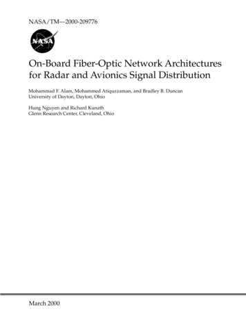
How to choose the right Grating?A diffraction grating is an optical element that separatesincident polychromatic radiation into its constituent wavelengths. A grating consists of series of equally spaced parallelgrooves formed in a reflective coating deposited on a suitablesubstrate.The way in which the grooves are formed separates gratingsin two types, holographic and ruled. The ruled gratings arephysically formed into a reflective surface with a diamond ona ruling machine. Gratings produced from laser constructedinterference patterns and a photolithographic process areknown as holographic gratings. In the Avaspec Spectrometersboth ruled and holographic gratings are used.The fiber optic spectrometer comes with a permanentlyinstalled grating that must be specified by the user. Furtherthe user needs to indicate what wavelength range needs toreach the detector. Sometimes the specified usable range ofa grating is larger than the range that can be projected onthe detector. In order to cover a broader range, a dual ortriple beam spectrometer can be chosen. Then master andslave(s) have different gratings. Similarly, a higher resolutionover a wide range can be achieved by using a dual or triplespectrometer.Different diffraction gratingsFor each spectrometer type, a grating selection table is shownin the Spectrometer Platforms section. Table 2 illustrates howto read the grating selection table. The spectral range to selectin Table 2 depends on the starting wavelength of the gratingand the number of lines/mm; the higher the wavelength, thebigger the dispersion and the smaller the range to select. InFigure 2 their efficiency curves are shown.When looking at the grating efficiency curves, please realizethat the total system efficiency will be a combination of fibertransmission, grating and mirror efficiency, detector and coatings sensitivities. In Figure 3 the grating dispersion curves areshown for the AvaSpec-2048.Please select Spectral range band-width fromthe useable Wavelength range, for example:grating UE (200-315nm)*the spectral range depends on the startingwavelength of the grating; the higher the wavelength, the smaller the range.For example grating UE (510-580 nm)www.avantes.com info@avantes.comThe order code is defined by 2 letters: the firstis the Blaze (U 250/300nm or UV for holographic, B 400nm, V 500nm or VIS for holographic, N 750nm, I 1000nm) and the secondthe nr of lines/mm (Z 150, A 300, B 600,C 1200, D 1800, E 2400, F 3600 lines/mm)9SpectrometersTable 2 Example of spectral range and gratings
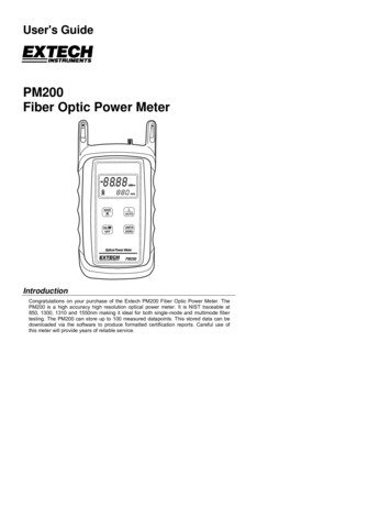
Figure 2 Grating Efficiency Curves300 Lines/mm Gratings600 Lines/mm Gratings1200 Lines/mm Gratings1800 Lines/mm Gratings2400 Lines/mm Gratings3600 Lines/mm GratingsSpectrometers10info@avantes.com www.avantes.com
300 Lines/mm Gratings600 Lines/mm Gratings1200 Lines/mm Gratings1800 Lines/mm Gratings2400 Lines/mm Gratings3600 Lines/mm GratingsUFwww.avantes.com info@avantes.com11SpectrometersFigure 3 Grating Dispersion Curves
How to select optimal Optical Resolution?The optical resolution is defined as the minimum differencein wavelength that can be separated by the spectrometer. Forseparation of two spectral lines it is necessary to image themat least 2 array-pixels apart. Because the grating determineshow far different wavelengths are separated (dispersed) at thedetector array, it is an important variable for the resolution.The other important parameter is the width of the lightbeam entering the spectrometer. This is basically the installed fixed entrance slit in the spectrometer, or the fiber corediameter when no slit is installed.The slits can be installed with following dimensions: 10, 25 or50 x 1000 µm high or 100, 200 or 500 µm x 2000 µm high. Itsimage on the detector array for a given wavelength will covera number of pixels. For two spectral lines to be separated, it isnow necessary that they be dispersed over at least this imagesize plus one pixel. When large core fibers are used the resolution can be improved by a slit of smaller size than the fiber core.This effectively reduces the width of the entering light beam.Installed Slit in SMA AdapterIn combination with a DCL-detector collection lens or thickfibers the actual FWHM value can be 10-20% higher than thevalue in the table. For best resolution small fibers and no DCLis recommended.The influence of the chosen grating and the effective width ofthe light beam (fiber core or entrance slit) are shown in thetables at the product information. In Table 3 the typical resolution can be found for the AvaSpec-2048. Please note thatfor the higher lines/mm gratings the pixel dispersion variesalong the wavelength range and gets better towards the longer wavelengths (see also Figure 3). The best resolution canalways be found for the longest wavelengths. The resolutionin this table is defined as F(ull) W(idth) H(alf) M(aximum),which is defined as the width in nm of the peak at 50% of themaximum intensity (see Figure 4).Graphs with information about the pixel dispersion can befound in the gratings section as well, so you can optimallydetermine the right grating and resolution for your specificapplication.Figure 4 Full Width Half MaximumTable 3 Resolution (FWHM in nm) for the AvaSpec-2048Slit size (µm)Spectrometers*12Grating s on the starting wavelength of the grating; the higher the wavelength, the bigger the dispersion and the better the resolutioninfo@avantes.com www.avantes.com
Detector ArraysCCD Detectors (AvaSpec-2048/3648)The Charged Coupled Device (CCD) detector stores the charge,dissipated as photons strike the photoactive surface. At theend of a controlled time-interval (integration time), theremaining charge is transferred to a buffer and then thissignal is being transferred to the AD converter. CCD detectorsare naturally integrating and therefore have an enormousdynamic range, only limited by the dark (thermal) currentand the speed of the AD converter. The 3648 pixel CCD has anintegrated electronic shutter function, so an integration timeof 10µsec can be achieved. Advantages for the CCD detector are many pixels (2048 or3648), high sensitivity and high speed.- Main disadvantage is the lower S/N ratio.UV enhancementFor applications below 350 nm with the AvaSpec-2048/3648a special DUV-detector coating is required. The uncoatedCCD-response below 350 nm is very poor; the DUV lumogen coating enhances the detector response in the region150-350nm. The DUV coating has a very fast decay time,typ. in ns range and is therefore useful for fast trigger LIBSapplications.Back-thinned CCD Detectors (AvaSpec-2048x14)For applications requiring high quantum efficiency in the UV(200-350nm) and NIR (900-1160nm) range, combined withgood S/N and a wide dynamic range, the new back-thinnedCCD detector may be the right choice. The detector is an areadetector of 2048x14 pixels, for which the vertical 14 pixels arebinned (electronically added together) to have more sensitivity and a better S/N performance. Advantage of the back-thinned CCD detector is the good UVand NIR sensitivity, combined with good S/N and dynamicrange- Disadvantage is the relative high costDifferent Detector Arraysintegrated signal processing circuit with readout/integrationamplifier on the same chip. Advantages for the Photodiode detector are high NIRsensitivity and high speed.- Disadvantages are limited amount of pixels and no UVresponse.CMOS linear image sensors (AvaSpec-256/1024)These so called CMOS linear image sensors have a lower chargeto voltage conversion efficiency than CCD array sensors and aretherefore less light sensitive, but have a much better signal tonoise ratio.The CMOS detectors have a higher conversion gain than NMOSdetectors and also have a clamp circuit added to the internalreadout circuit to suppress noise to a low level. Advantages for the CMOS detectors are good S/N ratio andgood UV sensitivity.- Disadvantages are the low readout speed, low sensitivity,and relative high cost (1024 pixels).InGaAs linear image sensors (AvaSpec-NIR256)The InGaAs linear image sensors deliver high sensitivity in theNIR wavelength range. The detector consists of a charge amplifier array with CMOS transistors, a shift register and timinggenerator. 3 versions of detectors are available: 256 pixel non-cooled InGaAs detector for the 900-1750nmuseable range 256 pixel 2-stage cooled Extended InGaAs detector for the1000-2200nm range 256 pixel 2-stage cooled Extended InGaAs detector for the1000-2500nm rangePhoto Diode Arrays (AvaSpec-128)A silicon photodiode array consists of a linear array of multiple photo diode elements, for the AvaSpec-128 this is 128pixels. Each pixel consists of a P/N junction with a positivelydoped P region and a negatively doped N region. When lightenters the photodiode, electrons will become excited andoutput an electrical signal. Most photodiode arrays have anwww.avantes.com info@avantes.com13SpectrometersThe AvaSpec spectrometers can be equipped with severaltypes of detector arrays. Presently we offer silicon-based CCD,back-thinned CCD, CMOS and Photo Diode Arrays for the 2001100 nm range. A complete overview is given in the next section “Sensitivity” in table 4. For the NIR range (1000-2500nm)InGaAs arrays are implemented.
SensitivityThe sensitivity of a detector pixel at a certain wavelength isdefined as the detector electrical output per unit of radiation energy (photons) incident to that pixel. With a given A/Dconverter this can be expressed as the number of counts permJ of incident radiation.The relation between light energy entering the optical benchand the amount hitting a single detector pixel depends onthe optical bench configuration. The efficiency curve of thegrating used, the size of the input fiber or slit, the mirrorperformance and the use of a Detector Collection Lens arethe main parameters. With a given set-up it is possible to domeasurements over about 6-7 decades of irradiance levels.Some standard detector specifications can be found in Table4 detector specifications. Optionally a cylindrical DetectorCollection Lens (DCL) can be mounted directly on the detector array. The quartz lens (DCL-UV for AvaSpec-2048/3648)will increase the system sensitivity by a factor of 3-5, depending on the fiber diameter used.In Table 4 the overall sensitivity is given for the detector typescurrently used in the UV/VIS AvaSpec spectrometers as outputin counts per ms integration time for a 16-bit AD converter.To compare the different detector arrays we have assumedan optical bench with 600 lines/mm grating and no DCL. Theentrance of the bench is an 8 µm core diameter fiber, connected to a standard AvaLight-HAL halogen light source. Thisis equivalent to ca. 1 µWatt light energy input.In table 5 the specification is given for the NIR spectrometers,in figure 5 and figure 6 the spectral response curve for the different detector types are depicted.Table 4 Detector specifications (based on a 16-bit AD converter)DetectorTAOS 128TypeTOSHIBA3648HAM2048x14Photo diode array CMOS linear array CMOS linear array CCD linear arrayCCD linear arrayBack-thinnedCCD Array# Pixels, pitch128, 63.5 µm256, 25 µm1024, 25 µm2048, 14 µm3648, 8 µm2048x14, 14 µmpixel width xheight (µm)55.5 x 63.525 x 50025 x 50014 x 568 x 20014x14 (totalheight 196 µm)pixel well vaSpec-3648)16,000(Avaspec (AvaSpec-128)8 µm fiber)in counts/µW perms integration timeHAM256HAM1024SONY2048Peak wavelength750 nm500 nm500 nm500 nm550 nm650 nmSignal/Noise500:12000 :12000 :1200 :1350 :1500:1Dark noise(counts RMS)602860353550Dynamic Range100025002500200020001300PRNU** 4% 3% 3% 5% 5% 3%200-1000200-1000200*-1100200*-1100200-1160500 kHz500 kHz2 MHz1 MHz1.5 MHzWavelength range 360-1100(nm)Frequency2 MHz* DUV coated** Photo Response Non-Uniformity max difference between output of pixels when uniformly illuminated, divided by average signal14info@avantes.com www.avantes.com
Figure 6 NIR Detector Sensitivity CurvesFigure 5 Detector Spectral sensitivity near InGaAs arrayLinear InGaAs arraywith 2 stage TE coolingLinear InGaAs arraywith 2 stage TE cooling# Pixels, pitch256, 50 µm256, 50 µm256, 50 µmpixel width xheight (µm)50 x 50050 x 50050 x 500Pixel well ivity(AvaLight-HAL,8 µm fiber)in counts/µW perms integration time350250200Peak wavelength1550 nm2000 nm2300 nmSignal/Noise4000:11200 :11200 :1Dark noise(counts RMS)124040Dynamic Range500016001600PRNU** 5% 5% 5%Defective pixels(max)01212Wavelength range(nm)900-17501000-22001000-2500Frequency500 kHz500 kHz500 kHzSpectrometersTable 5 NIR Detector Specifications** Photo Response Non-Uniformity max difference between output of pixels when uniformly illuminated, divided by average signalwww.avantes.com info@avantes.com15
Stray Light and Second Order EffectsStray light is radiation of the wrong wavelength that activatesa signal at a detector element. Sources of stray light can be: Ambient light Scattering light from imperfect optical components orreflections of non-optical components Order overlapOrder Sorting Window in holderEncasing the spectrometer in a light tight housing eliminatesambient stray light.When working at the detection limit of the spectrometersystem, the stray light level from the optical bench, gratingand focusing mirrors will determine the ultimate limit ofdetection. Most gratings used are holographic gratings,known for their low level of stray light. Stray light measurements are being carried out with a laser light, shining into theoptical bench and measuring light intensity at pixels far awayfrom the laser projected beam. Other methods use a halogenlight source and long pass- or band pass filters.Typical stray light performance is 0.05 % at 600 nm; 0.10% at 435 nm; 0.10 % at 250 nm.Second order effects, which can play an important role forgratings with low groove frequency and therefore a widewavelength range, are usually caused by the grating 2ndorder diffracted beam. The effects of these higher orders canoften be ignored, but sometimes need to be taken care of.The strategy is to limit the light to the region of the spectra,where order overlap is not possible. Second order effectscan be filtered out, using a permanently installed long-passoptical filter in the SMA entrance connector or an order sor-ting coating on a window in front of the detector. The ordersorting coatings on the window typically have one long passfilter (590nm) or 2 long pass filters (350 nm and 590 nm),depending on the type and range of the selected grating.In Table 6 a wide range of optical filters for installation in theoptical bench can be found. The use of following long-passfilters is recommended: OSF-475 for grating NB and NC, OSF515/550 for grating NB and OSF-600 for grating IB.In addition to the order sorting coatings we implement partialDUV coatings on Sony 2048 and Toshiba 3648 detectors toavoid second order effects from UV response and to enhancesensitivity and decrease noise in the Visible range.This partial DUV coating is done automatically for the following grating types: UA for 200-1100 nm, DUV400, only first 400 pixelscoated UB for 200-700 nm, DUV800, only first 800 pixelscoatedTable 6 Filters installed in the AvaSpec spectrometer seriesSpectrometersOSF-385Permanently installed 1 mm order sorting filter @ 371 nmOSF-475Permanently installed 1 mm order sorting filter @ 466 nmOSF-515Permanently installed 1 mm order sorting filter @ 506 nmOSF-550Permanently installed 1 mm order sorting filter @ 541 nmOSF-600Permanently installed 1 mm order sorting filter @ 591 nmOSCOrder sorting coating with 590nm long pass filter for VA, BB ( 350 nm) and VB gratingsin AvaSpec-1024/2048/3648/2048x14OSC-UAOrder sorting coating with 350 and 590nm longpass filter for UA gratingsin AvaSpec-1024/2048/3648/2048x14OSC-UBOrder sorting coating with 350 and 590nm longpass filter for UB or BB ( 350 nm) gratingsin AvaSpec-1024/2048/3648/2048x1416info@avantes.com www.avantes.com
AvaSpec-3648 Fiber Optic Spectrometer Spectr ometers spectra can be added. The AvaSpec-3648-USB2 runs on USB . The spectrometer has a fiber optic entrance connector (standard SMA, others possible), collima-ting and focusing mirror and diffractional grating. . (nm) Order code UV/VIS/NIR 200-1100** 900** 300 300 UA UV/VIS 200-850 520 600 300 .
![Fiber Optic - Perimeter Intrusion Detection System [Fopids]](/img/57/foss-presentation.jpg)