Transcription
Long-Range Pipeline Monitoringby Distributed Fiber OpticSensingDaniele Inaudie-mail: inaudi@smartec.chBranko GlisicSMARTEC SA,Via Pobiette 11,Manno,Ticino 6900, Switzerland1Distributed fiber optic sensing presents unique features that have no match in conventional sensing techniques. The ability to measure temperatures and strain at thousands ofpoints along a single fiber is particularly interesting for the monitoring of elongatedstructures such as pipelines, flow lines, oil wells, and coiled tubing. Sensing systemsbased on Brillouin and Raman scattering are used, for example, to detect pipeline leakages, to verify pipeline operational parameters and to prevent failure of pipelines installed in landslide areas, to optimize oil production from wells, and to detect hot spots inhigh-power cables. Recent developments in distributed fiber sensing technology allow themonitoring of 60 km of pipeline from a single instrument and of up to 300 km with the useof optical amplifiers. New application opportunities have demonstrated that the designand production of sensing cables are a critical element for the success of any distributedsensing instrumentation project. Although some telecommunication cables can be effectively used for sensing ordinary temperatures, monitoring high and low temperatures ordistributed strain presents unique challenges that require specific cable designs. Thiscontribution presents advances in long-range distributed sensing and in novel sensingcable designs for distributed temperature and strain sensing. This paper also reports anumber of significant field application examples of this technology, including leakagedetection on brine and gas pipelines, strain monitoring on gas pipelines and combinedstrain and temperature monitoring on composite flow lines, and composite coiled tubingpipes. 关DOI: 10.1115/1.3062942兴Introductionat the beginning and end of the pipeline, offering an indication ofthe presence of a leak, but no information on its location.Recent developments of distributed optical fiber strain and temperature sensing techniques based on the Brillouin scattering effect promise to provide cost-effective tools allowing monitoringover kilometric distances. Thus, using a limited number of verylong sensors it is possible to monitor structural and functionalbehavior of flowlines with a high measurand and spatial resolutionat a reasonable cost.Even if the development of Brillouin scattering based sensingtechniques, as well as their application in temperature and leakagemonitoring, is presently well advanced, there is a comparativelymodest advancement in the development of the distributed strainsensors and their installation techniques.The aim of this paper is to present on-site applications of aninnovative distributed sensing system called the distributed temperature and strain 共DiTeSt兲 monitoring system 关1兴.Flowlines, pipelines, or gas lines often cross hazardous environmental areas from the point of view of natural exposures, suchas landslides and earthquakes, and from the point of view of thirdparty influences such as vandalism or obstruction. These hazardscan significantly change the original structural functioning of theflowline, leading to damage, leakage, and failure with serious economic and ecologic consequences. Furthermore, the operationalconditions of the pipeline itself can induce additional wearing oreven damage.The structural and functional monitoring can significantly improve the pipeline management and safety. Providing regularlywith parameters featuring the structural and functional conditionsof the flowline, monitoring can help 共1兲 prevent the failure, 共2兲detect the problem and its position in time, and 共3兲 undertakemaintenance and repair activities in time. Thus the safety is increased, maintenance cost is optimized, and economic losses aredecreased. Typical structural parameters to be monitored are strainand curvature, while the most interesting functional parametersare temperature distribution, leakage, and third-party intrusion.Since the flowlines are usually tubular structures with kilometriclengths, structural monitoring in full extent is an issue itself. Theuse of the discrete sensors, short- or long-gauge, is practicallyimpossible because it requires the installation of thousands of sensors and very complex cabling and data acquisition systems raising the monitoring costs. Therefore, the applicability of the discrete sensors is rather limited to some chosen cross sections orsegments of the flowline, but not extended to full length monitoring. Other current monitoring methods include flow measurements2.1 Basics on Distributed Sensing. A distributed sensor is,conventionally, a device with a linear measurement basis, which issensitive to the measurand at any of its points. Optical fiber distributed sensors consist of a single optical fiber sensitive over itsentire length. A single distributed fiber optic sensor could therefore replace thousands of discrete 共point兲 sensors. The low fiberattenuation allows monitoring over extremely long distances 共upto 25 km兲, which represent an impressive number of measuringpoints. This makes the distributed sensing technique a very attractive solution when monitoring of a large number of locations isrequired.Contributed by the Pressure Vessel and Piping Division of ASME for publicationin the JOURNAL OF PRESSURE VESSEL TECHNOLOGY. Manuscript received January 31,2007; final manuscript received September 26, 2008; published online December 9,2009. Review conducted by Shawn Kenny. Paper presented at the 2006 InternationalPipeline Conference 共IPC2006兲, Calgary, AB, Canada, September 25–29, 2006.2.2 DiTeSt Reading Unit. The development of a fiber opticsdistributed sensor system relies on using a known and reproducible method by which the measurand can interact with the lighttraveling within the fiber. The DiTeSt monitoring system is basedon a detection scheme using a nonlinear optical effect namedJournal of Pressure Vessel Technology2DiTeSt Monitoring SystemCopyright 2010 by ASMEFEBRUARY 2010, Vol. 132 / 011701-1
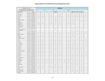
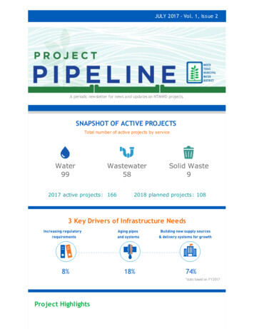
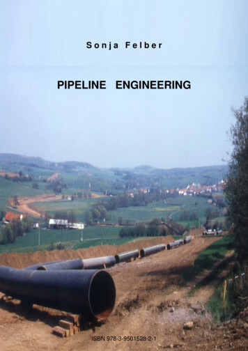
Fig. 1 Range extender configurations, allowing the monitoring of long pipeline sections with a single instrumentstimulated Brillouin scattering 关1兴. This scattering process is anintrinsic property of the propagation of light in the silica materialfrom which the sensing fiber is made. The Brillouin scatteringeffect exhibits a well-known and reproducible response to externalmeasurands such as temperature and strain.The Brillouin interaction results in the generation of scatteredlight, which experiences a frequency shift through the scatteringprocess. This frequency shift depends linearly on the fiber strainand temperature. As a consequence, the scattered light has aslightly different wavelength than the original light, and the departure from the original wavelength is directly dependent on thestrain and temperature of the fiber. A system based on the analysisof the Brillouin scattered light in optical fibers is naturally devotedto perform strain and temperature measurement.The main components of the DiTeSt system are the reading unitand the sensor cable. The reading unit is connected to the proximal end of the sensor and can be placed remotely from the sensingarea, since a section of optical fiber cable could be used to link thereading unit to the sensor itself without any performance degradation. The other sensor-end can be either connected to the sensortermination module 共single-end configuration兲, which could beplaced remotely from the sensor area as well, or brought back andconnected to the reading unit 共loop configuration兲. The selectionof the configuration 共single-end or loop兲 depends on the application. The use of optical amplifier modules 共range extenders兲 allows the monitoring of up to 300 km of pipeline from a singleinstrument 共see Fig. 1兲 关2兴. A scheme of the DiTeSt system isgiven in Fig. 2 and typical performances are given in Table 1.2.3 Sensing Cable Design. Traditional fiber optic cable design aims to give the best possible protection to the fiber itselffrom any external influence. In particular it is necessary to shieldthe optical fiber from external humidity, side pressures, and crushing and longitudinal strains applied to the cable. These designshave proven to be effective in guaranteeing the longevity of opti-cal fibers used for communication and can be used as sensingelements for monitoring temperatures in the 20 C to 60 Crange, in conjunction with Brillouin or Raman monitoringsystems.Sensing distributed temperature below 20 C or above 60 Crequires a specific cable design, especially for Brillouin scatteringsystems, where it is important to guarantee that the optical fiberdoes not experience any strain that could be misinterpreted as atemperature change due to the cross-sensitivity between strain andtemperature.On the other hand, the strain sensitivity of Brillouin scatteringprompts to the use of such systems for distributed strain sensing,in particular, to monitor local deformations of large structuressuch as pipelines, landslides, or dams. In these cases, the cablemust faithfully transfer the structural strain to the optical fiber, agoal contradicting all experiences from telecommunication cabledesign where the exact opposite is required.Finally, when sensing distributed strain it is necessary to simultaneously measure temperature to separate the two components.This is usually obtained by installing strain and temperature sensing cables in parallel. It would be therefore desirable to combinethe two functions into a single packaging.2.4 Extreme Temperature Sensing Cable. The extreme temperature sensing cables are designed for distributed temperaturemonitoring over long distances. They consist of up to four singlemode or multimode optical fibers contained in a stainless steelloose tube, protected with stainless steel armoring wires and optionally a polymer sheath. These components can be differentlycombined in order to adapt the cable to the required performanceand application. The use of appropriate optical fiber coating 共polyimide or carbon/polyimide兲 allows the operation over large temperature ranges; the stainless steel protection provides high mechanical and additional chemical resistance while the polymerFig. 2 Schema of DiTeSt system configurations, left: single-end configuration; right:loop configuration011701-2 / Vol. 132, FEBRUARY 2010Transactions of the ASME
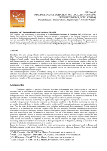
Table 1 Performances of DiTeSt systemMeasurement rangeNo. of channelsSpatial resolutionTemperature resolutionTemperature range 共dependson type of sensing cable兲Strain resolutionStrain range 共typical兲Acquisition time 共typical兲30 km 共standard兲150 km 共extended兲2 共standard兲max. 60 共with channel switch兲1 m over 5 km2 m over 25 km0.1 C 270 C to 500 C2 共0.002 mm/m兲 1.25 to 1.25%2 minsheath guarantees corrosion protection. The carbon coating offersimproved resistance to hydrogen darkening. The overlength of theoptical fibers is selected in such a way that the fiber is neverpulled or compressed, despite the difference in thermal expansioncoefficients between glass and steel. The total cable diameter isonly 3.8 mm 共see Fig. 3兲.These cables can be used in a wide range of applications thatrequire distributed temperature sensing, such as temperaturemonitoring of concrete in massive structures, waste disposal sites,onshore, off-shore and downhole sites in gas and oil industry, hotspots, cold spots, leakage detection of flow lines and reservoirs,fire detection in tunnels, and mapping of cryogenic temperatures,just to name a few.2.5 Strain Sensing Tape: SMARTape. When strain sensingis required, the optical fiber must be bonded to the host materialover the whole length 关3兴. The transfer of strain is to be complete,with no losses due to sliding. Therefore an excellent bonding between the strain optical fiber and the host structure is to be guaranteed. To allow such a good bonding, it has been recommendedto integrate the optical fiber within a tape in the similar manner asthe reinforcing fibers are integrated in composite materials. Toproduce such a tape, we selected a glass fiber reinforced thermoplastic with polyphenylene sulfide 共PPS兲 matrix. This material hasexcellent mechanical and chemical resistance properties. Since itsproduction involves heating to high temperatures 共in order to meltthe matrix of the composite material兲 it is necessary for the fiberto withstand this temperature without damage. In addition, thebonding between the optical fiber coating and the matrix has to beguaranteed. Polyimide-coated optical fibers fit these requirementsand were therefore selected for this design.The typical cross-sectional width of the thermoplastic composite tape that is used for manufacturing composite structures is inthe range of 10–20 mm and therefore not critical for optical fiberintegration. The thickness of the tape can be as low as 0.2 mm,and this dimension is more critical since the external diameter ofpolyimide-coated optical fiber is approximately 0.145 mm. Hence,Fig. 4 Cross section picture and micrograph of the sensingtape „SMARTape only less than 0.03 mm of the tape material remains on top orbottom of the optical fiber, with the risk that the optical fiber willemerge from the tape. The scheme of the sensing tape cross section, with typical dimensions, is presented in Fig. 4.The use of such sensing tape 共called SMARTape兲 is twofold: itcan be used externally, attached to the structure, or embeddedbetween the composite laminates, having also a structural role.2.6 Combined Strain and Temperature Sensing:SMARTprofile. The SMARTprofile sensor design combinesstrain and temperature sensors in a single package.This sensor consists of two bonded and two free single modeoptical fibers embedded in a polyethylene thermoplastic profile.The bonded fibers are used for strain monitoring, while the freefibers are used for temperature measurements and for compensating temperature effects on the bonded fibers. For redundancy, twofibers are included for both strain and temperature monitoring.The profile itself provides good mechanical, chemical, and temperature resistance. The size of the profile makes the sensor easyto transport and install by fusing, gluing, or clamping. TheSMARTprofile 共see Fig. 5兲 sensor is designed for use in environments often found in civil, geotechnical, and oil and gas applications. However, this sensor cannot be used in extreme temperatureenvironments or environments with high chemical pollution. It isnot recommended for installation under permanent UV radiation共e.g., sunshine兲.3Pipeline Monitoring ApplicationsIn Secs. 3.1–3.4 we will introduce application examples showing how different pipeline monitoring tasks can be addressed withthe presented system.Fig. 3 Extreme temperature sensing cable design andterminationJournal of Pressure Vessel Technology3.1 Leakage Detection in a Brine Pipeline. In 2002 the construction of a natural gas storage facility some 1500 m under theground surface was started in the area of Berlin in Germany. Using mining technology the building of underground caverns forgas storage in large rock-salt formation requires hot water andproduces large quantities of water saturated with salt, the so-calledbrine. In most cases the brine cannot be processed on-site andmust be transported by a pipeline to the location where it caneither be used for chemical processes, or injected back safely intothe ground. Because the brine can be harmful for the environment,the pipeline shall be monitored by a leakage detection system.In the Berlin project a 55 km pipeline was built and the company GESO was selected for the development and the installationFEBRUARY 2010, Vol. 132 / 011701-3
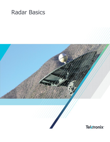
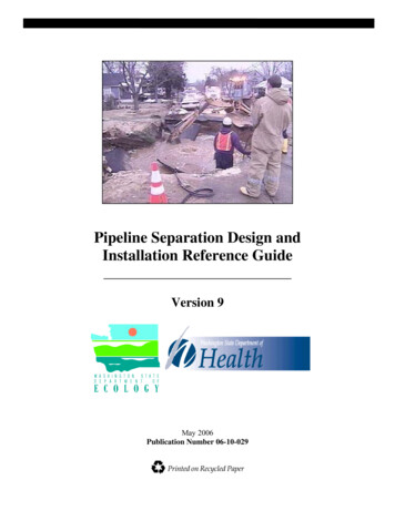
Fig. 5 SMARTprofile cross section and sample. The red tubecontains the free fibers.Fig. 6 Construction phase of a buried brine pipeline in thenorth-east area of Berlin. The fiber optics cable is placed in thesand at the 6 o’clock position about 10 cm underneath the pipeline †4‡.of the leakage detection system 关4兴. In order to cover the wholepipeline distance, it was decided to use two DiTeSt analyzers,although one instrument would have been theoretically able tocover the whole distance with its two channels. However the installation of the fiber cable required some 60 splices 共that correspond to an additional loss of up to 3 dB兲, which reduces thedistance range of the instrument accordingly and justifies the useof two instruments, since the range extender technology was notyet available.During the construction phase the temperature sensing was firstplaced in the trench and buried in the sand some 10 cm underneath the pipeline. The pictures in Fig. 6 show the construction ofthe pipeline before and after the pipeline was put in the trench.The temperature profiles measured by both DiTeSt instrumentsare transferred every 30 min to a central PC and further processedfor leakage detection. A dedicated software performs the leakagedetection through a comparison between recorded temperatureprofiles, looking at abnormal temperature evolutions and generating alarm in the case of the detection of a leakage. The system isable to automatically transmit alarms, to generate reports, to periodically reset and restart measurements, and requires virtually nomaintenance.The pipeline construction phase was completed in November2002, and the pipeline was put into operation in January 2003. InJuly 2003, a first leakage was detected by the monitoring system.It was later found that the leakage was accidentally caused byexcavation work in the vicinity of the pipeline. Figure 7 shows theoccurrence of the leakage and its effect on the temperature profilesshowing a local temperature increase of 8 C. An alarm was immediately and automatically triggered and the flow was eventuallystopped.3.2 Gas Pipeline Monitoring. About 500 m of a buried 35year old gas pipeline, located in Italy, lie in an unstable area.Distributed strain monitoring could be useful in order to improvevibrating wire strain gauges monitoring actually used in the site.The landslide progresses with time and could damage pipelines upto be put out of service. Three symmetrically disposed vibratingwires were installed in several sections at a distance of typically50/100 m chosen as the most stressed ones according to a preliminary engineering evaluation. These sensors were very helpful, butcould not fully cover the length of the pipeline and could onlyprovide local measurements.Fig. 7 Measured profiles before and after the leakage †3‡011701-4 / Vol. 132, FEBRUARY 2010Transactions of the ASME
Different types of distributed sensors were used: SMARTapeand temperature sensing cable. Three parallel lines, constituted offive segments of the SMARTape sensor, were installed over thewhole concerned length of the pipeline 共see Fig. 8兲. The lengths ofsegments ranged from 71 m to 132 m, and the position of thesensors with respect to the pipeline axis were at 0 deg, 120 deg,and 120 deg, approximately. The strain resolution of the SMARTape is 20 microstrains, with a spatial resolution of 1.5 m 共and anacquisition range of 0.25 m兲 and provides the monitoring of average strains, average curvatures, and deformed shape of the pipeline. The temperature sensing cable was installed on the upper line共0 deg兲 of the pipeline in order to compensate for the strain measurements for temperature. The temperature resolution of the sensor is 1 C with the same resolution and acquisition of the SMARTape. All the sensors are connected to a central measurement pointby means of extension optical cables and connection boxes. Theyare read from this point using a single DiTeSt reading unit. Sincethe landslide process is slow, the measurements sessions are performed manually once a month. In case of an earthquake a sessionof measurements is performed immediately after the event. All themeasurements obtained with the DiTeSt system are correlatedwith the measurements obtained with vibrating wires. At presentstage, the sensors have been measured for a period of 2 years,providing interesting information on the deformation induced byFig. 8 SMARTape on the gas pipelineMeasurements of sensors over all length of pipeline800SMARTape1]400Average strain 100150200250300350400450500Position [m]Fig. 9 Strain distribution over the monitored part of the pipeline measured by SMARTapesensorsSection strain and curvatures over all length of pipeline12502500Curvature 1000-2000-1250/m]]2000Average strain [Curvatrure XCurvature [Section ion [m]Fig. 10 Cross-sectional strain and curvature distributions measured by SMARTapesensorsJournal of Pressure Vessel TechnologyFEBRUARY 2010, Vol. 132 / 011701-5
Fig. 13 SmartPipe design, including SMARTprofile monitoringsystemFig. 11 Leakage simulation testburying and by the landslide progression. A gas leakage simulation was also performed with success using the temperature sensing cable.During the work, the pipe was laid on the soil supports every20–30 m. Therefore, its static system can be considered as a continuous girder. After the burring, the pipe was loaded with soil andtherefore deformed. The pipe cross sections located on the supports have been subject to negative bending 共traction at the toppart兲, and the section between the supports to positive bending共traction at the bottom part兲. The maximal allowed strain in theelastic domain is 1750 , and maximal curvature without normal forces 5303 / m. The diagram showing the strain distribution over the entire length of the pipeline after the burring mea-sured by SMARTapes is presented in Fig. 9. The normal crosssectional strain distribution and the curvature distribution in thehorizontal and vertical planes are calculated from the measurements and are presented in Fig. 10.During the placement of the sensors and the burring of the pipe,an empty plastic tube was installed connecting the upper part ofthe pipe with the surface, 50 m from the beginning of the firstmonitored segment. This tube was used to simulate a leakage ofthe gas. Carbon dioxide was inserted into the tube, cooling downthe pipe end due to pressure relaxation, and making the thermalconditions surrounding the contact between the pipe and the tubesimilar to conditions expected in case of leakage. This process ispresented in Fig. 11.A reference measurement was performed before the tube wascooled down. After the carbon dioxide was inserted, the temperature measurements were performed every 2–10 min and comparedwith the reference measurement. The results of the test are presented in Fig. 12. The test was successful and the point of simulated leakage was clearly observed in diagrams 共encircled area inFig. 12兲.Leakage simulation test1.00.5Temperature [ :15-3.00:30:470:44:58-3.5-4.020 25 30 35 40 45 50 55 60 65 70 75 80 85 90 95Position [m]Fig. 12 Results of leakage test; leakage is detected as temperature change011701-6 / Vol. 132, FEBRUARY 2010Transactions of the ASME
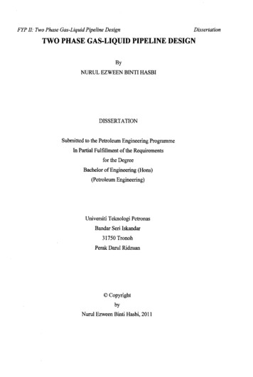
Fig. 14 SMARTprofile integration with high-strength fiberwindingsFig. 15 PDT-coil cross section. The fiber optics sensingSMARTprofiles are designated by SP-A, SP-B, and SP-C.3.3 Composite High-Pressure Pipe Monitoring: SmartPipe. Smart Pipe is a high-strength light weight monitored reinforced thermoplastic pipe that can be used for the rehabilitation ofan existing pipeline, or as a stand alone replacement. The keyfeature of the technology that underlies Smart Pipe is the use ofultrahigh-strength fibers that are wrapped onto a high densitypolyethylene core pipe 共see Fig. 13兲. Through the selection of thefibers, the lay angles, and their sizes, Smart Pipe can be speciallytailored for any given condition in terms of design pressure,pull-in length 共for a rehabilitation兲, and safe operating duration.In urban and environmentally sensitive areas, it delivers significant savings in the costs of access to and permitting for difficultlocations using its trenchless installation methods. It is simultaneously manufactured and installed as a tight fit liner in up to50,000 ft of an underground pipeline without any disruption of thesurface areas covering the pipeline 共except for a small opening atthe entry and exit points of the pipeline section being lined兲. It canrestore the subject pipeline to its full pressure service rating, renewing the projected service life of the subject pipeline to likenew or better than new condition, and in most cases does sowithout reducing the flow rates through the line despite the nominal reduction in the inside diameter of the pipeline that occurs dueto the presence of the liner.The integrated SMARTprofile sensors 共see Fig. 14兲 provide theoperator of the pipeline with continuous monitoring and inspec-tion features to assure safe operation of the line throughout therenewed operating life of the pipeline and to provide compliancewith the regulations now emerging under the various pipelinesafety acts.3.4 Composite Coiled Tubing Monitoring. The larger hydrocarbon reservoirs in Europe are rapidly depleting. The remaining marginal fields can only be exploited commercially by theimplementation of new “intelligent” technology such as electriccoiled tubing drilling or intelligent well completions. Steel CTwith an internal electric wire line is the current standard for suchoperations. Steel CT suffers from corrosion and fatigue problems,which dramatically restrict the operational life. The horizontalreach of steel CT is limited due to its heavy weight. The insertedwire line results in major hydraulic power losses and is cumbersome to install. To address these issues a joint research projectsupported by the European Commission was started in the year2000.The project aims to solve these problems by researching anddeveloping a high-temperature, corrosion, and fatigue resistantthermoplastic power and data transmission composite coiled tubing 共PDT-coil兲 for electric drilling applications. This PDT-coilcontains embedded electrical power and fiber optics for sensing,monitoring and data transmission.The PDT-coil consists of a functional liner containing the elec-Traction 0.25- Corrected - Relative1600140010 fibre1200m11b(strain) 0.2517 mm1000Strain [ με ]m11(strain) 0.255 fibrem13(0) 0.25Theor. 10Theor. 5800Theor. 10b11 mm600Theor. 5bTheor. 10(0)400Theor. 5(0)5 mm2000-20030405060708090Position [m]Fig. 16 Results of the traction test and comparison with theoretical predictionJournal of Pressure Vessel TechnologyFEBRUARY 2010, Vol. 132 / 011701-7
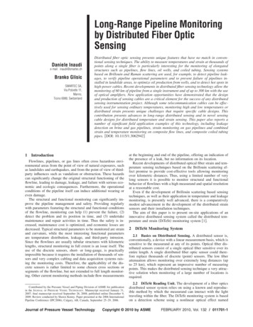
m07(twist) 0.25m09(0) 0.25Theorical 5Theorical -5Torsion 0.25 - Corrected - Relative1250Free 11000750Strain [ με ]500250m07b(twist) 0.25Theorical 10 Theorical -10 5 fibreFree 210 fibreFree 10-250-500-750-1000-125030405060708090Position [m]Fig. 17 Results of the torsion test and comparison with theoretical predictions; higher winding anglesprovide more sensitivity and accuracy for torsion measurementstrical and the optical conductors and a structural layer of carbonand glass fibers embedded in high performance thermoplasticpolymers. The electric conductors provide electric power for electric submersible pumps or electric drilling motors. A fiber opticsensing and monitoring system, based on the SMARTprofile design, is also integrated in the liner thickness over its whole lengthand is used to measure relevant well parameters and to monitorthe structural integrity of the PDT-coil, and can be used for datatransmission 共see Fig. 15兲.The embedded optical fiber system was tested for measuringstrain, deformations, and temperatures of the coil.Testing of distributed strain and deformation measurements wasperformed on a 15 m long section of polyethylene liner with integrated strain sensing fibers. The diameter of the tube was 56mm. Four optical fibers were installed with the angles of 2.5deg, 5 deg, 5 deg, and 10 deg with respect to the tube axis, inorder to evaluate the performance of fibers installed with differentangles. Two sensors with angles of 5 deg and 10 deg wereconnected one after the other, and a closed loop was created withthe reading unit. The temperature was measured on coils with freeoptical fibers installed before, between, and after the strain sensing sections.The aim of this test was to verify the performance of the monitoring system and algorithms. The following tests were performed: traction test, torsion test, combined traction and torsiontest, bending test, half tube bending test, double bending test, andcombined bending and torsion test.The results of this test confirmed the excellent performance ofthe DiTeSt reading unit, providing a resolution compatible withthe requirements 共better than 30 兲 and a short measurementtime 共better than 5 min兲. Resolution of temperature was betterthan 1 C. As examples, the results of traction and torsion tests arepresented in Figs. 16 and 17.To test the temperature sensing capabilities of the PDT-coilsensing system, a 150 m section of integrated liner was heated byinjecting different levels of current in the electrical conductors, asshown in Fig. 18.Figure 19 shows the recorded temperature profile for differentcurrent levels. It can be noticed that the temperature is not constant along the liner, since one part of the liner was in directcontact with the metallic winding drum that acted as a heat sink,while further sections were wound on a second layer that was011701-8 / Vol. 132, FEBRUARY 2010essentially surrounded by air and therefore thermally insulated. Inreal applications the PDT-coil tubing would be cooled by the fluids circulating inside and outside the pipe 关5兴.4ConclusionsThe use of distributed fiber optic monitoring system allowscontinuous monitoring and management of pipelines, increasingFig. 18 Liner heating test by electrical current inj
lows the monitoring of up to 300 km of pipeline from a single instrument see Fig. 1 2. A scheme of the DiTeSt system is given in Fig. 2 and typical performances are given in Table 1. 2.3 Sensing Cable Design. Traditional fiber optic cable de-sign aims to give the best possible protection to the fiber itself from any external influence.