Transcription
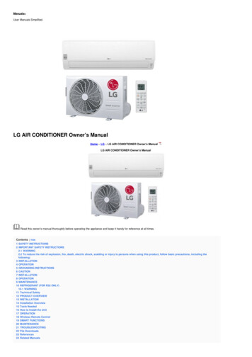
NORSKSUOMIOWNER’S MANUALDANSKAIRCONDITIONERPlease read this manual carefully before operatingyour set and retain it for future reference.TYPE : WINDOWMODELS LT0816CER LT1016CER LT1216CERP/NO : MFL69485301www.lg.com
Window-Type Air Conditioner Owner’s ManualTABLE OF CONTENTSSafety Precautions.3FOR YOUR RECORDSWrite the model and serial numbers here:Before Operation .7Model #Serial #Introduction .8You can find them on a label on the side of each unit.Dealer's NameSafety .9Date Purchased Staple your receipt to this page in the event you need itto prove date of purchase or for warranty issues.Installation .11Operating Instructions .18Maintenance and Service .21READ THIS MANUALInside you will find many helpful hints on how to use andmaintain your air conditioner properly. Just a little preventivecare on your part can save you a great deal of time andmoney over the life of your air conditioner.You'll find many answers to common problems in the chartof troubleshooting tips. If you review our chart ofTroubleshooting Tips first, you may not need to call forservice at all.PRECAUTION Contact the authorized service technician for repairor maintenance of this unit. Contact the installer for installation of this unit. The air conditioner is not intended for use by youngchildren or invalids without supervision. Young children should be supervised to ensure thatthey do not play with the air conditioner. When the power cord is to be replaced, replacementwork shall be performed by authorized personnel onlyusing only genuine replacement parts. Installation work must be performed in accordancewith the National Electric Code by qualified andauthorized personnel only.2 Room Air Conditioner
Safety PrecautionsSafety PrecautionsWARNINGThis symbol indicates the possibility of death or serious injury.CAUTIONThis symbol indicates the possibility of injury or damage to properties only.Meanings of symbols used in this manual are as shown below.Be sure not to do.Be sure to follow the instruction.WARNINGInstallationDon’t use a power cord, aplug, or a loose socketwhich is damaged. Otherwise, it may cause a fireor electrical shock.AlwaysAlways plugplug intointo aa groundedgroundedoutlet.outlet. Otherwise, it may cause a fireor electrical shock.DoDo notnot modifymodify oror extendextend thethepowerpower cordcord length.length. It will cause electric shock or firedue to heat generation.Do not disassemble ormodify products.Be caution when unpackingand installing.Do not store flammables likegasoline benzene, thinner, etc.near the air conditioner. It may cause failure andelectric shock. Sharp edges may causeinjury. It may cause explosion or fire.GasolinOwner’s Manual 3ENGLISHTo prevent injury to the user or other people and property damage, the following instructionsmust be followed.Incorrect operation due to ignoring instruction will cause harm or damage. The seriousnessis classified by the following indications.
Safety PrecautionsOperationDo not place heavy objecton the power cord and takecare so that the cord shouldnot be pressed.Do not share the outlet withother appliances. There is danger of fire or electricshock. It will cause electric shock or firedue to heat generation.Do not place the power cordnear a heater. It may cause fire and electricshock.Do not allow water to runinto electric parts. It will cause failure of machine orelectric shock.Take the power plug out ifnecessary, holding the headof the plug and do not touchit with wet hands. Otherwise, it may cause a fireor electrical shock.Use a soft cloth to clean. Donot use wax, thinner, or astrong detergent. The appearance of the airconditioner may deteriorate,change color, or develop surfaceflaws.xWa ThinnerUnplug the unit if strangesounds, odors, or smokecome from it.Do not open the suctioninlet grill of the productduring operation. Otherwise it may cause fire andelectric shock accident. Otherwise, it may electricalshock and failure.No correlation between fanusage and oxygen depletion.Turn off the power andbreaker first when cleansingthe unit. An oxygen shortage may occur. Since the fan rotates at highspeed during operation, it maycause injury.4 Room Air ConditionerIf water enters the product, turnoff the the power switch of themain body of appliance. Contactservice center after taking thepower-plug out from the socket.Unplug the unit when notusing it for a long time. Prevent accidental startup andthe possibility of injury.
Safety PrecautionsDo not operate or stop theunit by inserting or pullingout the power plug.Hold the plug by the headwhen taking it out. It may cause electric shock anddamage. It will cause electric shock or fire.When gas leaks, open thewindow for ventilationbefore operating the unit. Otherwise, it may causeexplosion, and a fire.Do not operate with wethands or in dampenvironment. It will cause electric shock.Never touch the metal partsof the unit when removingthe filter. They are sharp and may causeinjury.For inner cleaning, contact an Authorized Service Center or a dealer.Do not use harsh detergent that causes corrosion or damage on the unit.Harsh detergent may also cause failure of product, fire, or electric shock.CAUTIONInstallationInstall the product so the exhaust and noiseare not aimed directly at the neighbors. Be considerate.Follow installation instructions exactly. Otherwise, it may cause vibration or waterleakage.Owner’s Manual 5ENGLISH It will cause electric shock or firedue to heat generation.Do not damage or use anunspecified power cord.
Do not use this appliance forspecial purposes such ascooling pets, foods, precisionmachinery, or objects of art.Instead of running air conditioningconstantly,open a windowfor fresh air occasionally.You will feel better.If the liquid from the battery gets onto your skinor clothers,wash it well with clean water. Donot use the remote if the battery has leaked.yIf you eat the liquid from the battery,brushyour teeth and see doctor.Do not use theremote if the battery have leaked.y
2. No correlation between fan usage and oxygen depletion.3.7
IntroductionIntroductionSymbols Used in this ManualThis symbol alerts you to the risk of electric shock.This symbol alerts you to hazards that could cause harm tothe air conditioner.NOTICEThis symbol indicates special notes.FeaturesThis appliance should be installed in accordance with the National Electric Code.THE SLEEVE AND THE REAR GRILLE(optionally supplied with your unit)SLEEVE ASSEMBLY(Including Aluminum Rear grille)REAR GRILLE(Aluminum Rear grille)THE UNITVERTICAL AIR DEFLECTOR(Horizontal Louver)AIR DISCHARGEAIR FILTERCABINETINLET GRILLE(Air Intake)FRONT GRILLEHORIZONTAL AIR DEFLECTOR(Vertical Louver)VENT CONTROL8 Room Air Conditioner
RESETTESTbeshouldUSE OF EXTENSION CORDSRISK OF FIRE could cause serious injury or deathDO NOT use an extension cord with this windowair conditionerDO NOT use surge protectors or multi-outletadapters with this window air conditionerAvoid shock hazard. This unit cannotbe user-serviced. Do NOT open thetamper-resistant sealed portion.All warranties and performance willbe voided. This unit is not intendedto be used as an ON/OFF switch.
InstallationInstallationINSTALLATION REQUIREMENTSIf you use an existing wall sleeve, you shouldmeasure its dimensions.Install the new air conditioner according to theseinstallation instructions to achieve the bestperformance. All wall sleeves used to mount the newair conditioner must be in good structural conditionand have a rear grille to securely attach the new airconditioner. (Figure 1)With the LGE sleeve(optionally supplied withyour unit), you can maintain the best performance ofthe new air conditioner. (Figure 2)20-3/32"(511 mm)14-13/32"(366 mm)18-15/32"(468 mm)452 Size options896372 Size optionsNAME OF PARTSQ'TYPLASTIC GRILLE1VERTICAL INSULATION STRIP1AROUND INSULATION STRIPS2HORIZONTAL INSULATION STRIP1SUPPORT BLOCK2BAFFLE1TRIM FRAME2SHIM2PLASTIC NUTS AND WASHER SCREWS 4Figure 125-7/8"(656 mm)15-17/32"(394 mm)Aluminum metal grille16-23/32"(425 mm)LGE Wall Sleeve21ITEM12345678924"(610 mm)Air ConditionerINSTALLATION HARDWAREFigure 2ELECTRICAL SERVICECheck your available electrical service. The powersupply available must be the same as that shown onthe unit nameplate (found on left side of cabinet).All models are equipped with a 3-prong service plugto provide proper service and safe positivegrounding. Do not change plug in any way. Do notuse an adapter plug. If your present wall outlet doesnot match your plug, call a qualified electrician tomake the necessary corrections. SAVE CARTON forstorage and this OWNER'S MANUAL for futurereference. The carton is the best way to store unitduring winter or when not in use.To avoid risk of personal injury, propertydamage, or product damage due to the weight ofthis device and sharp edges that may beexposed: Air conditioners covered in this manual pose anexcessive weight hazard. Two or more people areneeded to move and install the unit.To prevent injury or strain, use proper lifting andcarrying techniques when moving unit. Carefully inspect location where air conditioner willbe installed. Be sure it will support the weight ofthe unit over an extended period of time. Handle air conditioner with care. Wear protectivegloves whenever lifting or carrying the unit. AVOIDthe sharp metal fins of front and rear coils. Make sure air conditioner does not fall duringinstallation.REQUIRED TOOLS: Tight Fitting gloves Standard screwdriver Phillips screwdriver Pliers Sharp knife 3/8-inch open endwrench or adjustablewrench 1/4-inch hex socketand ratchet Tape measure Electric drill 1/4-inch drill bitOwner’s Manual 11ENGLISHRemove packing materials from the wall sleeve and tapefrom the air conditioner.
InstallationINSTALLATIONNOTICEWe strongly recommend the removal of theold wall sleeve and the installation of a newLGE Wall Sleeve.If you decide to keep the existing wall sleeve,you have to redirect the louvers at the back ofthe wall sleeve illustration. The use of pliers isrecommended. If you DO NOT redirect, yourun the risk of poor performance or productfailure. This is not covered under the terms ofthe LGE warranty. Pick a location which will allow the conditioned airto blow into the area you want. Good installationwith special attention to the proper position of theunit will lessen the chance that service will beneeded.ITEMS IN INSTALLATION HARDWAREAll wall sleeves used to mount the new AirConditioner must be in sound structural conditionand have a rear grille that securely attaches tosleeve, or rear flange that serves as a stop for theAir Conditioner.2 Remove the old airconditioner from existing wallsleeve.3Clean the interior of the existing sleeve.(Do not disturb seals.)4Wall sleeve must be securely fastened in wallbefore installing the air conditioner. Use thenails or screws through sleeve into wall, ifneeded. Repaint sleeve if needed.5Prepare the wall sleeve for installation of theunit. If you plan to use your existing wall sleeve,and it is not LGE, use procedure B or C below.ProcedureAYou may not need all parts in the kit. Discard unusedparts.ITEM (inches)Qty.Plastic grille263/4 x 161/21Vertical insulation strip159/16 x 13/8 x 13/8 1671/8 x 13/8 x 25/32 1Around Insulation Strips5927/32 x 13/8 x 13/8 1Horizontal Insulation Strip 237/32 x 13/8 x 13/16 1Support Block13/4 x 13/8 x 45/162Baffle14 x 41/2 x 1/81Shim8 1/2 x 1 x 3/42Trim Frame2Washer Screw4Nuts (Plastic)4Grille Rear1HOW TO INSTALLIdentify the existing wall sleeve before installing1 theunit from the listed below.BrandWall Sleeve Dimensions re25-1/2Carrier (52F series)General son/FeddersCarrier (51S Series)Friedrich15-1/416, 17-1/2or 2215-5/816-7/8Depth(inches)16-23/3216, 17-1/2or 2216-7/817-1/8 or 2318-5/816-3/4or drichInstall new unit into wall sleeve.When installation is completed, the replacement unitMUST have a rearward slope as shown. Toachieve 1/4" slope, remove the backing from the8-1/2" shim strips and attach them as shownbelow in Fig. 3. Place the higher portion of the shim tothe front of the rib on the base of the wall sleeve.1" high3/4" HighUNIT17-1/8or 2316-3/42716-3/4or 19-3/425-7/8 15-17/32 16-23/3226-3/4 15-3/41525-3/4 tinghouseFrigidaire Carrier(52F series)General Electric/HotpointWhirlpoolCarrier (51S series)Wall Sleeve16-1/2FRONTShim6"6"SHIM PLACEMENT1/4"UNIT INSTALLATIONFigure 312 Room Air Conditioner
InstallationPROCEDURE A1Figure 42Fasten the 4 washer screws to secure the grilleto the wall sleeve. If you need plastic nuts tomount plastic grille to the inside of the wallsleeve, there are plastic nuts in the installationkit. The nuts are installed from the inside of thesleeve and are pressed into the square holesof the rear flanges.4Install the new unit into the wall sleeve.5To assemble trim, snap the tab of each pieceinto the slot of the other piece as shown below.Slide trim over the front of the air conditioneruntil trim is flush with sleeve as shown below.Trim (2 ea)WallFigure 7or3Figure 5Remove the backing from the vertical insulationstrip 15 9/16 x 13/8 x 13/8 and attach that to theinside right of the sleeve as shown below.Remove the backing from the around insulationstrip 671/8 x 13/8 x 25/32 and attach that to theinside front of the sleeve as shown below.IndoorOutdoorAround InsulationVertical Insulation9 1/2" Air conditioners covered in this manual pose anexcessive weight hazard. Two or more people areneeded to move and install the unit.To prevent injury or strain, use proper lifting andcarrying techniques when moving unit. When handling the air conditioner, be careful toavoid cuts from sharp metal fins on front and rearcoils. Make sure air conditioner does not fall duringremoval. If unit does not operate after installation check, tobe sure the circuit interrupter has not been tripped.Refer to the Troubleshooting guide for resetprocedure.6"Figure 6Owner’s Manual 13ENGLISHIf you are using the new sleeve (optionallysupplied with your unit), skip to step 3.Otherwise, install the plastic grille from the kit.Cut the plastic grille to 25-1/2" wide and 151/4" high. Place the plastic grille to the insideof the wall sleeve at the rear flange.
InstallationPROCEDURE B14Redirect the louvers at the back of the wallsleeve to 60 angle as shown in the Figure 8.The use of pliers is recommended.Remove the backing from the Vertical Insulationstrip 159/16 x 13/8 x 13/8 and attach that to theinside right of the sleeve as shown below.Remove the backing from the Around Insulationstrip 671/8 x 13/8 x 25/32 and attach that to theinside front of the sleeve as shown below.7 3/32"Indoor60 60 OutdoorRear LouversAround Insulation(Top View)Vertical InsulationFigure 82If the wall sleeve already has a rear grille, skipto step 4. If the wall sleeve does not have a reargrille or louvered panel, install the plastic grillefrom the kit. Cut the plastic grille to 25-1/2" wideand 15-1/4" high. Place the plastic grille to theinside of the wall sleeve at the rear flange.9 1/2"5If the depth of your existing wall sleeve is lessthan or equal to 18", skip to step 6. Otherwise,cut the baffles and the support blocks accordingto length A in the table below.Depth D of the existingwall sleeve (inches)1818-5/8D 18-5/8D 19-3/419-3/4 DPlace the plastic grille3Figure 9Fasten the 4 washer screws to secure the grilleto the wall sleeve. If you need plastic nuts tomount plastic grille to the inside of the wallsleeve, there are plastic nuts in the installationkit. The nuts are installed from the inside of thesleeve and are pressed into the square holes ofthe rear flanges.orFasten the screws14 Room Air ConditionerFigure 106"Figure 1122Length A(inches)ASupportBlock/431-3/44BaffleAFigure 12
InstallationPROCEDURE B6Remove the backing from the support blocksand attach them to the inside of the wall sleeveas shown in Figure 13. Slide the baffle intoslots of the support blocks.(7 3/32")WallWallSleeveBaffleFrontSupportBlockFigure 137Install the new unit into the wall sleeve.8Assemble trim as described in Step 5,Procedure A.CAUTION Air conditioners covered in this manual pose anexcessive weight hazard. Two or more people areneeded to move and install the unit.To prevent injury or strain, use proper lifting andcarrying techniques when moving unit. When handling the air conditioner, be careful toavoid cuts from sharp metal fins on front and rearcoils. Make sure air conditioner does not fall duringremoval. If unit does not operate after installation check, to besure the circuit interrupter has not been tripped.Refer to the Troubleshooting guide for resetprocedure.Owner’s Manual 15
InstallationPROCEDURE C14Redirect the louvers at the back of the wallsleeve to 60 angle as shown in the Figure 14.The use of pliers is recommended.7 3/32"Remove the backing from the horizontalinsulation strip 23 7/32 x 13/8 x 13/16 and attachthat to the inside right of the sleeve as shownbelow. Remove the backing from the aroundinsulation strip 59 27/32 x 13/8 x 13/8 and attachthat to the inside front of the sleeve as shownbelow.60 60 Rear LouversIndoorOutdoor(Top View)Around InsulationHorizontal InsulationFigue 142If the wall sleeve already has a rear grille, skipto step 4. If the wall sleeve does not have a reargrille or louvered panel, install the plastic grillefrom the kit. Cut the plastic grille to 26-1/2" wideand 15-1/2" high. Place the plastic grille to theinside of the wall sleeve at the rear flange.8 1/2"Figure 175If the depth of your existing sleeve is less thanor equal to 18”, skip to step 7. Otherwise, cutthe baffles and the support blocks according toLength A in the table below.Depth D of the existingwall sleeve (inches)1818-5/83Figure 15Fasten the 4 washer screws to secure the grilleto the wall sleeve. If you need plastic nuts tomount plastic grille to the inside of the wallsleeve, there are plastic nuts in the installationkit. The nuts are installed from the inside of thesleeve and are pressed into the square holes ofthe rear flanges.61-3/4D 19-3/4422BaffleAFigure 18Remove the backing from the support blocksand attach them to the inside of the wall sleeveas shown in Figure 19. Slide the baffle into slotsof the support blocks(7 3/32")WallBaffleFrontSupportBlockFigure 19or16 Room Air ConditionerSupportBlock3 4WallSleeveFasten the screwsA/D 18-5/819-3/4 DPlace the plastic grilleLength A(inches)Figure 16
Installation7To achieve rearward slope for unit draining,remove the backing from the 8 1/2 " shimstrips and attach them as shown below in Figure2 1. The higher portion of shim is to be placedin front of the rib on the base of wall sleeve.1" high3/4"HighFigure 20Shim (2EA)6"6"Figure 218Install the new unit into the wall sleeve.9Assemble trim as described in Step 6,Procedure A. Air conditioners covered in this manual pose anexcessive weight hazard. Two or more people areneeded to move and install the unit.To prevent injury or strain, use proper lifting andcarrying techniques when moving unit. When handling the air conditioner, be careful to avoidcuts from sharp metal fins on front and rear coils. Make sure air conditioner does not fall duringremoval. If unit does not operate after installation check, to besure the circuit interrupter has not been tripped.Refer to the Troubleshooting guide for resetprocedure.Owner’s Manual 17
Operating InstructionsOperating Instructions7REMOTE CONTROLLERTempFan SpeedTimerModePOWEROperation starts when this button is pressed and stops when youpress the button again.FAN SPEED SELECTORUse to set the fan speed to Low (F1), MED (F2), High (F3).ON/OFF TIMERDelay ON - when the air conditioner is off, it can be set to automatically turnon from 1 to 24 hours at its previous mode and fan settings.Delay OFF - when the air conditioner is on, it can be set to automatically turnoff from 1 to 24 hours.OPERATION MODE SELECTORPush the MODE button to rotate between Energy Saver / Cool / Fan / Dry.Energy Saver - The fan stops when the compressor stops cooling.Approximately every 3 minutes the fan will turn on and check the room airtemperature if cooling is needed.and FAN buttonsCool - Compressor runs and cools the room. Use theto set the desired temperature and circulation fan speed.Fan - Fan circulates air but compressor does not run. Use the FAN button to setthe desired fan speed.Dry - Dry mode is used to remove humidity from the room without additional cooling.Once the set temperature is reached,the compressor and circulation fan turns off.Fan speed is pre-set and cannot be adjusted.18 Room Air Conditioner
Operating InstructionsTEMPERATURE CONTROLREMOTE CONTROL SENSOR7 CLEAN FILTER‘Clean Filter’ LED will light up to notify you that your filter needs to be cleaned.After cleaning the filter, press “Temp” together to turn off ‘Clean Filter’ light.(Filter reset must be done from unit control panel not remote control).This feature is reminder to clean the Air Filter (See Maintenance) for more efficient operation.The LED (light) will illuminate after 250 hours of operation.During operation in failure of electric power, the unit runs as previous setting operation.ENERGY SAVERSAVERENERGYThe unit defaults to Energy Saver mode each time the unit is switched on exceptrestoration after an electrical power outage and fan mode.CAUTIONThe remote controller will not function properly if strong light strikes the sensor of the airconditioner or if there are obstacles between the remote controller and the air conditioner.y1. Push out the cover on the back of the remote control with your thumb.2. Pay attention to polarity and insert one new AAA 1.5V battery.3. Reattach the cover.Do not ure rechargeable battery. Make sure that the battery is new.Do not mix alkaline, standard (Carbon-zinc) or rechargeable (Nickel-cadmium)battery.- In order to prevent discharge, remove the batteries from the remote control ifthe air conditioner is not going to be used for an extended period of time.Keep the remote control away from extremely hot or humid places.To maintain optimal operation of the remote control, the remote sensor shouldnot be exposed to direct sunlight.Owner’s Manual 19ENGLISHThe thermostat monitors room temperature to maintain the desired temperature.The thermostat can be set between 60 F 86 F (16 C 30 C).
Operating InstructionsThe ventilation lever is located in the right of the air discharge.The ventilation lever must be in the CLOSEposotion in order to maintain the best cooling conditions. When fresh air is necessary in the room, setthe ventilation lever to the OPEN position. The damper is opened and room air is exhausted outside.The direction of air can be controlled wherever you want by adjusting the horizontal louver and the vertical louver. HORIZONTAL AIR-DIRECTION CONTROLThe horizontal air direction is adjusted by movingvertical louver.The lever of vertical louver is located in the right andleft side of the air discharge.20 Room Air Conditioner VERTICAL AIR-DIRECTION CONTROLThe vertical air direction is adjusted by movingthe horizontal louver.
Maintenance and ServiceMaintenance and ServiceAir Filter CleaningThe air filter should be checked at least twice a month to see if cleaning is necessary.Trapped particles in the filter will build up and block the airflow. This reduces the coolingcapacity and also causes an accumulation of frost on the cooling coils.If the filter becomes turn or damaged you should replaceimmediately. Replacement filters are available from yoursalesperson, dealer, and the authorized customer servicecenters.1. Open the inlet grille downward by pulling out the top of theinlet grille.2. Remove the air filter from the front grille assembly bypulling the air filter up slightly.3. Wash the filter using lukewarm water below 40 C (104 F).4. Gently shake the excess water from the filter completely.Replace the filter.How To Attach Front Grille To CabinentThe front grille can be removed for cleaning or to check the model and serial numbers.For your safety, you should attach the front grille as the following procedures.1. Pull down front grille from the cabinet top.2. Push front grille’s tips toward the cabinet inorder to insert front grille’s tabs into thecabinet.3. Open the inlet grille.4. Tighten the screw through the front grille intothe plate of control box.5. Close inlet grille.Guide the lever carefully through thegrille as you push it in.CoolF1 LOWF2 MEDF3 ROwner’s Manual 21ENGLISHTURN THE AIR CONDITIONER OFF AND REMOVE THE PLUG FROM THE POWER OUTLET.
call 1-800-243-0000.voltage and amperage.an outlet of the properWater drip from the rear of the unitNormal SoundHigh pitched ChatterToday’s high efficiency compressorsmay have a high pitched chatterduring the cooling cycle.Pinging or SwishingDroplets of water hittingcondenser during normaloperation may cause“pinging or swishing” sounds.Sound of Rushing AirAt the front of the unit, youmay hear the sound of rushingair being moved by the fan.Gurgle/Hiss“Gurgling or hissing” noise may beheard due to refrigerant passingthrough evaporator during normaloperation.22VibrationUnit may vibrate andmake noise because of poorwall or window constructionor incorrect installation.
The air conditioner isunplugged.The fuse is blown/circuitbreaker is tripped.Power failure.The current interrupterdevice is tripped.Air conditioner Airflow is restricted.does not coolas it shouldThe temp control may notbe set correctly.The air filter is dirty.The room may have beenhot.Cold air is escaping.Cooling coil have iced up.Air conditioner The cooling coils are icedover.freezing upWater dripsoutsideWater dripsindoorsHot, humid weather.ENGLISHAirconditionerdoes notstartMake sure the air conditioner plug is pushedcompletely into the outlet.Check the house fuse/circuit breaker box andreplace the fuse or reset the breaker.If power failure occurs, turn the mode controlto Off. When power is restored, wait 3 minutesto restart the air conditioner to prevent trippingof the compressor overload.Press the RESET button located on the powercord plug. If the RESET button will not stayengaged, discontinue use of the air conditionerand contact a qualified service technician.Make sure there are no curtains, blinds, orfurniture blocking the front of the air conditioner.In COOL model,press the DECREASE pad.Clean the filter at least every 2 weeks.See the care and Maintenance section.When the air conditioner is first turned on, youneed to allow time for the room to cool down.Check for open furnace floor registers and coldair returns.See Air Conditioner Freezing Up below.Ice may block the air flow and obstruct the airconditioner from properly cooling the room.Set the mode control at High Fan or High Cool.This is normal.For proper water disposal, make sure the airconditioner slants slightly from the case frontto the rear.Water collects Moisture removed from air This is normal for a short period in areas within base panand drains into base pan. little humidity; normal for a longer period invery humid areas.Air conditioner Dirty air filter - air restricted. Clean air filter.turns on and Outside temperatureSet FAN speed to a faster setting to bring airoff rapidly.extremely hot.through cooling coils more frequently.The air conditioner is nottilted to the outside.Air movement sound.Noise whenunit is cooling. Window vibration - poorinstallation.Remote control not locatedRemotewithin range.SensingDeactivating Remote control signalPrematurely. obstructed.Set temperature too lowRoom toocold.This is normal. If too loud, set to lower FAN setting.Refer to installation instructions or check withinstaller.Place remote control within 20 feet & 120 radiusof the front of the unit.Remove obstruction.lncrease set temperature.If you see “CH” in the display, please call 1-800-243-0000.3
Manual del usuario del acondicionador de aire tipo VentanaTABLA DE CONTENIDOSPARA SUS ARCHIVOSEscriba aquí el modelo y número de serie:Precauciones de Seguridad .25Antes de poner el equipo enfuncionamiento.29Modelo n :Serie n :Puede encontrar estos datos en la etiqueta situada en ellateral de cada unidad.Nombre del distribuidor:Fecha de compra:Introducción.30 Adjunte su recibo a esta página con la grapadora parael momento que lo necesite para probar la fecha de suadquisición o para la validación de la garantía.Seguraida.31Instalacion.33Instruccionnes deFuncionamiento.40Cuidado y Mantenimiento .43LEA ESTE MANUALEn su interior encontrará muchos consejos útiles sobre lautilización y mantenimiento de su acondicionador de aire.Unos pocos cuidados por su parte le pueden ahorrarmucho tiempo y dinero durante la vida de suacondicionador de aire.En la tabla de consejos para la solución rápida deproblemas encontrará muchas respuestas a los problemasmás habituales. Si revisa primero nuestra Tabla deConsejos para la solución rápida de problemas, tal vez nonecesite llamar nunca al servicio técnico.PRECAUCIÓN Póngase en contacto con un técnico del servicioautorizado para realizar la reparación ymantenimiento de esta unidad. Póngase en contacto con un instalador para realizarla instalación de esta unidad. Cuando se va a cambiar el cable eléctrico, el trabajode reemplazamiento debe ser realizado únicamentepor personal autorizado, utilizando las piezas decambio genuinas únicamente. El trabajo de reemplazamiento debe ser realizado deacuerdo con el Código Eléctrico
Owner's Manual 11 ENGLISH Installation Installation Remove packing materials from the wall sleeve and tape from the air conditioner. INSTALLATION REQUIREMENTS If you use an existing wall sleeve, you should measure its dimensions. Install the new air conditioner according to these installation instructions to achieve the best performance.