Transcription
A Leading Manufacturer of Quality Thermocouple and RTD Assemblies Since 1972 Address: W͘K͘ Ždž ϰϲϭϵϰϳ 'ĂƌůĂŶĚ͕ dy ϳϱϬϰϲ Phone: ϵϳϮͲϰϵϰͲϭϱϲϲ Toll Free: ϭͲϴϬϬͲϴϴϵͲϱϰϳϴ Website: ǁǁǁ͘ƚŚĞƌŵŽƐĞŶƐŽƌƐ͘ĐŽŵ Industrial ThermocouplesThermo Sensors Industrial thermocouples are widely used inprocess industry applications. Thermocouples are generallyselected by determining the particular conditions under which itmust perform. These conditions which have recommended wireand material selections and are grouped in types.Thermo Sensors thermocouple element types include:xxxxxxxxType E Chromel-Constantan ThermocoupleType J Iron-Constantan ThermocoupleType K Chromel-Alumel ThermocoupleType N Nicrosil-Nisil ThermocoupleType R Platinum-Platinum 13% Rhodium ThermocoupleType S Platinum-Platinum 10% Rhodium ThermocoupleType B Platinum 6% Rhodium-Platinum 30% Rhodium ThermocoupleType T Copper- Constantan ThermocoupleThe wire gauge and recommended temperature ranges are of various sizes as well.Please refer to our order guide to assist in determining your needs. We can also provide technical design assistance andapplication suggestions. Give us a call. dŚĞƌŵŽ ĞŶƐŽƌƐ ŽƌƉŽƌĂƚŝŽŶ ŽƉLJƌŝŐŚƚ ϮϬϭϯ ǁǁǁ͘ƚŚĞƌŵŽƐĞŶƐŽƌƐ͘ĐŽŵ WĂŐĞ ͮ ϭ
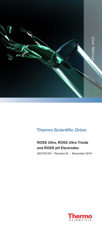
A Leading Manufacturer of Quality Thermocouple and RTD Assemblies Since 1972 Address: W͘K͘ Ždž ϰϲϭϵϰϳ 'ĂƌůĂŶĚ͕ dy ϳϱϬϰϲ Phone: ϵϳϮͲϰϵϰͲϭϱϲϲ Toll Free: ϭͲϴϬϬͲϴϴϵͲϱϰϳϴ Website: ǁǁǁ͘ƚŚĞƌŵŽƐĞŶƐŽƌƐ͘ĐŽŵ Introduction to ThermocouplesThe Principles and Features of ThermocouplesToday's thermocouple designs are the result of many years of research and fieldexperience. Together with quality instruments they provide the answer to thousandsof temperature sensing and control problems.The Seebeck EffectBasically, a thermocouple is a closed circuit formed of two dissimilar metallic conductors to produce an electromotive force(EMF) or voltage. The voltage causes a current to flow when heat is applied to one of the junctions. The current will continueto flow as long as the two junctions are at different temperatures. This is called the Seebeck effect, after T. J. Seebeck whodiscovered the principle.The direction of the current flow at the cooler of the two junctions (T1) determines polarity. For example, in Figure 2 whenthe current flows from A to B. a is considered positive.The Pettier EffectPeltier found that when current flows across the junction of two dissimilar metals the junction will either release heat orabsorb it, depending on the direction the current is flowing. If the current flows in the same direction as the current producedin a thermocouple at the measuring junction, heat will be absorbed and heat will be released at the opposing (cold) junction.The amount of heat absorbed and released is proportional to the quantity of electricity flowing across the junction.Thermoelectric LawsA. a circuit of a single homogeneous wire cannot maintain a current by means of heat application alone.B. In a circuit of two dissimilar homogeneous wires, if one junction is maintained at one temperature and the other junction atanother, the resulting thermal EMF will be independent of the temperature gradient along the wires.C. a third metal may be introduced into a circuit of two dissimilar homogeneous wires--with their measuring junction and coldjunction maintained at different temperatures - without affecting the total EMF (voltage) in the circuit. This law, often calledthe law of intermediate metals, works in the following manner: In a circuit of two dissimilar homogeneous wires A & B withmeasuring junction and cold junction maintained at different temperatures, introduce the third metal C by cutting the a wireand inserting wire C making two additional junctions a to C. If C is uniform in temperature over its entire length, the totaldŚĞƌŵŽ ĞŶƐŽƌƐ ŽƌƉŽƌĂƚŝŽŶ ŽƉLJƌŝŐŚƚ ϮϬϭϯ ǁǁǁ͘ƚŚĞƌŵŽƐĞŶƐŽƌƐ͘ĐŽŵ WĂŐĞ ͮ Ϯ
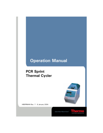
A Leading Manufacturer of Quality Thermocouple and RTD Assemblies Since 1972 Address: W͘K͘ Ždž ϰϲϭϵϰϳ 'ĂƌůĂŶĚ͕ dy ϳϱϬϰϲ Phone: ϵϳϮͲϰϵϰͲϭϱϲϲ Toll Free: ϭͲϴϬϬͲϴϴϵͲϱϰϳϴ Website: ǁǁǁ͘ƚŚĞƌŵŽƐĞŶƐŽƌƐ͘ĐŽŵ EMF in the circuit will be unaffected. This law can be applied, in various forms, to a thermocouple head where thethermocouple wires are connected to the extension wires through a copper or brass block.Common Thermocouple CircuitryBelow are examples of the most common thermocouple circuitry.1. Standard single thermocouple composed of two dissimilar wires and a single measuring junction:2. An averaging thermocouple composed two or more thermocouples connected in parallel to a common cold junction. TheEMF generated will correspond to the mean of the temperature of the individual junctions, provided resistances of all theelements are equal.3. a thermopile is composed of a series of two or more connected thermocouples. The resultant EMF will be the aggregateof all individual junctions.4. a Delta Thermocouple, also known as a differential thermocouple, is composed of two similar wires "A" joined to a singledissimilar wire "B" with the two measuring junctions normally at different temperatures. The resulting EMF will be thedifference between the two junctions, commonly referred to as the differential temperature.Note: At least one of the thermocouple junctions must be ungrounded and the measuring instrument must be of thedifferential type. a typical scale range might be: -150 to 0 to 150Purpose of Connection HeadsThe thermocouple connection or terminal head provides a positive electrical connection between the thermocouple andextension wires and provides a means of attachment for a protecting tube and extension wire conduit. The head contains aterminal block for all electrical connections. Connection heads are available for every application. Typical heads include acast aluminum cover head, ideal for applications which must be completely weatherproof; a polypropylene head for extremecorrosion areas, explosion-proof conduit type.dŚĞƌŵŽ ĞŶƐŽƌƐ ŽƌƉŽƌĂƚŝŽŶ ŽƉLJƌŝŐŚƚ ϮϬϭϯ ǁǁǁ͘ƚŚĞƌŵŽƐĞŶƐŽƌƐ͘ĐŽŵ WĂŐĞ ͮ ϯ
A Leading Manufacturer of Quality Thermocouple and RTD Assemblies Since 1972 Address: W͘K͘ Ždž ϰϲϭϵϰϳ 'ĂƌůĂŶĚ͕ dy ϳϱϬϰϲ Phone: ϵϳϮͲϰϵϰͲϭϱϲϲ Toll Free: ϭͲϴϬϬͲϴϴϵͲϱϰϳϴ Website: ǁǁǁ͘ƚŚĞƌŵŽƐĞŶƐŽƌƐ͘ĐŽŵ Extension Wire UseExtension wire is used to extend the thermocouple to the reference junction in the instrument. The wire is furnished as amatched pair of conductors with insulation designed to meet the service needs of a particular application. Application and Technical Data(See Section 100 "Cerampak Thermocouple" for Metal Sheathed Thermocouple Information)How to Select Thermocouple ElementsThe material selected for the thermocouple will be determined by the particular conditions under which it must perform.Suggested in this catalog are a series of element sizes and types of protections desirable under broad, general conditions.For maximum efficiency, however, the customer should carefully consider his particular needs and uses in terms of how longthe element must be in service, the temperatures to which it will be exposed, the atmosphere, and the desired speed ofresponse.Ranges of temperatures for the most commonly used thermocouple elements are shown in the Thermocouple SelectionData table. Where sensitivity for speed of response is important, select smaller gauge wires. Where longer life is a primaryconsideration, especially at elevated temperatures, select a heavier gauge wire.When ordering replacement thermocouple wire or elements be certain that the type (K, S, R, etc.) corresponds to theinstrument calibration for which it is intended. This information can usually be found on the face of the instrument.Following are type of elements available and descriptions of their general use:Table 1Thermocouple SelectionDataBare Wire - Ceramic InsulatorsType ofThermocouple orWire & MaterialRecommendedUpon TemperatureLimits FWireGauge(AWG) F CRecommended Conditions For UseType EChromel Constantan8 gauge14 gauge20 gauge24 gauge160012001005805870650540430Chromel-Constantan thermocouple suitable for use attemperatures up to 1600 F in vacuum, inert, mildly oxidizing orreducing atmospheres. Not subject to corrosion at cryogenictemperatures. Has highest EMF output per degree of all commonlyused thermocouples.Type JIron - Constantan8 gauge14 gauge20 gauge24 gauge14001100900700760590480370Used with or without protective tubing where deficiency of freeoxygen exists. Protective tube recommended but not essential,desirable for cleanliness and longer service. Since JP wire oxidizesrapidly above 1000 F, compensate by using larger gauge wires.dŚĞƌŵŽ ĞŶƐŽƌƐ ŽƌƉŽƌĂƚŝŽŶ ŽƉLJƌŝŐŚƚ ϮϬϭϯ ǁǁǁ͘ƚŚĞƌŵŽƐĞŶƐŽƌƐ͘ĐŽŵ WĂŐĞ ͮ ϰ
A Leading Manufacturer of Quality Thermocouple and RTD Assemblies Since 1972 Address: W͘K͘ Ždž ϰϲϭϵϰϳ 'ĂƌůĂŶĚ͕ dy ϳϱϬϰϲ Phone: ϵϳϮͲϰϵϰͲϭϱϲϲ Toll Free: ϭͲϴϬϬͲϴϴϵͲϱϰϳϴ Website: ǁǁǁ͘ƚŚĞƌŵŽƐĞŶƐŽƌƐ͘ĐŽŵ Maximum recommended operating temperature: 1400 F.Type KChromel - Alumel8 gauge14 gauge20 gauge24 gauge230020001800160012601080980820Type NNicrosil - Nisil8 gauge14 gauge20 gauge24 gauge230020001800160012601080980820Type RPlatinum - Platinum13% Rhodium24 gauge to 2700Type SPlatinum - Platinum10% Rhodium24 gauge to 2700Type BPlatinum 6%Rhodium - Platinum30% Rhodium24 gauge to 3150Type T14 gauge 700Copper - Constantan 20 gauge 50024 gauge 400Used extensively at temperatures up to 2300 F. Use of metal orceramic protective tube always recommended, especially inreducing atmospheres. In oxidizing atmospheres protective tubingnot essential, but desirable for longer service.For high temperature applications in oxidizing atmospheres, TypeB reduces effects of chemical contamination and rhodiummigration. It has greater mechanical strength than types S and R.Use a ceramic protection tube to obtain maximum reliability above1830 F in a neutral atmosphere, or air above 2190 F.370260204Use in either oxidizing or reducing atmospheres. Protection tubenot essential but recommended for cleanliness and longer service.Stable at lower temperatures. Superior for a wide variety of use inlow cryogenic temperatures. Operating range: - 300 F to 700 F,but can be used to - 425 F (boiling helium).Table 2 - Limit of ErrorReference Junction at 32 FThermocouple TemperatureCalibrationRangeLimits of ErrorStandard(Whichever is greater)Special(Whichever is greater)T-200 to 350 C-328 to 662 F 1 C 2 For 0.75% above O Cor 1.5 below O C .5 C 1 For .4%J0 to 750 C32 to 1382 F 2.2 C 4 For .75% 1.1 C 2 For .4%E-200 to 900 C-328 to 1652 F 1.7 C 3 For 0.5% above O Cor 1.0% below O C 1 C 2 For .4%K-200 to 1250 C 2.2 Cor 0.75% above O C 1.1 Cor .4%dŚĞƌŵŽ ĞŶƐŽƌƐ ŽƌƉŽƌĂƚŝŽŶ ŽƉLJƌŝŐŚƚ ϮϬϭϯ ǁǁǁ͘ƚŚĞƌŵŽƐĞŶƐŽƌƐ͘ĐŽŵ WĂŐĞ ͮ ϱ
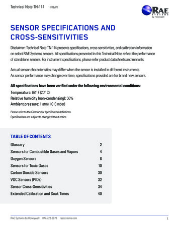
A Leading Manufacturer of Quality Thermocouple and RTD Assemblies Since 1972 R, SBN Address: W͘K͘ Ždž ϰϲϭϵϰϳ 'ĂƌůĂŶĚ͕ dy ϳϱϬϰϲ Phone: ϵϳϮͲϰϵϰͲϭϱϲϲ Toll Free: ϭͲϴϬϬͲϴϴϵͲϱϰϳϴ Website: ǁǁǁ͘ƚŚĞƌŵŽƐĞŶƐŽƌƐ͘ĐŽŵ -328 to 2282 F 4 For 2.0% below O C400 to 1400 C752 to 2550 C 1.5 C 3 For .25%or .1%or .50%or .25%800 to 1800 C 0.5%1475 to 3270 F over 800 C (1470 F)0 to 1250 C32 to 2282 F 2.2 C 4.0 For 0.75% above O Cor 2.0% below O C 2 F 1.1 C 2 For .4%When the limit of error is given in %, the percentage applies to the temperature being measured, not the range.Table 3 Temperature - Millivolt CurvesNote: EMF values for other calibrations available on request.dŚĞƌŵŽ ĞŶƐŽƌƐ ŽƌƉŽƌĂƚŝŽŶ ŽƉLJƌŝŐŚƚ ϮϬϭϯ ǁǁǁ͘ƚŚĞƌŵŽƐĞŶƐŽƌƐ͘ĐŽŵ WĂŐĞ ͮ ϲ
A Leading Manufacturer of Quality Thermocouple and RTD Assemblies Since 1972 Address: W͘K͘ Ždž ϰϲϭϵϰϳ 'ĂƌůĂŶĚ͕ dy ϳϱϬϰϲ Phone: ϵϳϮͲϰϵϰͲϭϱϲϲ Toll Free: ϭͲϴϬϬͲϴϴϵͲϱϰϳϴ Website: ǁǁǁ͘ƚŚĞƌŵŽƐĞŶƐŽƌƐ͘ĐŽŵ T/C Material TypesE CR/CN R Pt/Pt 13% RhJ I/CS Pt/Pt 10% RhB Pt 30% Rh/Pt 6% RhK C/AT CU/CN Installation and MaintenanceThermocouple Installation1.2.3.4.5.6.7.Carefully select the location and insertion depth at a point where the temperature is most likely representative ofthe process temperature. It is important to avoid stagnant areas of the measured media which do not haverepresentative temperatures.Locating the thermocouple where the hot end can be seen assures visual confirmation of the junction location.Immerse the thermocouple far enough to ensure that the measuring junction is entirely included in the temperaturearea to be measured. a depth ten times that of the diameter of the protection tube is recommended. Heat which isconducted away from the hot junction will cause a lower reading due to "stem loss."Keep the connecting head and cold junction in coolest ambient temperature available.To prevent breakage due to thermal shock, never insert a ceramic tube into a hot area rapidly. Preheat graduallywhile installing.Avoid direct flame impingement on protecting tube. Impingement shortens the tube life and causes temperaturereadings to be inaccurate.When measuring high temperatures, install the thermocouple vertically, whenever possible. Such installationminimizes sagging of the tube or sheath.Extension Wire Installation1.2.3.4.5.Be sure to select the correct type of extension wire for a given calibration of thermocouple. (See Bulletin 300).Use the color coding of individual wires as a guide for connecting the negative wire to the negative-wire terminal atboth the thermocouple connection head and the instrument. Red is always Negative (-).To prevent spurious EMF due to electrostatic and electromagnetic noise, never run thermocouple extension wire insame conduit, parallel to the conduit or near any power source. Keep thermocouple wire at least 12" from powersource.In "high noise" areas, use thermocouple extension wire with twisted and shielded conductors and a drainwire.Select the proper insulation to meet the specific conditions under which it must perform. (See Bulletin 300).General Maintenance1.2.3.4.5.6.Monthly maintenance checks are usually sufficient for base metal thermocouples. Individual conditions, however,may require more frequent checks.Keep rotary switches clean and free of oxidation at contact points.When reinserting a thermocouple, it is extremely important that the depth of insertion not be changed. Beespecially careful not to decrease the depth. Wires which are not homogeneous, due to exposure to the process,will cause errors in regions of temperature gradients.A type K thermocouple should not be exposed to temperatures of 1600 F or higher if it is to be used for accuratemeasurements below 1000 F.Do not use thermocouples with burned-out protecting tubes. Thermocouples can become damaged withcontamination if allowed to remain within tubes of poor condition.If thermocouples are to be connected in series, parallel or differential, refer to the diagrams on Page 3. dŚĞƌŵŽ ĞŶƐŽƌƐ ŽƌƉŽƌĂƚŝŽŶ ŽƉLJƌŝŐŚƚ ϮϬϭϯ ǁǁǁ͘ƚŚĞƌŵŽƐĞŶƐŽƌƐ͘ĐŽŵ WĂŐĞ ͮ ϳ
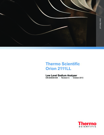
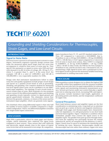
A Leading Manufacturer of Quality Thermocouple and RTD Assemblies Since 1972 Address: W͘K͘ Ždž ϰϲϭϵϰϳ 'ĂƌůĂŶĚ͕ dy ϳϱϬϰϲ Phone: ϵϳϮͲϰϵϰͲϭϱϲϲ Toll Free: ϭͲϴϬϬͲϴϴϵͲϱϰϳϴ Website: ǁǁǁ͘ƚŚĞƌŵŽƐĞŶƐŽƌƐ͘ĐŽŵ Terminal Head Connected Thermocouple AssembliesTable AFigure 1T/C Assembly with1/2" NPT Nipple/Union Extension(For Male Threaded Tubes and Wells)Figure 4Spring-Loaded T/CAssembly with 1/2" NPTPipe Nipple ExtensionFigure 2T/C Assembly with1/2" NPT Hex Fitting/Coupling/Nipple ExtensionFigure 5Spring-Loaded T/CAssembly with 1/2" NPTHex Fitting/UnionNipple ExtensionFigure 3Spring-Loaded T/CAssembly with 1/2" NPTHex FittingFigure 6Spring-Loaded T/CAssembly with 1/2" NPTNipple/Union/Nipple Extension* For custom extension length, add desired length as suffix to basic order code.Example: 5046, for 6" long extension.** Fitting/Extension shown in figures 2, 3, & 5 only available in stainless steel.dŚĞƌŵŽ ĞŶƐŽƌƐ ŽƌƉŽƌĂƚŝŽŶ ŽƉLJƌŝŐŚƚ ϮϬϭϯ ǁǁǁ͘ƚŚĞƌŵŽƐĞŶƐŽƌƐ͘ĐŽŵ WĂŐĞ ͮ ϴ
A Leading Manufacturer of Quality Thermocouple and RTD Assemblies Since 1972 Address: W͘K͘ Ždž ϰϲϭϵϰϳ 'ĂƌůĂŶĚ͕ dy ϳϱϬϰϲ Phone: ϵϳϮͲϰϵϰͲϭϱϲϲ Toll Free: ϭͲϴϬϬͲϴϴϵͲϱϰϳϴ Website: ǁǁǁ͘ƚŚĞƌŵŽƐĞŶƐŽƌƐ͘ĐŽŵ ***Hockey puck transmitter will fit these heads (see accessories section)****For corrosion resistance, epoxy coating can be ordered on these head options, Add "EC" as suffix to basic order code.Example: 300EC.- If connection head is not required, simply insert fiugre number as basic order code Example: 3How to Order:Tables A -B (Pages 6-8)Page 6- Page 7 -- TW SectionBasic Order CodeElement"L" LengthOrder Code for Thermowell104CU4K12If required (See Thermowell Section)Table ATable BTable CdŚĞƌŵŽ ĞŶƐŽƌƐ ŽƌƉŽƌĂƚŝŽŶ ŽƉLJƌŝŐŚƚ ϮϬϭϯ ǁǁǁ͘ƚŚĞƌŵŽƐĞŶƐŽƌƐ͘ĐŽŵ WĂŐĞ ͮ ϵ
A Leading Manufacturer of Quality Thermocouple and RTD Assemblies Since 1972 dŚĞƌŵŽ ĞŶƐŽƌƐ ŽƌƉŽƌĂƚŝŽŶ ŽƉLJƌŝŐŚƚ ϮϬϭϯ ǁǁǁ͘ƚŚĞƌŵŽƐĞŶƐŽƌƐ͘ĐŽŵ Address: W͘K͘ Ždž ϰϲϭϵϰϳ 'ĂƌůĂŶĚ͕ dy ϳϱϬϰϲ Phone: ϵϳϮͲϰϵϰͲϭϱϲϲ Toll Free: ϭͲϴϬϬͲϴϴϵͲϱϰϳϴ Website: ǁǁǁ͘ƚŚĞƌŵŽƐĞŶƐŽƌƐ͘ĐŽŵ WĂŐĞ ͮ ϭϬ
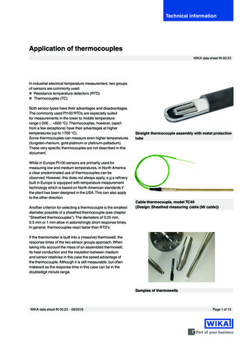
A Leading Manufacturer of Quality Thermocouple and RTD Assemblies Since 1972 Address: W͘K͘ Ždž ϰϲϭϵϰϳ 'ĂƌůĂŶĚ͕ dy ϳϱϬϰϲ Phone: ϵϳϮͲϰϵϰͲϭϱϲϲ Toll Free: ϭͲϴϬϬͲϴϴϵͲϱϰϳϴ Website: ǁǁǁ͘ƚŚĞƌŵŽƐĞŶƐŽƌƐ͘ĐŽŵ Single Thermocouple, 1/4" O.D. 316 S.S. Metal Sheathed ElementGrounded Hot Junction Ungrounded Hot JunctionTable BANSI CalibrationsOrdering CodeGrounded UngroundedJ - Iron - ConstantanC4JCU4JK - Chromel - AlumelC4KCU4KN - Nicrosil - NisilC4NCU4NT - Copper - ConstantanC4TCU4TE - Chromel - Constantan C4ECU4EDual Thermocouple 1/4" O.D. 316 S.S. Metal Sheathed ElementGrounded Hot Junction Ungrounded Hot Junction Ungrounded & Isolated (Remote) Hot JunctiondŚĞƌŵŽ ĞŶƐŽƌƐ ŽƌƉŽƌĂƚŝŽŶ ŽƉLJƌŝŐŚƚ ϮϬϭϯ ǁǁǁ͘ƚŚĞƌŵŽƐĞŶƐŽƌƐ͘ĐŽŵ WĂŐĞ ͮ ϭϭ
A Leading Manufacturer of Quality Thermocouple and RTD Assemblies Since 1972 Address: W͘K͘ Ždž ϰϲϭϵϰϳ 'ĂƌůĂŶĚ͕ dy ϳϱϬϰϲ Phone: ϵϳϮͲϰϵϰͲϭϱϲϲ Toll Free: ϭͲϴϬϬͲϴϴϵͲϱϰϳϴ Website: ǁǁǁ͘ƚŚĞƌŵŽƐĞŶƐŽƌƐ͘ĐŽŵ Table B continuedANSI CalibrationsOrdering CodeGrounded Ungrounded Ungrounded IsolatedJ - Iron - ConstantanD4JDU4JDUR4JK - Chromel - AlumelD4KDU4KDUR4KN - Nicrosil - NisilD4NDU4NDUR4NT - Copper - ConstantanD4TDU4TDUR4TE - Chromel - Constantan D4EDU4EDUR4E- Sheath materials other than 316 S.S. can be orderd by choosing a material code from the Material Table in Thermowellsection. Insert desired material code as suffix to order code. Example DU4K61.Tube Skin ThermocouplesMany types of tube skin thermocouples can be specified by using the tables on the preeding pages. Units with expansionloops and special mounting arrangements are illustrated below. Tube Skin/Furnace tube thermocouple configurations varywidely with individual customers. If you have designs other than shown below, please send us your specifications. We areexperienced in fabricating all designs currently used by most industries.DescriptionHead AssemblyCalibrationAs illustrated above with 1/4" Cerampak, 310 S.S. sheath, Groundedwelding pad 1 x 1 x 1/8" S.S.Furnished with one (1) hold down clamp.Expansion loops shop fabricated.Nipple Type (notshown)Chromel/Alumel TSA-K-(A)-(B)dŚĞƌŵŽ ĞŶƐŽƌƐ ŽƌƉŽƌĂƚŝŽŶ ŽƉLJƌŝŐŚƚ ϮϬϭϯ ǁǁǁ͘ƚŚĞƌŵŽƐĞŶƐŽƌƐ͘ĐŽŵ Order CodeIron/Constantan TSA-J-(A)-(B)Nipple-Union-Nipple Chromel/Alumel TSB-K-(A)-(B)TypeIron/Constantan TSB-J-(A)-(B)WĂŐĞ ͮ ϭϮ
A Leading Manufacturer of Quality Thermocouple and RTD Assemblies Since 1972 Address: W͘K͘ Ždž ϰϲϭϵϰϳ 'ĂƌůĂŶĚ͕ dy ϳϱϬϰϲ Phone: ϵϳϮͲϰϵϰͲϭϱϲϲ Toll Free: ϭͲϴϬϬͲϴϴϵͲϱϰϳϴ Website: ǁǁǁ͘ƚŚĞƌŵŽƐĞŶƐŽƌƐ͘ĐŽŵ How to Order:Specify "Order Code" deired and replace (A) & (B) with desired dimension in Inches.Example: TSA-K-40-16DescriptionHead AssemblyCalibrationOrder CodeAs illustrated above with 1/4" O.D. Cerampak, 310 S.S.sheath, Grounded welding pad 1 x 1 x 1/8" S.S.Furnished with one (1) hold down clamp."S" bends for expansion are formed by field personnel.Nipple TypeChromel/Alumel TSC-K-(Length)Iron/Constantan TSC-J-(Length)Nipple-Union-Nipple Type Chromel/Alumel TSD-K-(Length)(not shown)Iron/Constantan TSD-J-(Length)How to Order:Specify "Order Code" of assembly desired and replace (Length) with length desired in inches.Important: Length is measured from the bottom of the 1 1/2" NPT bushing to end of pad. Be sure to include sufficient lengthto field form the "S" bends.Example: TSD-K-120 dŚĞƌŵŽ ĞŶƐŽƌƐ ŽƌƉŽƌĂƚŝŽŶ ŽƉLJƌŝŐŚƚ ϮϬϭϯ ǁǁǁ͘ƚŚĞƌŵŽƐĞŶƐŽƌƐ͘ĐŽŵ WĂŐĞ ͮ ϭϯ
A Leading Manufacturer of Quality Thermocouple and RTD Assemblies Since 1972 Address: W͘K͘ Ždž ϰϲϭϵϰϳ 'ĂƌůĂŶĚ͕ dy ϳϱϬϰϲ Phone: ϵϳϮͲϰϵϰͲϭϱϲϲ Toll Free: ϭͲϴϬϬͲϴϴϵͲϱϰϳϴ Website: ǁǁǁ͘ƚŚĞƌŵŽƐĞŶƐŽƌƐ͘ĐŽŵ Metal Protecting Tube Assemblies - StraightCalibrationType JIron ConstantanElement* Tube *** Ordering CodeGaugeIPS O.D. Type MaterialAWG8 AWG14 AWGType KChromel Alumel8 AWG14 AWGType EChromel Constantan8 AWG14 AWGType NNicrosil - Nisil14 AWGOptionsHead"L"1/2" .840 JA12 Select Material Code from SelectSpecify in Adjustable Flange from table Inches3/4" 1.050 JA34 the Material Table in theIf Adjustable Flange is1" 1.315 JA10 Thermowell sectionbelowdesired, Add Suffix "-A" tocomplete Ordering Code.1/4" .540 JB14--------1/2" .840 JB12** Welded Bushing3/4" 1.050 JB34If a Welded Bushing is1" 1.315 JB10desired, Specify by AddingSuffix:1/2" .840 KA12-D(x) for 1/2 " NPT3/4" 1.050 KA34-F(x) for 3/4" NPT1" 1.315 KA10-H(x) for 1" NPT-K(x) for 1 1/4" NPT1/4" .540 KB14-M(x) for 1 1/2" NPT1/2" .840 KB12-P(x) for 2" NPT3/4" 1.050 KB34Replace the (x) with1" 1.315 KB10desired "X" dimension in1/2" .840 EA12inches.3/4" 1.050 EA34--------1" 1.315 EA10Welded FlangeIf a Welded Flange is1/4" .540 EB14desired, follow "L"1/2" .840 EB12dimension in Ordering3/4" 1.050 EB34Code with1" 1.315 EB10a) Flange Sizeb) Rating1/4" .540 NB14c) Facing1/2" .840 NB12d) Material3/4" 1.050 NB34e) "X" in Inches1" 1.315 NB10This Option is NotIllustrated.Other Calibrations and Tube Sizes are Available. Specify Your Requirements.* A single or dual element will be furnished according to the type of head selected from the table below.dŚĞƌŵŽ ĞŶƐŽƌƐ ŽƌƉŽƌĂƚŝŽŶ ŽƉLJƌŝŐŚƚ ϮϬϭϯ ǁǁǁ͘ƚŚĞƌŵŽƐĞŶƐŽƌƐ͘ĐŽŵ WĂŐĞ ͮ ϭϰ
A Leading Manufacturer of Quality Thermocouple and RTD Assemblies Since 1972 Address: W͘K͘ Ždž ϰϲϭϵϰϳ 'ĂƌůĂŶĚ͕ dy ϳϱϬϰϲ Phone: ϵϳϮͲϰϵϰͲϭϱϲϲ Toll Free: ϭͲϴϬϬͲϴϴϵͲϱϰϳϴ Website: ǁǁǁ͘ƚŚĞƌŵŽƐĞŶƐŽƌƐ͘ĐŽŵ Right Angle Assemblies - Pipe ExtendedCalibrationType JIron ConstantanElement*GaugeAWGTubeOrdering Code(Hot Leg)IPS O.D. Type Hot Leg** Material HeadColdLegHot Leg8 AWG1/2" .840 JA42 Select material code3/4" 1.050 JA64 from the Material1" 1.315 JA40 Table in theThermowell section1/2" .840 JB423/4" 1.050 JB641" 1.315 JB40SpecifyinInchesSpecifyinInches14 AWGType KChromel AlumelType EChromel Constantan8 AWG1/2" .840 KA423/4" 1.050 KA641" 1.315 KA4014 AWG1/2" .840 KB423/4" 1.050 KB641" 1.315 KB408 AWG1/2" .840 EA423/4" 1.050 EA641" 1.315 EA4014 AWG1/2" .840 EB423/4" 1.050 EB641" 1.315 EB40dŚĞƌŵŽ ĞŶƐŽƌƐ ŽƌƉŽƌĂƚŝŽŶ ŽƉLJƌŝŐŚƚ ϮϬϭϯ ǁǁǁ͘ƚŚĞƌŵŽƐĞŶƐŽƌƐ͘ĐŽŵ OptionsSelectfromtablebelowAdjustable Flange - Ifan adjustable flange isdesired, add suffix "A"to complete orderingcode.WĂŐĞ ͮ ϭϱ
A Leading Manufacturer of Quality Thermocouple and RTD Assemblies Since 1972 Type N8 AWGNicrosil - Nisil14 AWG Address: W͘K͘ Ždž ϰϲϭϵϰϳ 'ĂƌůĂŶĚ͕ dy ϳϱϬϰϲ Phone: ϵϳϮͲϰϵϰͲϭϱϲϲ Toll Free: ϭͲϴϬϬͲϴϴϵͲϱϰϳϴ Website: ǁǁǁ͘ƚŚĞƌŵŽƐĞŶƐŽƌƐ͘ĐŽŵ 1/2" .840 NA423/4" 1.050 NA641" 1.315 NA401/2" .840 NB423/4" 1.050 NB641" 1.315 NB40* a Single or dual element will be furnished according to the type of head selected from the table below.** All assemblies are supplies with standard hot legs made with schedule 40 pipes. To specify schedule 80 or 160 - insert"(80)" or "(160)" between the "Type" and "Material" selections in the ordering code table. Example: JA42(80)34-A-18-24.Exception: When a cast iron tube (material code 86 or 87) is used, pipe schedules do not apply. See page 41 fordimensions.Note: An ordering code type having a "64" in it (3/4" IPS) should be used when ordering an angle assembly with a cast irontube (material code 86 or 87).Terminal Head OptionsHeadTerminal Block SpecifyCast Iron Screw CoverSingleADualADCast Aluminum Screw Cover SingleBDualBDHow To Order:1.2.3.4.5.6.Select the type and gauge of element desired, the size of tube abailable from the first four columns of the table. Specifyby "Type" under ordering code.Select desired "Hot Leg" material code from the Material Table and add to "Type" designation.Select a head from table above and place its code letter next.Specify cold leg length in inches.Specify hot leg length in inches.Specify option next if desired.For Example:KA6436Type/Matl.-AHead- 18Cold LegdŚĞƌŵŽ ĞŶƐŽƌƐ ŽƌƉŽƌĂƚŝŽŶ ŽƉLJƌŝŐŚƚ ϮϬϭϯ ǁǁǁ͘ƚŚĞƌŵŽƐĞŶƐŽƌƐ͘ĐŽŵ - 24Hot Leg-AOptionWĂŐĞ ͮ ϭϲ
A Leading Manufacturer of Quality Thermocouple and RTD Assemblies Since 1972 Address: W͘K͘ Ždž ϰϲϭϵϰϳ 'ĂƌůĂŶĚ͕ dy ϳϱϬϰϲ Phone: ϵϳϮͲϰϵϰͲϭϱϲϲ Toll Free: ϭͲϴϬϬͲϴϴϵͲϱϰϳϴ Website: ǁǁǁ͘ƚŚĞƌŵŽƐĞŶƐŽƌƐ͘ĐŽŵ Right Angle Assemblies - 90 BendElement*GaugeAWGTubeOrdering Code(Hot Leg)IPS O.D. Type Hot Leg** Material HeadColdLegHot LegType JIron Constantan8 AWG1/2" .840 JA52 Select material code3/4" 1.050 JA74 from the MaterialTable in the1/2" .840 JB53Thermowell section3/4" 1.050 JB74SpecifyinInchesSpecifyinInchesType KChromel Alumel8 AWG1/2" .840 KA523/4" 1.050 KA7414 AWG1/2" .840 KB523/4" 1.050 KB74Type EChromel Constantan8 AWG1/2" .840 EA523/4" 1.050 EA7414 AWG1/2" .840 EB523/4" 1.050 EB74Calibration14 AWGType N8 AWGNicrosil - Nisil14 AWGOptionsSelectfromtablebelowAdjustable Flange - Ifan adjustable flange isdesired, add suffix "A"to complete orderingcode.1/2" .840 NA523/4" 1.050 NA741/2" .840 NB523/4" 1.050 NB74* a single or dual element will be furnished according to the type of head selected from the table below.** All assemblies are supplies with standard schedule 40 pipes. To specify schedule 80 or 160 - insert "(80)" or "(160)"between the "Type" and "Material" selections in the ordering code table. Example: JA52(80)36-A- 24-36 for a schedule 80pipe.dŚĞƌŵŽ ĞŶƐŽƌƐ ŽƌƉŽƌĂƚŝŽŶ ŽƉLJƌŝŐŚƚ ϮϬϭϯ ǁǁǁ͘ƚŚĞƌŵŽƐĞŶƐŽƌƐ͘ĐŽŵ WĂŐĞ ͮ ϭϳ
A Leading Manufacturer of Quality Thermocouple and RTD Assemblies Since 1972 Address: W͘K͘ Ždž ϰϲϭϵϰϳ 'ĂƌůĂŶĚ͕ dy ϳϱϬϰϲ Phone: ϵϳϮͲϰϵϰͲϭϱϲϲ Toll Free: ϭͲϴϬϬͲϴϴϵͲϱϰϳϴ Website: ǁǁǁ͘ƚŚĞƌŵŽƐĞŶƐŽƌƐ͘ĐŽŵ Terminal Head OptionsHeadTerminal Block SpecifyCast Iron Screw CoverSingleADualADCast Aluminum Screw Cover SingleBDualBDHow to order:1.2.3.4.5.6.Select the type and gauge of element desired, the size of tube abailable from the first four columns of the table. Specifyby "Type" under ordering code.Select desired tube material code from the Material Table and add to "Type" designation.Select a head from table above and place its code letter next.Specify cold leg length in inches.Specify hot leg length in inches.Specify option next if desired.For Example:KA748Type/Matl.-AHead- 18Cold Leg- 24Hot Leg-AOptionCeramic Protecting Tube CharacteristicsThermo Sensors Corporation ceramic tubes are high quality, fine grained, * non-porous tubes. They are impervious to gasesat temperatures near their melting point. Materials available range from mullite (C3 Ceramic) to high purity alumina (C98Ceramic). Material selection depends upon operating conditions and performance requirements such as temperature,atmosphere, sensitivity to contamination and others. Ͳ ȋ ȌMaximum operating temperature of 2900 F (1600 C). Impervious to air to 3000 F, to dry hydrogen and carbon monoxideto 2550 F. Low rate of thermal expansion (2.8 x 10⁻⁶/ F) enhances thermal shock resistance. Resistance to acid slag isgood. Basic slag is fair. Recommended for J, K, N, and E type thermocouples. ͻͺ ȋͻͻǤͺΨ ȌMaximum operating temperature 3450 F (1900 C) in both oxidizing and reducing atmospheres. Inert to hydrogen, carbon,platinum, rhodium and refractory metals under most conditions. High thermal conductivity for fast temperature response.Being more dense than C30, affords longer life in acids, alkalis, molten metals, molten salts and slags. Impervious to mostindustrial furnace gases even at high temperatures. Recommended for R, S and B type thermocouples.dŚĞƌŵŽ ĞŶƐŽƌƐ ŽƌƉŽƌĂƚŝŽŶ ŽƉLJƌŝŐŚƚ ϮϬϭϯ ǁǁǁ͘ƚŚĞƌŵŽƐĞŶƐŽƌƐ͘ĐŽŵ WĂŐĞ ͮ ϭϴ
A Leading Manufacturer of Quality Thermocouple and RTD Assemblies Since 1972 Ǧ ȋ ǦͳȌ Address: W͘K͘ Ždž ϰϲϭϵϰϳ 'ĂƌůĂŶĚ͕ dy ϳϱϬϰϲ Phone: ϵϳϮͲϰϵϰͲϭϱϲϲ Toll Free: ϭͲϴϬϬͲϴϴϵͲϱϰϳϴ Website: ǁǁǁ͘ƚŚĞƌŵŽƐĞŶƐŽƌƐ͘ĐŽŵ Maximum operating temperature of 2800 F (1538 C). This tube is a combination of aluminum oxide and chromium. Stablein oxidizing atmospheres to 2200 F. Thermal and mechanical shock characteristics are better than pure ceramic tubes, butan extreme temperature span requires a slow insertion time to allow tube to preheat. Sulphur dioxide, sulphur trioxide andconcentrated sulphuric acids have little effect on MCT tubes. Since copper, zinc, lead, brass and ferrous alloys do not "wet"MCT tubes their life is longer in such melts, abrasive resistance even at 2200 F. Do not use in acid or carbide slags ormolten aluminum. ȋ ȌMaximum operating temperature of 3000 F (1649 C). Suggested as primary tube in molten aluminum. Porous* and affordsprotection from flame cutting. a secondary tube to provide thermal and mechanical shock resistance in assemblies usingC30 and C98 as a primary. dŚĞƌŵŽ ĞŶƐŽƌƐ ŽƌƉŽƌĂƚŝŽŶ ŽƉLJƌŝŐŚƚ ϮϬϭϯ ǁǁǁ͘ƚŚĞƌŵŽƐĞŶƐŽƌƐ͘ĐŽŵ WĂŐĞ ͮ ϭϵ
A Leading Manufacturer of Quality Thermocouple and RTD Assemblies Since 1972 Address: W͘K͘ Ždž ϰϲϭϵϰϳ 'ĂƌůĂŶĚ͕ dy ϳϱϬϰϲ Phone: ϵϳϮͲϰϵϰͲϭϱϲϲ Toll Free: ϭͲϴϬϬͲϴϴϵͲϱϰϳϴ Website: ǁǁǁ͘ƚŚĞƌŵŽƐĞŶƐŽƌƐ͘ĐŽŵ Ceramic Protecting Tube Assembly - StraightCalibration Element Tube ***MaterialGauge(AWG.)NPT***I.D. xO.D.TypeHead"L"Type N8 AWG.Nicrosil - NisilC30 CeramicC98 Ceramic9/16" x NA303/4"NA9814 AWG. C30 CeramicC98 Ceramic7/16" x NB3011/16" NB98SelectHeadFromTableBelow8 AWG.C30 CeramicC98 Ceramic
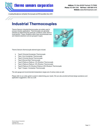
Thermo Sensors Industrial thermocouples are widely used in process industry applications. Thermocouples are generally selected by determining the particular conditions under which it must perform. These conditions which have recommended wire and material selections and are grouped in types. Thermo Sensors thermocouple element types include: