Transcription
eBook:Introduction toKubernetes Networkingand SecurityA step-by-step guide covering everything you need to know to confidentlyapproach Kubernetes networking, starting with basic networking concepts,all the way through to advanced Kubernetes networking with eBPF.
Table of ContentsIntroduction . . . . . . . . . . . . . . . . . . . . . . . . . . . . . . . . . . . . . . . . . . . . . . . . . . . . . . . . . . . . . . . . . . . . . . . . . . . . . . . . . . . 51. Networking . . . . . . . . . . . . . . . . . . . . . . . . . . . . . . . . . . . . . . . . . . . . . . . . . . . . . . . . . . . . . . . . . . . . . . . . . . . . . . . . . . 6Network layersAnatomy of a network packetIP addressing, subnets and IP routingOverlay networksDNSNATMTU6778910102. Kubernetes Networking . . . . . . . . . . . . . . . . . . . . . . . . . . . . . . . . . . . . . . . . . . . . . . . . . . . . . . . . . . . . . . . . . . 1 1The Kubernetes network modelKubernetes network implementationsKubernetes ServicesKubernetes DNSNAT outgoingDual stackAbove and beyond111112121313133. Network Policy . . . . . . . . . . . . . . . . . . . . . . . . . . . . . . . . . . . . . . . . . . . . . . . . . . . . . . . . . . . . . . . . . . . . . . . . . . . . . 14What is network policy?Why is network policy important?Kubernetes network policyCalico network policyBenefits of using Calico for network policyFull Kubernetes network policy supportRicher network policyMix Kubernetes and Calico network policyAbility to protect hosts and VMsIntegrates with IstioExtendable with Calico EnterpriseBest practices for network policiesIngress and egressPolicy schemasDefault denyHierarchical policy141415161616161617171718181819192
4. Kubernetes Services . . . . . . . . . . . . . . . . . . . . . . . . . . . . . . . . . . . . . . . . . . . . . . . . . . . . . . . . . . . . . . . . . . . . . 20What are Kubernetes Services?Cluster IP servicesNode port servicesLoad balancer servicesAdvertising service IPsexternalTrafficPolicy:localCalico eBPF native service handlingAbove and beyond20212122232324245. Kubernetes Ingress . . . . . . . . . . . . . . . . . . . . . . . . . . . . . . . . . . . . . . . . . . . . . . . . . . . . . . . . . . . . . . . . . . . . . . 25What is Kubernetes Ingress?Why use Kubernetes Ingress?Types of Ingress solutionsIn-cluster ingress solutionsExternal ingress solutionsShow me everything!Above and beyond252526262627296. Kubernetes Egress . . . . . . . . . . . . . . . . . . . . . . . . . . . . . . . . . . . . . . . . . . . . . . . . . . . . . . . . . . . . . . . . . . . . . . . 30What is Kubernetes Egress?Restricting egress trafficNAT outgoingEgress gatewaysAbove and beyond30303131327. eBPF . . . . . . . . . . . . . . . . . . . . . . . . . . . . . . . . . . . . . . . . . . . . . . . . . . . . . . . . . . . . . . . . . . . . . . . . . . . . . . . . . . . . . . . . . 33What is eBPF?Why is it called eBPF?What can eBPF do?Types of eBPF programBPF mapsCalico’s eBPF dataplaneFeature comparisonArchitecture overviewAbove and beyond333333333434353637Table of Contents 3
8. Calico . . . . . . . . . . . . . . . . . . . . . . . . . . . . . . . . . . . . . . . . . . . . . . . . . . . . . . . . . . . . . . . . . . . . . . . . . . . . . . . . . . . . . . . 38What is Calico?Why use Calico?Choice of dataplanesBest practices for network securityPerformanceScalabilityInteroperabilityReal world production hardenedFull Kubernetes network policy supportContributor communityCalico Enterprise compatible38383839393940404041419. Calico Enterprise . . . . . . . . . . . . . . . . . . . . . . . . . . . . . . . . . . . . . . . . . . . . . . . . . . . . . . . . . . . . . . . . . . . . . . . . . . 42What is Calico Enterprise?Pilot, pre-productionEgress access controlsVisibility, traceability, troubleshootingSecurity controls for segmentationProduction, initial appsSelf-service with control and compliancePolicy lifecycle and automationExtend firewalls to KubernetesProduction, mass migrationThreat defense and anomaly detectionSingle management plane and federationProtect non-cluster hosts with policyComplianceZero trust network security modelRoadmap to production with s and Getting Started . . . . . . . . . . . . . . . . . . . . . . . . . . . . . . . . . . . . . . . . . . . . . . . . . . . . . . . . . . . 51Table of Contents 4
IntroductionKubernetes has become the de facto standard for managingcontainerized workloads and services. By facilitating declarativeconfiguration and automation, it massively simplifies the operationalcomplexities of reliably orchestrating compute, storage, andnetworking. The Kubernetes networking model is a core enabler ofthat simplification, defining a common set of behaviors that makescommunication between microservices easy and portable across anyenvironment.This guide arms the reader with the knowledge they need to understand the essentials of how Kubernetes networkingworks, how it helps simplify communication between microservices, and how to secure your cluster networkingfollowing today’s best practices.Starting from an introduction to basic networking concepts, the book builds knowledge in easily digestible incrementsacross the breadth of Kubernetes networking, leading up to some of the latest advances in networking extensions andimplementations.About the Author:Alex PollittAlex Pollitt, is CTO and co-founder of Tigera, the team that created Project Calico, the leading opensource networking and network security solution for Kubernetes. With a background in developingcarrier grade networking software, he was an early contributor to the Kubernetes community andhelped influence early Kubernetes networking ideas that are today taken for granted.Twitter: @lxpollitt.NEW Free Calico Certification!Become a Kubernetes networking and network security expert.Learn More5
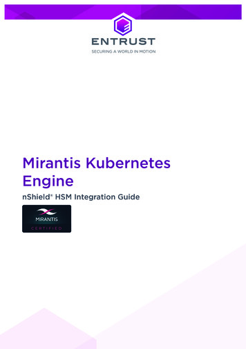
Chapter 1NetworkingYou can get up and running with Calico by following any of the Calico install guides without needing to be anetworking expert. Calico hides the complexities for you. However, if you would like to learn more about networking soyou can better understand what is happening under the covers, this guide provides a short introduction to some of thekey fundamental networking concepts for anyone who is not already familiar with them.In this chapter you will learn: The terms used to described different layers of the network. The anatomy of a network packet. What MTU is and why it makes a difference. How IP addressing, subnets, and IP routing works. What an overlay network is. What DNS and NAT are.Network layersThe process of sending and receiving data overa network is commonly categorized into 7 layers(referred to as the OSI model ). They layers are typicallyabbreviated as L1 - L7. You can think of data as passingthrough each of these layers in turn as it is sent orreceived from an application, which each layer beingresponsible for a particular part of the processingrequired to send the data over the network.In a modern enterprise or public cloud network, the layerscommonly map as follows: L5-7: all the protocols most application developersare familiar with. e.g. HTTP, FTP, SSH, SSL, DNS. L4: TCP or UDP, including source and destinationports. L3: IP packets and IP routing. L2: Ethernet packets and Ethernet switching.6
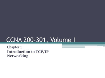
Anatomy of a network packetWhen sending data over the network, each layer in the network stack adds its own header containing the control/metadata the layer needs in order to process the packet as it traverses the network, passing the resulting packet onto the next layer of the stack. In this way the complete packet is produced, which includes all the control/metadatarequired by every layer of the stack, without any layer understanding the data or needing to process the control/metadata of adjacent network layers.IP addressing, subnets and IP routingThe L3 network layer introduces IP addresses and typically marks the boundary between the part of networkingthat application developers care about, and the part of networking that network engineers care about. In particularapplication developers typically regard IP addresses as the source and destination of the network traffic, but havemuch less of a need to understand L3 routing or anything lower in the network stack, which is more the domain ofnetwork engineers.There are two variants of IP addresses: IPv4 and IPv6. IPv4 addresses are 32 bits long and the most commonly used. They are typically represented as 4 bytes indecimal (each 0-255) separated by dots. e.g. 192.168.27.64 . There are several ranges of IP addresses that arereserved as “private”, that can only be used within local private networks, are not routable across the internet.These can be reused by enterprises as often as they want to. In contrast “public” IP addresses are globally uniqueacross the whole of the internet. As the number of network devices and networks connected to the internet hasgrown, public IPv4 addresses are now in short supply.Chapter 1 : Networking 7
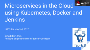
IPv6 addresses are 128 bits long and designed to overcome the shortage of IPv4 address space. They are typicallyrepresented by 8 groups of 4 digit hexadecimal numbers. e.g. 1203:8fe0:fe80:b897:8990:8a7c:99bf:323d .Due to the 128 bit length, there’s no shortage of IPv6 addresses. However, many enterprises have been slow toadopt IPv6, so for now at least, IPv4 remains the default for many enterprise and data center networks.Groups of IP addresses are typically represented using CIDR notation that consists of an IP address and number ofsignificant bits on the IP address separated by a / . For example, 192.168.27.0/24 represents the group of 256 IPaddresses from 192.168.27.0 to 192.168.27.255 .A group of IP addresses within a single L2 network is referred to as a subnet. Within a subnet, packets can be sentbetween any pair of devices as a single network hop, based solely on the L2 header (and footer).To send packets beyond a single subnet requires L3 routing, with each L3 network device (router) being responsiblefor making decisions on the path to send the packet based on L3 routing rules. Each network device acting as arouter has routes that determine where a packet for a particular CIDR should be sent next. So for example, in a Linuxsystem, a route of 10.48.0.128/26 via 10.0.0.12 dev eth0 indicates that packets with destination IP address in10.48.0.128/26 should be routed to a next network hop of 10.0.0.12 over the eth0 interface.Routes can be configured statically by an administrator, or programmed dynamically using routing protocols. Whenusing routing protocols each network device typically needs to be configured to tell it which other network devices itshould be exchanging routes with. The routing protocol then handles programming the right routes across the wholeof the network as devices are added or removed, or network links come in or out of service.One common routing protocol used in large enterprise and data center networks is BGP. BGP is one of the mainprotocols that powers the internet, so scales incredibly well, and is very widely supported by modern routers.Overlay networksAn overlay network allows network devices to communicate across an underlying network (referred to as theunderlay) without the underlay network having any knowledge of the devices connected to the overlay network. Fromthe point of view of the devices connected to the overlay network, it looks just like a normal network. There are manydifferent kinds of overlay networks that use different protocols to make this happen, but in general they share thesame common characteristic of taking a network packet, referred to as the inner packet, and encapsulating it insidean outer network packet. In this way the underlay sees the outer packets without needing to understand how to handlethe inner packets.How the overlay knows where to send packets varies by overlay type and the protocols they use. Similarly exactly howthe packet is wrapped varies between different overlay types. In the case of VXLAN for example, the inner packet iswrapped and sent as UDP in the outer packet.Chapter 1 : Networking 8
Overlay networks have the advantage of having minimal dependencies on the underlying network infrastructure, buthave the downsides of: having a small performance impact compared to non-overlay networking, which you might want to avoid ifrunning network intensive workloads workloads on the overlay are not easily addressable from the rest of the network. so NAT gateways or loadbalancers are required to bridge between the overlay and the underlay network for any ingress to, or egress from,the overlay.Calico networking options are exceptionally flexible, so in general you can choose whether you prefer Calico to providean overlay network, or non-overlay network. You can read more about this in the Calico determine best networkingoption guide.DNSWhile the underlying network packet flow across a the network is determined using IP addresses, users andapplications typically want to use well known names to identify network destinations that remain consistent over time,even if the underlying IP addresses change. For example, to map google.com to 216.58.210.46 . This translationfrom name to IP address is handled by DNS. DNS runs on top of the base networking described so far. Each deviceconnected to a network is typically configured with the IP addresses one or more DNS servers. When an applicationwants to connect to a domain name, a DNS message is sent to the DNS server, which then responds with informationabout which IP address(es) the domain name maps to. The application can then initiate its connection to the chosenIP address.Chapter 1 : Networking 9
NATNetwork Address Translation (NAT) is the process of mapping an IP address in a packet to a different IP address asthe packet passes through the device performing the NAT. Depending on the use case, NAT can apply to the source ordestination IP address, or to both addresses.One common use case for NAT is to allow devices with private IP address to talk to devices with public IP addressacross the internet. For example, if a device with a private IP address attempts to connect to a public IP address, thenthe router at the border of the private network will typically use SNAT (Source Network Address Translation) to map theprivate source IP address of tha packet to the router’s own public IP address before forwarding it on to the internet.The router then maps response packets coming in the opposite direction back to the original private IP address, sopackets flow end-to-end in both directions, with neither source or destination being aware the mapping is happening.The same technique is commonly used to allow devices connected to an overlay network to connect with devicesoutside of the overlay network.Another common use case for NAT for load balancing. In this case the load balancer performs DNAT (DestinationNetwork Address Translation) to change the destination IP address of the incoming connection to the IP address of thechosen device it is load balancing to. The load balancer then reverses this NAT on response packets so neither sourceor destination device is aware the mapping is happening.MTUThe Maximum Transmission Unit (MTU) of a network link is the maximum size of packet that can be sent across thatnetwork link. It is common for all links in a network to be configured with the same MTU to reduce the need to fragmentpackets as they traverse the network, which can significantly lower the performance of the network. In addition, TCPtries to learn path MTUs, and adjust packet sizes for each network path based on the smallest MTU of any of the linksin the network path. When an application tries to send more data than can fit in a single packet, TCP will fragment thedata into multiple TCP segments, so the MTU is not exceeded.Most networks have links with an MTU of 1,500 bytes, but some networks support MTUs of 9,000 bytes. In a Linux system,larger MTU sizes can result in lower CPU being used by the Linux networking stack when sending large amounts of data,because it has to process fewer packets for the same amount of data. Depending on the network interface hardwarebeing used, some of this overhead may be offloaded to the network interface hardware, so the impact of small vslarge MTU sizes varies from device to device.Chapter 1 : Networking 10
Chapter 2Kubernetes NetworkingKubernetes defines a network model that helps provide simplicity and consistency across a range of networkingenvironments and network implementations. The Kubernetes network model provides the foundation forunderstanding how containers, pods, and services within Kubernetes communicate with each other. This guideexplains the key concepts and how they fit together.In this chapter you will learn: The fundamental network behaviors the Kubernetes network model defines. How Kubernetes works with a variety of different network implementations. What Kubernetes Services are. How DNS works within Kubernetes. What “NAT outgoing” is and when you would want to use it. What “dual stack” is.The Kubernetes network modelThe Kubernetes network model specifies: Every pod gets its own IP address Containers within a pod share the pod IP address and can communicate freely with each other Pods can communicate with all other pods in the cluster using pod IP addresses (without NAT) Isolation (restricting what each pod can communicate with) is defined using network policiesAs a result, pods can be treated much like VMs or hosts (they all have unique IP addresses), and the containers withinpods very much like processes running within a VM or host (they run in the same network namespace and sharean IP address). This model makes it easier for applications to be migrated from VMs and hosts to pods managed byKubernetes. In addition, because isolation is defined using network policies rather than the structure of the network, thenetwork remains simple to understand. This style of network is sometimes referred to as a “flat network”.Note that, although very rarely needed, Kubernetes does also support the ability to map host ports through to pods, orto run pods directly within the host network namespace sharing the host’s IP address.Kubernetes network implementationsKubernetes built in network support, kubenet, can provide some basic network connectivity. However, it is morecommon to use third party network implementations which plug into Kubernetes using the CNI (Container NetworkInterface) API.11
There are lots of different kinds of CNI plugins, but the two main ones are: network plugins, which are responsible for connecting pod to the network IPAM (IP Address Management) plugins, which are responsible for allocating pod IP addresses.Calico provides both network and IPAM plugins, but can also integrate and work seamlessly with some other CNIplugins, including AWS, Azure, and Google network CNI plugins, and the host local IPAM plugin. This flexibility allowsyou to choose the best networking options for your specific needs and deployment environment. You can read moreabout this in the Calico determine best networking option guide.Kubernetes ServicesKubernetes Services provide a way of abstracting access to a group of pods as a network service. The group of podsis usually defined using a label selector. Within the cluster the network service is usually represented as virtual IPaddress, and kube-proxy load balances connections to the virtual IP across the group of pods backing the service.The virtual IP is discoverable through Kubernetes DNS. The DNS name and virtual IP address remain constant for the lifetime of the service, even though the pods backing the service may be created or destroyed, and the number of podsbacking the service may change over time.Kubernetes Services can also define how a service accessed from outside of the cluster, for example using a node port, where the service can be accessed via a specific port on every node or a load balancer, whether a network load balancer provides a virtual IP address that the service can beaccessed via from outside the cluster.Note that when using Calico in on-prem deployments you can also advertise service IP addresses, allowing servicesto be conveniently accessed without going via a node port or load balancer.Kubernetes DNSEach Kubernetes cluster provides a DNS service. Every pod and every service is discoverable through the KubernetesDNS service.For example: Service: my-svc.my-namespace.svc.cluster-domain.example Pod: mple Pod created by a deployment exposed as a service: uster-domain.example .The DNS service is implemented as Kubernetes Service that maps to one or more DNS server pods (usually CoreDNS),that are scheduled just like any other pod. Pods in the cluster are configured to use the DNS service, with a DNS searchlist that includes the pod’s own namespace and the cluster’s default domain.This means that if there is a service named foo in Kubernetes namespace bar , then pods in the same namespacecan access the service as foo , and pods in other namespaces can access the service as foo.barChapter 2 : Kubernetes Networking 12
Kubernetes supports a rich set of options for controlling DNS in different scenarios. You can read more about these inthe Kubernetes guide DNS for Services and Pods.NAT outgoingThe Kubernetes network model specifies that pods must be able to communicate with each other directly using podIP addresses. But it does not mandate that pod IP addresses are routable beyond the boundaries of the cluster. ManyKubernetes network implementations use overlay networks. Typically for these deployments, when a pod initiatesa connection to an IP address outside of the cluster, the node hosting the pod will SNAT (Source Network AddressTranslation) map the source address of the packet from the pod IP to the node IP. This enables the connection tobe routed across the rest of the network to the destination (because the node IP is routable). Return packets on theconnection are automatically mapped back by the node replacing the node IP with the pod IP before forwarding thepacket to the pod.When using Calico, depending on your environment, you can generally choose whether you prefer to run anoverlay network, or prefer to have fully routable pod IPs. You can read more about this in the Calico determine bestnetworking option guide. Calico also allows you to configure outgoing NAT for specific IP address ranges if moregranularity is desired.Dual stackIf you want to use a mix of IPv4 and IPv6 then you can enable Kubernetes dual-stack mode. When enabled, all podswill be assigned both an IPv4 and IPv6 address, and Kubernetes Services can specify whether they should be exposedas IPv4 or IPv6 addresses.Above and beyond The Kubernetes Network Model Video: Everything you need to know about Kubernetes pod networking on AWS Video: Everything you need to know about Kubernetes networking on Azure Video: Everything you need to know about Kubernetes networking on Google CloudChapter 2 : Kubernetes Networking 13
Chapter 3Network PolicyKubernetes and Calico provide network policy APIs to help you secure your workloads.In this chapter you will learn: What network policy is and why it is important. The differences between Kubernetes and Calico network policies and when you might want to use each. Some best practices for using network policy.What is network policy?Network policy is the primary tool for securing a Kubernetes network. It allows you to easily restrict the network traffic inyour cluster so only the traffic that you want to flow is allowed.To understand the significance of network policy, let’s briefly explore how network security was typically achieved priorto network policy. Historically in enterprise networks, network security was provided by designing a physical topologyof network devices (switches, routers, firewalls) and their associated configuration. The physical topology defined thesecurity boundaries of the network. In the first phase of virtualization, the same network and network device constructswere virtualized in the cloud, and the same techniques for creating specific network topologies of (virtual) networkdevices were used to provide network security. Adding new applications or services often required additional networkdesign to update the network topology and network device configuration to provide the desired security.In contrast, the Kubernetes network model defines a “flat” network in which every pod can communicate with allother pods in the cluster using pod IP addresses. This approach massively simplifies network design and allows newworkloads to be scheduled dynamically anywhere in the cluster with no dependencies on the network design.In this model, rather than network security being defined by network topology boundaries, it is defined using networkpolicies that are independent of the network topology. Network policies are further abstracted from the network byusing label selectors as their primary mechanism for defining which workloads can talk to which workloads, ratherthan IP addresses or IP address ranges.Why is network policy important?In an age where attackers are becoming more and more sophisticated, network security as a line of defense is moreimportant than ever.While you can (and should) use firewalls to restrict traffic at the perimeters of your network (commonly referred to asnorth-south traffic), their ability to police Kubernetes traffic is often limited to a granularity of the cluster as a whole,rather than to specific groups of pods, due to the dynamic nature of pod scheduling and pod IP addresses. In addition,14
the goal of most attackers once they gain a small foothold inside the perimeter is to move laterally (commonlyreferred to as east-west) to gain access to higher value targets, which perimeter based firewalls can’t police against.Network policy on the other hand is designed for the dynamic nature of Kubernetes by following the standardKubernetes paradigm of using label selectors to define groups of pods, rather than IP addresses. And because networkpolicy is enforced within the cluster itself it can police both north-south and east-west traffic.Network policy represents an important evolution of network security, not just because it handles the dynamic natureof modern microservices, but because it empowers dev and devops engineers to easily define network securitythemselves, rather than needing to learn low-level networking details or raise tickets with a separate team responsiblefor managing firewalls. Network policy makes it easy to define intent, such as “only this microservice gets to connectto the database”, write that intent as code (typically in YAML files), and integrate authoring of network policies into gitworkflows and CI/CD processes.Note:Calico and Calico Enterprise offer capabilities that can help perimeter firewalls integrate more tightly withKubernetes. However, this does not remove the need or value of network policies within the cluster itself.)Kubernetes network policyKubernetes network policies are defined using the Kubernetes NetworkPolicy resource.The main features of Kubernetes network policies are: Policies are namespace scoped (i.e. you create them within the context of a specific namespace just like,for example, pods) Policies are applied to pods using label selectors Policy rules can specify the traffic that is allowed to/from other pods, namespaces, or CIDRs Policy rules can specify protocols (TCP, UDP, SCTP), named ports or port numbersKubernetes itself does not enforce network policies, and instead delegates their enforcement to network plugins. Mostnetwork plugins implement the mainline elements of Kubernetes network policies, though not all implement everyfeature of the specification. (Calico does implement every feature, and was the original reference implementation ofKubernetes network policies.)To learn more about Kubernetes network policies, read the Get started with Kubernetes network policy guide.Chapter 3 : Network Policy 15
Calico network policyIn addition to enforcing Kubernetes network policy, Calico supports its own namespaced NetworkPolicy and nonnamespaced GlobalNetworkPolicy resources, which provide additional features beyond those supported byKubernetes network policy. This includes support for: policy ordering/priority deny and log actions in rules more flexible match criteria for applying policies and in policy rules, including matching on KubernetesServiceAccounts, and (if using Istio & Envoy) cryptographic identity and layer 5-7 match criteria such as HTTP &gRPC URLs. ability to reference non-Kubernetes workloads in polices, including matching on NetworkSets in policy rulesWhile Kubernetes network policy applies only to pods, Calico network policy can be applied to multiple types ofendpoints including pods, VMs, and host interfaces.To learn more about Calico network policies, read the Get started with Calico network policy guide.Benefits of using Calico for network policyFull Kubernetes network policy supportUnlike some other network policy implementations, Calico implements the full set of Kubernetes network policyfeatures.Richer network policyCalico network policies allow even richer traffic control than Kubernetes network policies if you need it. In addition,Calico network policies allow you to create policy that applies across multiple namespaces using GlobalNetworkPolicyresources.Mix Kubernetes and Calico network policyKubernetes and Calico network policies can be mixed together seamlessly. One common use case for this is to splitresponsibilities between security / cluster ops teams and developer / service teams. For example, giving the security /cluster
following today's best practices. Starting from an introduction to basic networking concepts, the book builds knowledge in easily digestible increments across the breadth of Kubernetes networking, leading up to some of the latest advances in networking extensions and implementations. About the Author: NEW Free Calico Certification!