Transcription
Principles of Modern CommunicationsDigital Communicationsbased on 2011 lecture series by Dr. S. Waharte.Department of Computer Science and Technology,University of Bedfordshire.14th January 2013
OutlineModernCommunicationsDavid GoodwinUniversity ofBedfordshireDigitalCommunicationsAmplitude Modulation1 Digital Communications2 Amplitude Modulation90
ModernCommunicationsDavid GoodwinUniversity cationsAmplitude Modulation90
Transmission FundamentalsLearning ObjectivesModernCommunicationsDavid GoodwinUniversity ofBedfordshireDigitalCommunications4Amplitude Modulation901Familiarize with signals and systems2Understand the Fourier transform and frequencyrepresentation3Understand the structure and terminology of a digitalcommunication system
Transmission FundamentalsSignals and SystemsModernCommunicationsDavid GoodwinUniversity ofBedfordshireDigitalCommunications5Amplitude Modulation90
Transmission FundamentalsSignal CategoriesModernCommunications Continuous/Analog signal - Varies continuously with time Discrete/Digital signal - Maintains a constant level over someDavid GoodwinUniversity ofBedfordshireDigitalCommunications6Amplitude Modulation90time duration and then switches into another level Periodic signal - Its pattern its repeated after a specific timeduration (signal period). Non-periodic signal – The opposite of periodic, i.e., itspattern is not repeated.
Sine Wave Review - 1ModernCommunicationsDavid GoodwinUniversity ofBedfordshireDigitalCommunications We all know that the Sine of an angle is the opposite side7Amplitude Modulation90divided by the hypotenuse, i.e.
Sine Wave Review - 2ModernCommunicationsDavid GoodwinUniversity ofBedfordshireDigitalCommunications8Amplitude Modulation90
Sine Wave Review - 3ModernCommunicationsDavid GoodwinUniversity ofBedfordshireDigitalCommunications9Amplitude Modulation90
Sine Wave Review - 4ModernCommunicationsDavid GoodwinUniversity ofBedfordshireDigitalCommunications10Amplitude Modulation90
Sine Wave Review - 5ModernCommunicationsDavid GoodwinUniversity ofBedfordshireDigitalCommunications11Amplitude Modulation90
Sine Wave Review - 6ModernCommunicationsDavid GoodwinUniversity ofBedfordshireDigitalCommunications12Amplitude ModulationRemember:Sine 0 0; Sine 90 1; Sine 180 0; Sine 270 -1;Sine 360 Sine 0 090
Sine and Cosine Waves – 1ModernCommunications Sine Wave Cosine Wave shifted by 90 degreesDavid GoodwinUniversity ofBedfordshireDigitalCommunications13Amplitude Modulation90
Sine and Cosine Waves – 2ModernCommunications There is a useful java applet that will show you a sine wavederived from circular motion (simple harmonic motion)David GoodwinUniversity ofBedfordshireDigitalCommunications14Amplitude Modulation90
Sine and Cosine Waves – 3ModernCommunicationsDavid GoodwinUniversity ofBedfordshireDigitalCommunications15Amplitude Modulation90
Sine and Cosine Waves - 4ModernCommunicationsDavid GoodwinUniversity ofBedfordshireDigitalCommunications16Amplitude Modulation Sine and Cosine waves can therefore be considered to be atright angles, i.e. orthogonal, to each other90
Sine and Cosine Waves – 6ModernCommunicationsDavid GoodwinUniversity ofBedfordshireDigitalCommunications17 Any wave that is periodic (i.e. it repeats itself exactly overAmplitude Modulationsucceeding intervals) can be resolved into a number of simplesine waves, each with its own frequency This analysis of complex waveforms is part of the FourierTheorem You can build up a complex waveform with harmonics of thefundamental frequency90
ExampleModernCommunicationsDavid GoodwinUniversity ofBedfordshireDigitalCommunications18Amplitude Modulation90
ExampleModernCommunicationsDavid GoodwinUniversity ofBedfordshireDigitalCommunications19Amplitude Modulation90
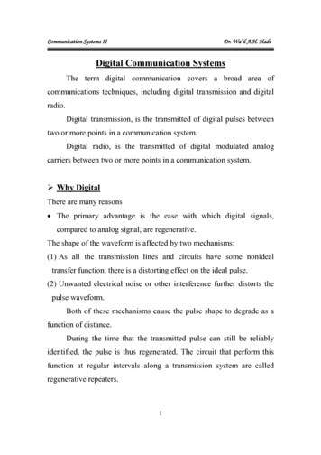
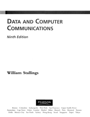
Harmonics – 1ModernCommunications A harmonic is a multiple of a fundamental frequency. In theDavid GoodwinUniversity ofBedfordshireDigitalCommunications20Amplitude Modulation90figure below, a fundamental frequency of 100 Hz is shownwith 31 harmonics (total of 32 “lines”).
Harmonics – 2 In this example, 20 harmonics are mixed together to form aModernCommunicationssaw-tooth waveformDavid GoodwinUniversity ofBedfordshireDigitalCommunications21Amplitude Modulation90
Fourier series expansionModernCommunications For periodic signal we use the Fourier series expansion as aDavid GoodwinUniversity ofBedfordshireDigitalCommunicationssimple way of frequency representation of such signals22Amplitude Modulation The Fourier series expansion of a general periodic signal x(t)with period T is defined as Trigonometric expansionx(t) a0 X[an cos (2πnf0 t) bn sin (2πnf0 t)]n 1 wherea0 an bn 901TZ2TZ2TZTx(t)dt0Tx(t) cos (2πnf0 t)dt0Tx(t) sin (2πnf0 t)dt0
Transmission FundamentalsComplex Plane-Complex NumbersModernCommunications Complex plane is a two dimensional representation of complexDavid GoodwinUniversity ofBedfordshireDigitalCommunications23Amplitude Modulationnumbers and complex signals. The general definition of acomplex number z is z a jb a is the real part and b the imaginary part of z, respectivelyand j is a non-real constant such that j 2 1 simply impliesa phase difference of 90 degrees An alternative and very common representation of complexnumbers is z a jb r cos θ jr sin θ rejθ where cos θ j sin θ ejθ , r is the amplitude and θ is thephase of za2 b2 , tanθ b/a, a r cos θ, b r sin θ, r 90
Complex exponential harmonic signalModernCommunicationsDavid GoodwinUniversity ofBedfordshireDigitalCommunications x(t) ej2πf t cos (2πf t) j sin (2πf t)24 It is a very useful signal used for frequency domain analysis.Its amplitude is equal to one whereas it rotates in thecomplex plane in the counter-clockwise direction with anangular frequency ω 2πfAmplitude Modulation90
Transmission FundamentalsFrequency domain analysis-Fourier SeriesModernCommunications For periodic signal we use the Fourier series expansion as aDavid GoodwinUniversity ofBedfordshireDigitalCommunicationssimpler way of frequency representation of such signals The Fourier series expansion of a general periodic signal x(t)25with period T is defined as Trigonometric expansionAmplitude Modulationx(t) a0 X[an cos (2πnf0 t) bn sin (2πnf0 t)]n 1 Complex exponential expansion Xx(t) cn e j2πnf0 tn wherecn 1TZT /2x(t)e j2πnf0 t dt T /2 Generally, the Fourier series expansion is a simpler way ofrepresenting periodic signals90
Frequency domain analysis-Fourier TransformModernCommunications Definition of frequency content: Frequency content of a timeDavid GoodwinUniversity ofBedfordshiredomain signal is the weighed superposition of all the complexexponential harmonic signals that accurately reconstruct theinitial time domain signal. The frequency content is defined through the well-knownFourier transform FZ F [x(t)] X(f ) x(t)e j2πnf0 t dtDigitalCommunications26Amplitude Modulation The original signal can be reconstructed by its Fouriertransform through the so-called Inverse Fourier transform F 1Z x(t) F 1 [X(f )] X(f )ej2πnf0 t dt Generally, the Fourier transform is a complex valued function90having both amplitude and phase. In the above definitions,the functions x(t) and X(f) are recognized as Fouriertransform pairs
Sine and Cosine Waves - 9ModernCommunicationsDavid GoodwinUniversity ofBedfordshireDigitalCommunications27 Two conceptsAmplitude Modulation The signal may be thought of as a time varying voltage, V(t) The angle, θ, is made up of a time varying component, ωt,and a supplementary value, φ, which may be fixed or varying Thus we have a signal V (t) A cos (ωt φ)90
Sine and Cosine Waves - 10ModernCommunicationsDavid GoodwinUniversity ofBedfordshireDigitalCommunications Time varying signal28Amplitude Modulation90
Back to our Sine Wave – 1Defining the WavelengthModernCommunicationsDavid GoodwinUniversity ofBedfordshireDigitalCommunications29Amplitude Modulation90
Back to our Sine Wave - 2ModernCommunicationsDavid GoodwinUniversity ofBedfordshireDigitalCommunications30Amplitude Modulation One revolution 360 degrees One revolution also completes one cycle (or wavelength) ofthe wave. So the “phase” of the wave has moved from 0 degrees to 360degrees (i.e. back to 0 degrees ) in one cycle.The faster thephase changes, the shorter the time one cycle (onewavelength) takes90
Back to our Sine Wave – 3Two useful equationsModernCommunicationsDavid GoodwinUniversity ofBedfordshireDigitalCommunications31Amplitude Modulation The time taken to complete one cycle, or wavelength, is theperiod, T. Frequency is the reciprocal of the period, that is f 1T Phase has changed by θ The rate-of-change of the phase,90dθ, is the frequency, f.dt
Sine Wave – 4ModernCommunications What do we mean “Rate-of-change of phase is frequency”?David GoodwinUniversity ofBedfordshireDigitalCommunications One revolution 360 degrees 2π radians 1 cycle32 One revolution/s 1 cycle/s 1 Hz Examples:Amplitude Modulation 720 degrees/s 2 revolutions/s 2 Hz 18,000 degrees/s 18,000/360 revs/s 50 revs/s 50 Hz90
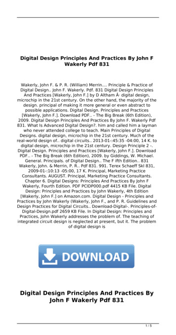
Simple Harmonic MotionModernCommunicationsDavid GoodwinUniversity ofBedfordshireDigitalCommunications33Amplitude Modulation Geometric derivation of simple harmonic motion. A point pmoves at constant speed on the circumference of a circle incounter-clockwise motion. Its projection OC on the verticalaxis XOY is shown at right as a function of the angle θ. Thefunction described is that of a sine wave.90
Sine Wave ContinuedModernCommunicationsDavid GoodwinUniversity ofBedfordshireDigitalCommunications Can think of a Sine Wave as a Carrier Signal, i.e. the signal34Amplitude Modulation90onto which the information is loaded for sending to the enduser A Carrier Signal is used as the basis for sendingelectromagnetic signals between a transmitter and a receiver,independently of the frequency
Carrier signals - 1ModernCommunicationsDavid GoodwinUniversity ofBedfordshireDigitalCommunications A Carrier Signal may be considered to travel at the speed of35light, c, whether it is in free space or in a metal wire Travels more slowly in most substancesAmplitude Modulation The velocity, frequency, and wavelength of the carrier signalare uniquely connected byc fλ where: c velocity of light (m/s) f frequency (1/s, Hz) λ wavelength (m)90
Carrier signals - 2ModernCommunicationsDavid GoodwinUniversity ofBedfordshireDigitalCommunications36 Example WAMU (National Public Radio) transmits at a carrierAmplitude Modulationfrequency of 88.5 MHz What is the wavelength of the carrier signal? Answer: c (3 108 )m/s f λ (88.5 106 ) (λ) Which gives λ 3.3898 3.4 m Remember: Make sure you are using the correct units90
Transmission FundamentalsWhy Digital Communications?ModernCommunications Analog TransmissionDavid GoodwinUniversity ofBedfordshireDigitalCommunications Each repeater attempts to restore analog signal to its original37form Restoration is imperfectAmplitude Modulation Distortion is not completely eliminated Noise & interference is only partially removed Signal quality decreases with number of repeaters Communications is distance-limited Still used in analog cable TV systems90
Transmission FundamentalsWhy Digital Communications?ModernCommunicationsDavid GoodwinUniversity ofBedfordshireDigitalCommunications Digital Transmission38 Regenerator recovers original data sequence and retransmitson next segment Then each regeneration is like transmitting for first time! Communications is possible over very long distances Digital systems vs. analog systemsAmplitude Modulation Less power, longer distances, lower system cost Monitoring, multiplexing, coding, encryption, protocols. . .90
Transmission FundamentalsWhy Digital Communications?ModernCommunications Analog transmission: all details must be reproducedaccuratelyDavid GoodwinUniversity ofBedfordshireDigitalCommunications39Amplitude Modulation Analog transmission: all details must be reproducedaccurately90 Simpler Receiver: Was original pulse positive or negative?
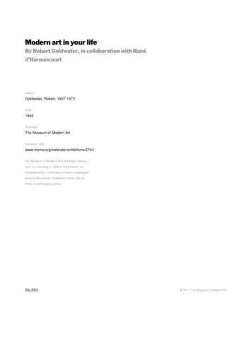
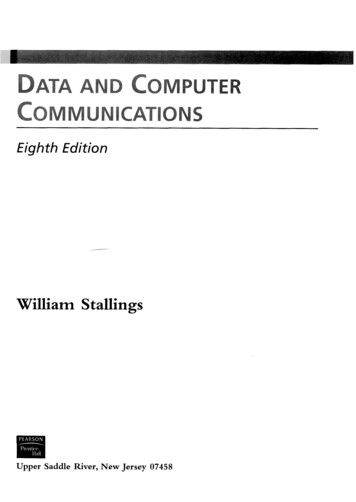
Transmission FundamentalsStructure of a Digital Communication SystemModernCommunicationsDavid GoodwinUniversity ofBedfordshireDigitalCommunications40Amplitude Modulation In a digital communication system the message produced by90the source is converted into a digital signal, i.e., a sequenceof binary digits. Source coding, channel coding and digital modulation arecarried out at the transmitter’s side Digital demodulation, channel decoding and source decodingare carried out at the receiver’s side
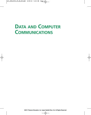
Transmission FundamentalsInformation SourceModernCommunicationsDavid GoodwinUniversity ofBedfordshireDigitalCommunications The information source produces41the message, i.e., the information,that is to be transmitted The output of the source can beAmplitude Modulationeither analog or digital data Examples of messages can be the following 90Earthquake wave: 0.01 10 HzNuclear explosion signal: 0.01 10 HzElectrocardiogram (ECG): 0 100 HzWind noise: 100 1000 HzSpeech: 100 4000 Hz (4 KHz)Audio: 20 20000 Hz (20 KHz)NTSC TV: 6 MHzHDTV: 10 MHz
Transmission FundamentalsSource CodingModernCommunications Source coding also called dataDavid GoodwinUniversity ofBedfordshireDigitalCommunications42Amplitude Modulationcompression is a process in whichthe output of the informationsource is converted into a digitalsignal, i.e., a sequence of binarydigits The sequence of binary digits iscalled information sequence90
Transmission FundamentalsChannel CodingModernCommunicationsDavid GoodwinUniversity ofBedfordshireDigitalCommunications43 Channel coding is a process thatadds redundancy (e.g, parity bits,repetition codes, etc.) in theinformation sequence to make theinformation more tollerant againstchannel impairments such asadditive noise, interferences and soon For example, a trivial channel coding scheme is each binarydigit of the information sequence to be repeated several timesAmplitude Modulation90
Transmission FundamentalsDigital ModulationModernCommunicationsDavid GoodwinUniversity ofBedfordshireDigitalCommunications Digital modulation acts as the44Amplitude Modulationinterface between the digitalsection of the transmission systemand the transmission medium(twisted pair, coaxial cable, radiochannel and so on) It maps the binary informationsequence into electrical signals When two signals are used to transmit the two digits (one for0, one for 1), this is called binary modulation When M 2b signals are used to transmitt b coded digits (asequence of 0’s and 1’s), this is called M-ary modulation90
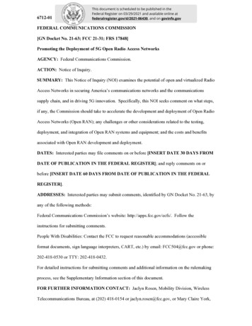
Transmission FundamentalsTransmission ChannelModernCommunications The transmission channel is theDavid GoodwinUniversity ofBedfordshireDigitalCommunicationsmedium that sends the signal fromthe transmitter to the receiver45 In the following, we see the maincategories of channels transmittingelectrical signalsAmplitude Modulation Wireless ElectromagneticChannel LF (30 300KHz,Navigation) MF/HF (300 3000KHz,AM/SW radio) VHF (30 300MHz, TV& FM radio) UHF (0.3 3GHz, TV,mobile phone) SHF (3 30GHz,90 EHF (30 300GHz,experimental com) Infrared (no frequencyallocation) Wired Media Twisted pair (0 10MHz) Coaxial cable(100K 500MHz) Optical fiber(180 370THz)
Transmission FundamentalsTransmission Channel: Electromagnetic SpectrumModernCommunicationsDavid GoodwinUniversity ofBedfordshireDigitalCommunications46Amplitude Modulation90
Transmission FundamentalsTransmission Channel: Mathematical ModelsModernCommunicationsDavid GoodwinUniversity ofBedfordshireDigitalCommunications47 The additive noise channel y(t) u(t) n(t)Amplitude Modulation The linear filter channel y(t) R u(τ )c(t τ )dτ n(t) The linear time variant filterchannelR y(t) 90 u(τ )c(τ, t τ )dτ n(t)
Transmission FundamentalsDigital DemodulationModernCommunicationsDavid GoodwinUniversity ofBedfordshireDigitalCommunications48Amplitude Modulation Digital demodulation transformsthe transmitted signal into asequence of binary digits thatrepresents estimates od thetransmitted binary symbols90
Transmission FundamentalsChannel DecodingModernCommunicationsDavid GoodwinUniversity ofBedfordshireDigitalCommunications49Amplitude Modulation Channel decoding attempts toreconstruct the original informationsequence according to knowledgeof the code used through thechannel coding process90
Transmission FundamentalsSource DecodingModernCommunicationsDavid GoodwinUniversity ofBedfordshireDigitalCommunications50Amplitude Modulation Source decoding attempts toreconstruct the original signal fromthe source according to knowledgeof the code used through thesource coding process90
Key Design Issues - 1ModernCommunicationsDavid GoodwinUniversity ofBedfordshireDigitalCommunications S/N51 Signal-to-Noise Ratio (Analog) Need to be above user’s threshold for Required QoSAmplitude Modulation C/N Carrier-to-Noise Ratio (Analog and Digital) Need to be above demodulation threshold for useful transferof information BER Bit Error Rate (Sometimes Bit Error Ratio) S/N Need to satisfy the Performance and AvailabilitySpecifications90
Signal-to-Noise Ratio - 1ModernCommunicationsDavid GoodwinUniversity ofBedfordshireDigitalCommunications52 Signal-to-Noise, written as S/N, is mainly used for AnalogAmplitude ModulationSystems S/N is specified at the Baseband of the Information Channel Baseband is a range of frequencies close to zero Information is what is sent to the user and the channel overwhich it is sent is the Information Channel90
Digression - UNITSModernCommunicationsDavid GoodwinUniversity ofBedfordshireDigitalCommunications53Amplitude Modulation Standard units to use are MKS M meters written as m K kilograms written as kg S seconds written as s Hence the velocity of light is in m/s The wavelength is in m And the frequency is in Hz hertz90
Carrier signals - 3ModernCommunications A Carrier Signal canDavid GoodwinUniversity ofBedfordshireDigitalCommunications carry just one channel of information (this is often called54Single Channel Per Carrier SCPC) Or carry many channels of information at the same time,Amplitude Modulationusually through a Multiplexer Note: The modulator has been omitted in these drawings90
Decibel (dB) Notation - 1ModernCommunicationsDavid GoodwinUniversity ofBedfordshireDigitalCommunications55Amplitude Modulation Historically the Bel, named after Alexander Graham Bell, is aunit of sound It was developed as a ratio measure: i.e., it compares thevarious sound levels The Bel was found to be too large a value and so a tenth of aBel was used, i.e., the decibel A decibel, or 1 dB, was found to be the minimum change insound level a human ear could detect90
Decibel (dB) Notation - 1ModernCommunicationsDavid GoodwinUniversity ofBedfordshireDigitalCommunications56 Question How do you get a dB value?Amplitude Modulation Answer Take the log10 value and multiply it by 10 Example One number is 7 times larger than another. The dB difference 10 log10 7 10 0.8451 8.5dB NOTE: Never quote a dB number to more than one place ofdecimals90
Decibel (dB) Notation - 2ModernCommunicationsDavid GoodwinUniversity ofBedfordshireDigitalCommunications57 Some things to remember A dB value is always 10 log10 ; it is never, ever, 20 log10 ,Amplitude Modulationhowever . . . 10log10 (x)a 10 a log10 (x) e.g. 10log10 (x)2 10 2 log10 (x) 20log10 (x) The dB ratio may be referenced to a given level, for example 1 W (unit would be dBW) 1 mW (unit would be dBmW)90
Decibel (dB) Notation - 3ModernCommunicationsDavid GoodwinUniversity ofBedfordshireDigitalCommunications58 Question An amplifier increases power by a ratio of 17:1, what is theAmplitude ModulationdB gain? Answer 10 log10 17 12.3 dB Question The amplifier is fed with 1W, how many watts are output? Answer 17 Watts which is equivalent to 12.3 dBW90
Decibel (dB) Notation - 4ModernCommunicationsDavid GoodwinUniversity ofBedfordshireDigitalCommunications59 Examples of dB notations of power, etc.Amplitude Modulation 90425 W 26.3 dBW425 W 425,000 mW 56.3 dBm0.3 W -5.2 dBW0.3W 300 mW 24.8 dBm24,500 K 43.9 dBK-273 K Error – you cannot take a logarithm of a negativenumber
Decibel - ExamplesModernCommunicationsDavid GoodwinUniversity ofBedfordshireDigitalCommunications60Amplitude Modulation90
Signal-to-Noise Ratio - 2ModernCommunicationsDavid GoodwinUniversity ofBedfordshireDigitalCommunications61Amplitude Modulation What S/N value gives a good reception? Telephone and TV channels require a minimum of 50 dB 50 dB ratio of 100,000 IE:the Signal power is 100,000 the Noise power Analog signals have “graceful degradation” characteristics90
Signal-to-Noise Ratio - 3ModernCommunicationsDavid GoodwinUniversity ofBedfordshireDigitalCommunications62Amplitude Modulation90
Signal-to-Noise Ratio - 4ModernCommunicationsDavid GoodwinUniversity ofBedfordshireDigitalCommunications63 The S/N is what the user perceives, but it is usuallymeasured at the demodulator outputAmplitude Modulation The C/N at the demodulator input will determine the outputS/N90
Carrier-to-Noise Ratio - 1ModernCommunicationsDavid GoodwinUniversity ofBedfordshireDigitalCommunications64 Carrier-to-Noise, written as C/N, is used for both Analog andAmplitude ModulationDigital Systems The Carrier signal has information from the sender impressedupon it, through modulation. The carrier, plus the modulatedinformation, will pass through the wideband portion oftransmitter and receiver, and also over the transmission path90
Carrier-to-Noise Ratio - 2ModernCommunicationsDavid GoodwinUniversity ofBedfordshireDigitalCommunications65Amplitude Modulation The C/N at the input to the demodulator is the key designpoint in any communications system90
Carrier-to-Noise Ratio - 3ModernCommunicationsDavid GoodwinUniversity ofBedfordshireDigitalCommunications66Amplitude Modulation90
Carrier-to-Noise Ratio - 4ModernCommunicationsDavid GoodwinUniversity ofBedfordshireDigitalCommunications Useful design reference for uncoded QPSK67Amplitude Modulation90 BER 10 6 at 10.6 dB input C/N to Demodulator
BER - 1ModernCommunicationsDavid GoodwinUniversity ofBedfordshireDigitalCommunications68 BER means Bit Error Rate, however some people refer to itAmplitude Modulationas the Bit Error Ratio (i.e. the ratio of bad to good bits) Strictly speaking, it is the Probability that a single Bit Errorwill occur BER is usually given as a power exponent, e.g. 10 6 , whichmeans one error in 106 bits90
BER - 2ModernCommunicationsDavid GoodwinUniversity ofBedfordshireDigitalCommunications69 A BER of 10 6 means on the order of one error in a page ofAmplitude Modulationa FAX message To improve BER, channel coding is used FEC codes Interleaved codes Communications systems are specified in many ways, but thetwo most common are performance and availability90
BER - 3ModernCommunicationsDavid GoodwinUniversity ofBedfordshireDigitalCommunications70 PerformanceAmplitude Modulation Generally specified as a BER to be maintained for a very highpercentage of the time (usually set between 98% and 99% ofthe time) Availability Generally specified as a minimum BER below which noinformation can be transmitted successfully - i.e. an outageoccurs90
BER - 4ModernCommunicationsDavid GoodwinUniversity ofBedfordshireDigitalCommunications71 What causes the change in BER? Since BER is determined by C/N, change in BER is causedAmplitude Modulationeither by Changes in C (i.e. carrier power level) Antenna loses track Attenuation of signal Changes in N (i.e. noise power level) Interference (see next slide) Enhanced noise input90
BER - 5ModernCommunicationsDavid GoodwinUniversity ofBedfordshireDigitalCommunications72Amplitude Modulation90
BER – 6Performance & AvailabilityModernCommunicationsDavid GoodwinUniversity ofBedfordshireDigitalCommunications73Amplitude Modulation90
BER – 7Performance & AvailabilityModernCommunicationsDavid GoodwinUniversity ofBedfordshireDigitalCommunications74Amplitude Modulation90
ModernCommunicationsDavid GoodwinUniversity ofBedfordshireDigitalCommunicationsAmplitude Modulation 7590Amplitude Modulation
What is Amplitude Modulation?ModernCommunicationsDavid GoodwinUniversity ofBedfordshireDigitalCommunicationsAmplitude Modulation 76 Amplitude modulation is the process of changing theamplitude of a relatively high frequency carrier signal inproportion with the instantaneous value of the modulatingsignal (information)90
Amplitude modulationModernCommunicationsDavid GoodwinUniversity ofBedfordshireDigitalCommunicationsAmplitude Modulation 7790
Linear modulation / Amplitude ModulationModernCommunicationsDavid GoodwinUniversity ofBedfordshireDigitalCommunicationsAmplitude Modulation 7890
Modulated signalModernCommunicationsDavid GoodwinUniversity ofBedfordshireDigitalCommunicationsAmplitude Modulation 7990
Amplitude spectraModernCommunicationsDavid GoodwinUniversity ofBedfordshireDigitalCommunicationsAmplitude Modulation 8090
Amplitude spectraModernCommunicationsDavid GoodwinUniversity ofBedfordshireDigitalCommunicationsAmplitude Modulation 8190
Amplitude spectraModernCommunicationsDavid GoodwinUniversity ofBedfordshireDigitalCommunicationsAmplitude Modulation 8290
Amplitude spectraModernCommunicationsDavid GoodwinUniversity ofBedfordshireDigitalCommunicationsAmplitude Modulation 8390
General idea of an AM modulatorModernCommunicationsDavid GoodwinUniversity ofBedfordshireDigitalCommunicationsAmplitude Modulation 8490
Modulation coefficientModernCommunicationsDavid GoodwinUniversity ofBedfordshireDigitalCommunicationsAmplitude Modulation 8590
Modulation coefficientModernCommunicationsDavid GoodwinUniversity ofBedfordshireDigitalCommunicationsAmplitude Modulation 8690
Modulation coefficientModernCommunicationsDavid GoodwinUniversity ofBedfordshireDigitalCommunicationsAmplitude Modulation 8790
Modulation by a Complex Information SignalModernCommunicationsDavid GoodwinUniversity ofBedfordshireDigitalCommunicationsAmplitude Modulation 8890
Modulation by a Complex Information SignalModernCommunicationsDavid GoodwinUniversity ofBedfordshireDigitalCommunicationsAmplitude Modulation 8990
AM Amplitude spectrumModernCommunicationsDavid GoodwinUniversity ofBedfordshireDigitalCommunicationsAmplitude Modulation 9090
Modern Communications David Goodwin University of Bedfordshire Digital 40 Communications Amplitude Modulation Transmission Fundamentals Structure of a Digital Communication System In a digital communication system the message produced by the source is converted into a digital signal, i.e., a sequence of binary digits.