Transcription
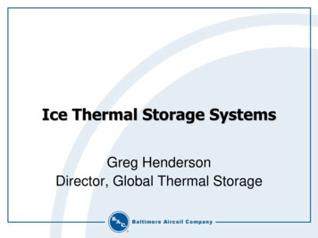
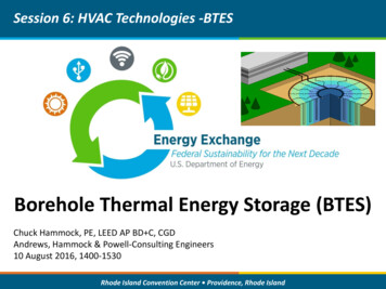
Thermal Energy Storage TechnologiesAuthors & Affiliations: Clifford K. Ho (Renewable Energy Technologies) and AndreaAmbrosini (Concentrating Solar Technologies), Sandia National Laboratories1. AbstractThermal storage technologies have the potential to provide large capacity, long-duration storageto enable high penetrations of intermittent renewable energy, flexible energy generation forconventional baseload sources, and seasonal energy needs. Thermal storage options includesensible, latent, and thermochemical technologies. Sensible thermal storage includes storing heatin liquids such as molten salts and in solids such as concrete blocks, rocks, or sand-like particles.Latent heat storage involves storing heat in a phase-change material that utilizes the large latentheat of phase change during melting of a solid to a liquid. Thermochemical storage converts heatinto chemical bonds, which is reversible and beneficial for long-term storage applications.Current research in each of the thermal storage technologies is described, along with remainingchallenges and future opportunities.2. Key TermsThermal storage, sensible storage, latent storage, thermochemical storage, long-duration storage3. Introduction3.1. Problem StatementIncreasing penetrations of intermittent renewable energy sources (e.g., photovoltaics [PV] andwind energy) have increased the need for energy storage technologies to accommodate dailyperiods of overgeneration and peak loads. These diurnal energy-storage requirements arecategorized in this chapter as short-duration and span periods from seconds to hours withcapacities ranging from kilowatts to gigawatts. Previous studies have suggested that thedecreasing costs of batteries and associated technologies may enable battery systems to meet theshort-duration needs of the grid with high penetrations of intermittent renewable energy systems[1, 2]. However, recent studies have shown that long-duration energy storage (days to months)will be needed to accommodate 100% renewable (or carbon-free) energy generation [3]. Inaddition, long-duration energy storage will be needed to increase the security and resilience ofthe electrical grid in the face of increasing natural disasters and intentional threats.3.2. Thermal Storage ApplicationsFigure 1 shows a chart of current energy storage technologies as a function of discharge timesand power capacity for short-duration energy storage [4]. Within the range of short-durationenergy storage capacities, applications include reserve and response services (1–100 kW),transmission and distribution support grid (100 kW–10 MW), and bulk power management (10MW–1 GW). Although thermal storage technology is included in the chart as cryogenic energystorage, hot thermal storage using sensible, latent, or thermochemical methods [5, 6] is not1
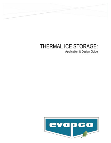
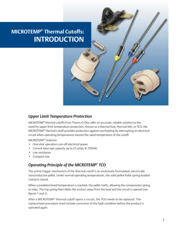
shown. Commercial concentrating solar power (CSP) using sensible heat storage hasdemonstrated the ability to provide on the order of 100 MW of power capacity over 10 hours ( 1GWh) for both grid support and bulk power management.Thermal storage technologies are also being considered for nuclear power plants to increase theflexibility of these traditionally baseload systems [6]. At times of low or negative electricityprices, heat (or electricity) generated by the nuclear reactor would be sent to thermal storage. Attimes of high electricity prices, the heat from the reactor and thermal storage would be used toproduce maximum electricity output (Figure 2). New Generation IV nuclear reactors deliverhigher temperatures to the power cycle relative to water-cooled reactors, which is beneficial forthermal storage because at higher temperatures, less storage material is required to deliver adesired amount of thermal power. In addition, the higher temperatures enable more efficientthermal-to-electric power conversion. Adding thermal energy storage to geothermal power plantsto increase flexibility and dispatchability has also been considered [7].Figure 1. Discharge time and capacity of various energy storage technologies [4]. Hot thermalstorage technologies are not shown but can provide hundreds of megawatts for many hours.2
Figure 2. Diagram illustrating how thermal storage can increase the flexibility of traditionalbaseload power plants that rely on thermal energy [6].3.3. Technology OverviewThe remainder of this chapter provides a summary of thermal storage technologies, which caninclude sensible, latent, and thermochemical systems. Sensible storage relies on a temperaturedifference within the storage medium to enable useful work to be performed, such as using hotmolten salt to heat water and generate steam to spin a turbine for electricity production. Latentstorage involves storing heat in a phase-change material that utilizes the large latent heat ofphase change, for example, during isothermal melting of a solid to a liquid, which requires heat,and subsequent freezing of the liquid to a solid, which releases heat, isothermally.Thermochemical energy storage (TCES) reversibly converts heat into chemical bonds using areactive storage medium. When the energy is needed, a reverse reaction combines the reactants,releasing energy. Table 1 summarizes the different thermal storage technologies and keyattributes.Table 1. Summary of thermal storage technologiesSensible Heat Storage[5, 8-12]Latent Heat Storage[5, 9, 10, 12, 13]ThermochemicalStorage[9, 11, 13]StoragemechanismEnergy stored astemperature difference insolid (e.g., concrete, rock,sand) or liquid media(molten salt)Energy stored using phasechange materials (e.g., salts,metals, organics)Energy stored inchemical bondsEnergyDensity 200 – 500 kJ/kg (for 200 – 400 Ctemperature differential) 100 – 200 kJ/kg fornitrate salts; 200 – 500kJ/kg for metals; 1000kJ/kg for fluoride salts 300 – 6,000 kJ/kg3
Sensible Heat Storage[5, 8-12] Demonstrated largeenergy capacity ( GWh) Inexpensive mediaAdvantages Solid media does notfreeze and can achieve 1000 CChallengesMaturityCost Requires insulation tomitigate heat losses Lower energy densityrequires larger volumes Molten salts freeze at 200 C.High 1/kg for molten saltsand ceramic particles 0.1/kg for rock andsands 1/MJ – 10/MJ(system capital cost)Latent Heat Storage[5, 9, 10, 12, 13] Good for isothermal orlow T applications Can provide large energydensity with combinedsensible and latent heatstorage Potential for corrosion For larger T, may needcascaded systems (addscosts and complexity) Low maturityLow 4/kg – 300/kg 10/MJ – 100/MJ(system capital cost) ThermochemicalStorage[9, 11, 13]Large energy densitiesSmall heat lossesPotential for long-termstorageCompact storagesystemOxide TCES Stable athigh temperatures ( 1000 C)Higher complexityLow maturityHigher capital costsMay require storage ofgaseous productsLow 10/MJ – 100/MJ(system capital cost)4. State of Current Technology4.1. Sensible heat storageSensible heat storage consists of heating a material to increase its internal energy. The resultingtemperature difference, together with thermophysical properties (density, specific heat) andvolume of storage material, determine its energy capacity (J or kWh):Esensible V cp (T )dTTHTC(1)Desirable features of sensible storage materials include large densities, (kg/m3), large specificheats, cp (J/kg-K), and large temperature differences between the hot and cold states, TH – TC(K). Key advantages include a low cost of sensible storage materials, high maturity level, andlarge energy capacities. Table 2 provides a summary of thermophysical properties of varioussensible solid and liquid storage media.4
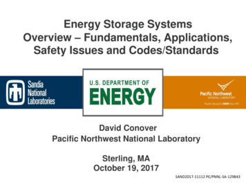
Table 2. Thermophysical properties of sensible storage media (adapted from [5]). Calculation ofvolumetric and gravimetric storage densities assume a temperature differential of 350 C.Storage icStorage 11311820794TemperatureRange ( C)ColdHotSolidsConcreteSintered bauxite particlesNaCICast ironCast steelSilica fire bricksMagnesia fire bricksGraphiteAluminum ate salts(ex. KNO3-0.46NaNO3)Therminol VP-1 Silicone oilCarbonate saltsCaloria HT-43 Sodium liquid metalNa-0.79K metal eutecticHydroxide salts (ex. 38573525065666213236764373471250575Commercial CSP plants that employ sensible thermal storage with over 1 GWh of storage havebeen deployed worldwide. For comparison, Figure 3 shows the total number of large-scalebattery demonstration facilities in the United States at the end of 2017 along with two CSPplants. Each CSP plant provides more energy storage capacity than all 100 PV demonstrationfacilities combined.5
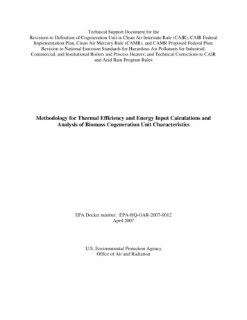
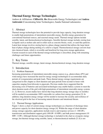
*U.S. Energy Information Administration (June 5, 2018)18001680Energy Storage Capacity le Battery Storage( 100 plants in U.S. at end of2017)Crescent Dunes CSP Plant(molten-salt storage)Solana CSP Plant(molten-salt storage)Figure 3. Comparison of energy storage capacity for battery and CSP plants Battery data fromU.S. Energy Information Administration [14].4.1.1. Current ImplementationCurrent implementation of high-temperature sensible heat storage for electricity production usesliquids (e.g., molten salts) and solids (concrete, rocks).4.1.1.1 LiquidMolten nitrate salt (60% NaNO3, 40% KNO3) is being used in commercial CSP plants around theworld to provide gigawatt-hours of thermal energy storage. It has a low vapor pressure, so it isnot pressurized at typical storage temperatures up to 600 C, and it can be pumped from onelocation to another.Figure 4 shows a photograph and schematic of the 110 MW Crescent Dunes CSP plant with 1.1GWh of thermal storage using molten nitrate salt. Molten salt is heated in a receiver on top of atower by concentrated sunlight from a field of heliostats. The hot molten salt ( 565 C) flows to ahot storage tank (right tank in Figure 4). When needed, molten salt is pumped from the hotstorage tank to a heat exchanger where it heats water and generates steam to spin aturbine/generator for electricity. The cooled molten salt ( 300 C) is pumped to a cold storagetank (left tank in Figure 4) and back to the receiver to be heated when the sun is shining. CSPplants can operate with large capacity factors (70–80%) and provide dispatchable energy.6
Solar to Thermal ConversionThermal StorageElectricity GenerationSolar ThermalReceiverHot StorageHeatExchangerHeliostat FieldPowerBlockCold StorageFigure 4. Top: Photo of 110 MW Crescent Dunes CSP plant with 1.1 GWh of thermal storage usingmolten nitrate salt [15]. Bottom: Schematic of sensible two-tank thermal storage system in a CSPplant.4.1.1.2 SolidSolid thermal storage has been used in several commercial and demonstration facilities. In 2011,Graphite Energy developed a 3 MWe CSP plant in Lake Cargelligo in New South Wales,Australia, that used graphite blocks in the receivers on top of multiple towers. The graphiteblocks in the receiver, irradiated by concentrated sunlight, served as both the storage system andboiler to generate steam for power production.EnergyNest, based in Norway, developed a concrete-based thermal energy storage system thatconsists of an array of modular pipes filled with concrete and steel tubes. The tubes carry heattransfer fluid that can heat the concrete when charging and extract heat from the concrete whendischarging to power a turbine/generator or provide process heating. The system can7
charge/discharge in 30 minutes and the stored energy can last for several days with less than2% heat loss per 24 hours for large-scale systems.Siemens Gamesa in Germany has developed a 130 MWht Electric Thermal Energy Storage(ETES) system comprises rocks stored in a building. Air is resistively heated using electricity(when price is low) and passed directly through the bed of rocks. The rocks are heated to 600 C, and, when needed, air is passed through the hot rocks to heat steam for a Rankine powercycle. The 130 MWht demonstration plant became operational in 2019, and the company isplanning a design for a 30 MW commercial pilot plant.4.1.2. ChallengesThe relatively low energy density of sensible-heat storage materials requires large volumes ofmaterial for large-capacity energy storage, which increases the overall storage cost. In addition,some power cycles that employ recuperation to increase the thermal-to-electric efficiency requirerelatively low temperature differentials between the hot and cold states of the storage material.For example, the supercritical CO2 recompression Brayton cycle requires a temperature increaseof only 200 C in the primary heat exchanger [16]. As a result, the required mass inventory ofstorage material must increase to deliver the same amount of energy for a lower temperaturedifferential, which increases costs. The target capital cost for the U.S. Department of Energy(DOE) CSP program is 15/kWh for the entire thermal storage system.Molten salts freeze at 200 C, which requires expensive trace heating to maintain allcomponents at temperatures well above the freezing point. If the salt freezes, flow can beblocked, and thawing must occur before operation can begin. Stress within the large storagetanks has also caused issues at CSP plants. Thermal gradients at the base of the tank can createthermomechanical stresses that damage the tank structure. Appropriate consideration ofthermomechanical stresses is critical to the design of large-scale thermal storage tanks.4.1.3. OpportunitiesA number of institutions have been pursuing small, sand-like particle-based thermal storage forCSP plants and stand-alone thermal energy storage systems. Unlike the previous solid-basedthermal storage systems, rather than passing air or a heat-transfer fluid through the storagemedia, the particles are heated directly and conveyed through a heat exchanger to heat theworking fluid [8]. The particles are lifted to the top of the receiver where they are irradiated andheated by concentrated sunlight. The hot particles flow into an insulated storage tank where theycan be held for hours or days. When needed, the particles are released through a particle heatexchanger to heat a working fluid that spins a turbine/generator for electricity production (Figure5).8
Particle elevatorParticle curtainParticle hotstorage tankParticle-toworking-fluid heatexchangerApertureParticle coldstorage tankFalling particle receiverFigure 5. Illustration of a high-temperature falling particle receiver with tower-integrated storageand heat-exchanger for dispatchable electricity production [17]Like the other solid-based thermal storage technologies, inexpensive particle storage canaccommodate increasing penetrations of renewables by allowing heat to be stored whenelectricity demand is low, and then using that stored heat to produce electricity when demandand prices are higher. This time-shifting of energy production and use can increase the flexibilityof traditional baseload power plants, including nuclear and geothermal.Solid storage media has the advantage of being inert, inexpensive, non-corrosive, and easy tohandle. In addition, many solid materials exhibit a much wider operating temperature range thanmolten salts. Rock, sand, and sintered bauxite have all been utilized in thermal storage systemsand can operate in sub-freezing to 1000 C temperatures. Large volumes of bulk solid materialcan also provide self-insulation from the cooler ambient environment. As the volume of the bulkstorage tank increases, the ratio of its surface area to volume decreases, which reduces heat loss.So, large storage tanks or containment systems yield both performance benefits and economiesof scale.Pumped thermal energy storage uses electricity in a heat pump to transfers heat from a coldreservoir to a hot reservoir similar to a refrigerator. When electricity is needed, the heat pump isreversed to allow the heat from the hot reservoir to drive a heat engine and spin aturbine/generator. The large potential temperature differences between the hot and coldreservoirs can enable highly efficient power cycles. Malta, a spinoff from Google X, is designinga pumped-thermal energy storage system (Figure 6).9
Figure 6. Malta’s pumped thermal energy storage concept {Malta, 2020 #13799}MIT is investigating another storage technology that would use cheap or excess electricity tosensibly heat molten silicon to ultra-high temperatures in large, insulated graphite tanks. Themolten silicon would be held at “cold” temperatures of 1900 C (above its melting point of1414 C) and heated with electrical heating elements to nearly 2400 C, where it is stored in asecond “hot” tank. When electricity is needed, the molten silicon is pumped from the hot tankthrough tubes that emit thermal radiation to multijunction photovoltaic cells that generateelectricity. The cooled molten silicon is then collected in the cold storage tank.4.2. Latent heat storageLatent heat storage systems use the latent heat of phase change to store energy. Latent heat offusion is the energy required to change the state of substance from a solid to a liquid, and latentheat of evaporation is the energy required to change the state of substance from a liquid to a gas.Salts and metals can be melted, and the combined sensible and latent heat can be used to storethe added thermal energy. Table 3 summarizes the thermophysical property values of differentlatent-heat storage materials. The latent heat of reaction (kJ/kg) shown in the second columnwould be added to the sensible heat capacity in Eq. (1) to determine the total heat capacity oflatent heat storage materials being heated from one state to another. In most cases, the materialsare solid/liquid phase change materials that are stored as liquids that can subsequently releaseenergy when converted back to a solid state. Some liquid/gas substances (nitrogen and oxygen)are also shown because cryogenic “liquid air” storage has also been demonstrated for grid energystorage applications.10
Table 3. Thermophysical properties of phase-change storage materials at standard conditions,unless otherwise noted (adapted from [5])Storage MediumSpecificHeat(kJ/kgK)1.21.5-Latent orReactionHeatDensityMelting(kJ/kg)(kg/m3)Point ( C)Liquid/Solid Phase Change oilingPoint( mAluminum alloys (ex. Al0.13Si)alloys (ex. Cu-0.29Si)CopperCarbonate salts (ex. Li2CO3)Nitrate salts(ex. KNO3-0.46NaNO3)Bromide salts (ex. KBr)Chloride salts (ex. NaCI)Fluoride salts (ex. LiF)Lithium hydrideHydroxide salts (ex. 414-18004140Liquid/Gas Phase Change en0.922131140(liquid)--1832132434.2.1. Current ImplementationPhase change materials (PCMs) have been encapsulated in spheres to form packed beds ofencapsulated PCMs [9]. Heat-transfer fluid can be passed through the packed-bed of spheres tocharge or discharge energy to/from the encapsulated PCMs. The phase change occurs at nearlyisothermal conditions, so this method is useful for applications where the heat addition needs tooccur at a specific temperature. At larger temperature ranges, cascaded PCM systems can bedesigned, but with additional complexity and cost. To date, encapsulated PCM systems havebeen tested and demonstrated at small scales. Commercial systems have not been demonstrated.Molten silicon systems have been developed to exploit the large heat of phase change whenmelting/solidifying silicon ( 1800 kJ/kg). The Australian company, 1414 Degrees, has designedthermal energy storage systems ranging from 10–200 MWh, and they began operating aprototype facility in 2019. The systems melt silicon at 1400 C and recoup the latent energyduring solidification to power combined cycles.On the opposite end of the temperature scale, Highview Power has demonstrated cryogenicenergy storage using “liquid air” at demonstration facilities with 2.5 kWh (300 kW peak power)and 15 MWh (5 MW peak power) of energy storage. The system operates by using electricity tocool air from ambient temperatures to -195 C using the Claude Cycle. The liquified air is storedat atmospheric pressure in large vacuum-insulated tanks. The volume occupied by the liquid airis 1,000 times less than that of air at ambient conditions. When electricity is needed, the liquidair is pumped at high pressures through a heat exchanger that exposes the liquid air to ambienttemperatures (or waste heat from an industrial heat source). The liquid air vaporizes, causing11
sudden expansion, which spins and turbine/generator for electricity production. The heatexchanger can consist of a gravel bed that serves as a cold store of low-temperature material aftergiving up its energy to vaporize the liquid air. The low-temperature material can then be used tohelp cool the air during the next refrigeration cycle.4.2.2. ChallengesChallenges with PCMs include relatively high costs and narrow operating temperature ranges.Using PCMs to provide energy to a heat engine will typically require a cascaded system withmultiple PCMs with different melting points. The use of molten silicon at high temperaturesprovides challenges with materials containment and heat loss. Phase-change systems must stillbe well insulated to prevent heat loss and subsequent phase change.4.2.3. Opportunities1414 Degrees appears to have successfully developed a prototype molten-silicon system thatexploits very high latent heats of fusion. Other systems and materials that can exploit high latentheats of fusion at low costs may provide alternative thermal storage capabilities.4.3. Thermochemical storageThermochemical energy storage (TCES) is a promising storage technology, especially at hightemperatures ( 700 C), as it allows for the storage of heat through chemical reactions, forexample, the breaking/reforming of bonds. A conceptual illustration of TCES is shown in Figure7 [18].Figure 7. Schematic of steps involved in TCES: charging, storage, and discharging [18]The thermochemical storage reaction, in its most basic form, can be written asAB ΔHrxn A B12(2)
In this equation, Reactant AB is dissociated into Products A B via the application of heat (heatof reaction shown in Table 3) in an endothermic reaction. The individual products can be storedseparately for an indefinite amount of time. In times of thermal demand, A B recombine in anexothermic reaction, releasing heat (the reaction proceeds to the left).The TCES process compared to other thermal storage technologies is summarized in Table 1.The potential benefits of TCES include (1) enabling more efficient high-temperature powercycles (sCO2 or air Brayton) that are inaccessible using current molten salt technologies, (2)potential higher-density and long-term storage, and (3) higher exergy. In addition, certain TCESprocesses (e.g., redox-active oxides) are also amenable to generating hydrogen via watersplitting. The hydrogen can then be used on-site to run a fuel cell for back-up generation. ForTCES to be a practical storage technology, the materials must have a large reaction enthalpy andfast reaction kinetics, high thermal conductivity, good cyclic stability without the formation ofunwanted phases or side reactions. They should also consist of abundant and economicallyinexpensive elements [19-22].4.3.1. ImplementationA variety of potential TCES processes exist, though no TCES material has been implemented onan industrial scale. TCES can be applicable over a wide range of temperatures and conditions.Heat source, the type of power cycle, operating temperature, and receiver configuration allinfluence the selection of a candidate TCES material. Table 4 lists the most promising TCESreactions by type, reaction temperatures, enthalpies, and gravimetric storage energies. Theoperating temperatures and storage densities are representative values, but can differ dependingon operating conditions, such as pressure, as well as the morphology of the solid species. Thesolid species can be particles, monoliths, or supported on inert or reactive scaffolds to avoidsintering or deactivation of the material [23].Table 4. Candidate materials systems for thermochemical energy storageTemperatureRange ( eDensity(MJ/m3)178850-127317642491SrCO3(s) ΔH SrO(s) CO2(g)234900-1200300-10001200-1500BaCO3(s) ΔH BaO(s) CO2(g)273 1290Ca(OH)2(s) ΔH CaO(s) H2O(g)10440060014061640Mg(OH)2(s) ΔH MgO(s) H2O(g)81350-13401396HydridesMgH2(s) ΔH Mg(s) H2(g)75300-480Mg2FeH6(s) ΔH 2Mg(s) Fe(s) H2(g)74300-50028802106 (theo.),1921 (expt)20885768 (theo)2344(expt)ReactionEnthalpy(kJ/mol)CaCO3(s) ΔH CO2(g) CaO(s) CO2(g)Storage MediumCarbonatesHydroxides13
TemperatureRange ( eDensity(MJ/m3)77300-50011603142NaMg2H3(s) ΔH NaH(s) Mg(s) H2(g)87430-5851721 1721NaMgH2F(s) ΔH NaF(s) Mg(s) H2(g)97510-60514161968CaH2(s) ΔH Ca(s) H2(g)1861000-140035877374AmmoniaNH3(g) ½ N2(g) 3/2 H2(g)67400-70039242682-2Co3O4 (s) ΔH 6CoO(s) O2(g)2BaO2(s) ΔH 6BaO(s) O2(g)20579900693-7808444746Mn2O3(s) ΔH 4Mn3O4(s) O2(g)321000204-4CuO(s) ΔH 2Cu2O(s) O2(g)641030-ReactionEnthalpy(kJ/mol)Mg2NiH4(s) ΔH Mg2Ni(s) 2H2(g)Storage MediumRedox Active Oxides*Ca0.95Sr0.05MnO3(s) ΔH Ca0.95Sr0.05MnO2.7(s) 0.15 O2(g)-CaAl0.02Mn0.8O3 (s) CaAl0.02Mn0.8O2.68 (s) 0.16O2(g)368200-1250390La0.3Sr0.7Co0.9Mn0.1O3(s) ΔH La0.3Sr0.7Co0.9Mn0.1O2.54(s) 0.23 O2(g)350200-12502501000-555-*Storage values for redox materials do not take into account the sensible heat storage contributions of these oxide materials.Table 5 lists the pros and cons of each type of cycle as well as its technology status.Table 5. Advantages and drawbacks of TCES materials (adapted from [16])MaterialAdvantagesDrawbacksCarbonates Cheap, abundant, and non-toxic High energy density High operating temperatures (up to1700 K) suitable for hightemperature power generation Less reversibility Low cyclic stability (10–20cycles) SinteringHydroxides Low material cost Abundant Non-toxic Agglomeration of material Side reactions with CO2MetalHydrides High energy density High reversibility A lot of experimental feedback on H2storage and heat pump applications Oxides High reaction enthalpy (205 kJ/mol) Wide operating temperature (400–1473 K) Toxicity of some products(Co3O4/ CoO)14Poor reaction kineticsHydrogen embrittlementSinteringHigher material costTechnology StatusLab-scale (fixed orfluidized-bedreactors) and pilotscale (CaLtechnology for CO2capture)Lab-scale and pilotscalePilot-scaleLab-scale
MaterialAdvantagesDrawbacks Low operating pressure (0–10 bar)No catalystNo side reaction (BaO/BaO2)High reversibility (500 cycles(Co3O4/CoO; 1000 cycles CaxSr1-xAlO3) Can take advantage of sensible heatto increase storage density AmmoniaSynthesis/Dissociation Easy to control No side reactions Vast industrial experience (HaberBosch) Toxic High cost of containment Lower volumetric energydensity Higher operatingpressuresSulfurBasedCycles Corrosive Toxic Highly protectivecontainment is requiredCheap and commercially availableStable storageEnergy density of 9 MJ/kgSulfur is a cost-effective material( 200 /t) Vast industrial experienceTechnology StatusCost of productsHeat transferSinteringLow maturity levelPilot-scaleLab-scaleAlthough a variety of potential TCES processes exist, no TCES system has yet beenimplemented on an industrial scale. Several bench-scale and pilot-scale demonstrations havebeen reported, several of which are described later in this chapter. A number of recent reviewsalso provide comprehensive explanations of these processes [13, 18, 23-25]. One of the mostdeveloped TCES systems is the ammonia-based reaction, which has been studied for over 40years, most notably at Australian National University (ANU). Figure 8 shows a schematic for aproposed storage system [26]. Ammonia (NH3) is dissociated on-sun into H2 and N2 gases whichcan be stored indefinitely in a pressurized vessel. When heat is required, the gases are reacted tore-synthesize NH3 in an exothermic process similar to the industrial Haber-Bosch process. In1999, ANU tested a 10 kWt closed-loop solar ammonia TCES system over the course of 5 hours,demonstrating solar dissociation and re-synthesis of NH3 with storage and heat recovery [27]. In2018, Chen et al. proposed and evaluated—using parametric modeling—an NH3 TCES systemutilizing supercritical steam as a heat transfer fluid [28].15
In another conceptual design, Schmidt et al have performed multiple lab-scale tests on thecalcium hydroxide [Ca(OH)2] system demonstrating dehydration and rehydration (450 C and550 C, respectively) of 20 kg of Ca(OH)2. They attained a maximum thermal power of 7.5 kWthwith an air outlet temperature of 450 C for 35 minutes [29]. In ensuing experiments, theyshowed that the outlet temperature could be increased to 600 C if the system was operated at 450kPa. Based on these results, they proposed and thermodynamically analyzed a concept forintegration into a CSP plant for up to 15 hours of storage, shown in Figure 9 [30].Figure 8. Ammonia dissociation and storage schematic [24]Figure 9. Conceptual process design of an indirectly heated Ca(OH)2 thermochemical reactor in aCSP plant configuration [30]16
Recently, there has been an increased interest in metal oxide TCES systems due to their
Figure 4. Top: Photo of 110 MW Crescent Dunes CSP plant with 1.1 GWh of thermal storage using molten nitrate salt [15]. Bottom: Schematic of sensible two-tank thermal storage system in a CSP plant. 4.1.1.2 Solid Solid thermal storage has been used in several commercial and demonstration facilities. In 2011, Graphite Energy developed a 3 MW e