Transcription
Matt Behrendhttp://home.earthlink.net/ electronxlc/How a Tesla Coil worksOn this page, I will explain the basic theory of how a Tesla coil works. Below is the Table of Contents for this page.zzzzzzzDescription of ComponentsHow the Components OperateLC CircuitsVoltage GainResonant RiseOscillation and TuningQuarter Wavelength FrequencyDescription of ComponentsA Tesla coil is a high-voltage air-core resonant transformer. A Tesla coil has 6 basic components. The first is theprimary transformer, which is a high-voltage iron-core transformer. The second is the tank capacitor, which is a high-voltagecapacitor that is usually homemade, but can be purchased for a high price from commercial suppliers. The third is the sparkgap, basically two wires separated by a small gap of air. The fourth is the primary coil consisting of about 10 to 15 turns ofthick heavy gauge wire wound around the base of the secondary coil. The fifth is the secondary coil, and it consists of manyhundreds of turns of relatively thin, small gauge enameled wire. The primary and secondary coils make up an air-coretransformer. That means that there is no iron core inside of the coils. The sixth basic component is the toroid. It is usually analuminum doughnut-shaped object, and placed on top of the secondary coil. The high-voltage sparks radiate in all directionsfrom the toroid out into the air.How the Components OperateThe primary transformer converts the AC line voltage (120/240 volts AC) to over 10,000 volts. This energy is used tocharge the high-voltage capacitor. The capacitor is wired in series with primary coil to the output of the transformer. Whenthe voltage builds up enough to break down the spark gap, a spark will bridge the spark gap and complete the circuit betweenthe capacitor and the primary coil by shorting out the transformer. A spark ionizes the air, causing it to become much moreconductive. All the energy stored in the capacitor will be forced through the primary coil. The process of charging thecapacitor and firing the spark gap occurs very rapidly. The spark gap may fire from 120 to over 1000 hertz, but 120 hertzdelivers the largest energy bursts. When the energy is transferred to the primary coil, an electromagnetic field is generatedand surrounds the secondary coil. The secondary coil absorbs this energy and magnifies the voltage further. The resultingvoltage could be a couple hundred thousand volts for small coils, or millions for very large ones. It is very important toefficiently ground the coil. Grounding the coil connects it to the second plate (the earth) of the toroid capacitor. The bottomwire of the secondary coil is grounded via a heavy gauge wire that leads directly to a ground rod. The top wire of thesecondary is connected to the toroid. There are usually a couple inches between the top winding of the secondary and thetoroid.The tank capacitor is wired in series with the primary coil. This does not affect the charging of the capacitor since theprimary has a very low reactance at 60 Hz. The transformer is better protected from RF noise by this configuration than if thecapacitor and spark gap positions were reversed.
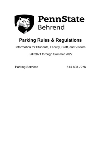
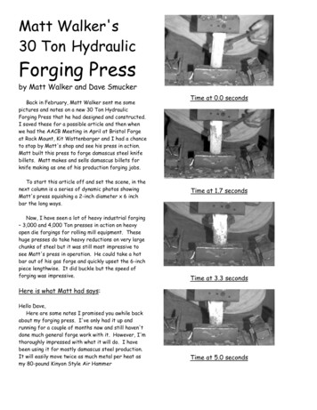
A schematic diagram of a Tesla coil.LC CircuitsTesla coils are composed of two LC circuits. Both of those circuits must be tuned to the exact same frequency foroptimum efficiency. The first LC circuit is the tank circuit. The tank circuit is an oscillator composed of the capacitor, sparkgap, and primary coil. The second LC circuit, which is a series resonant circuit, is the secondary coil and the toroid.An LC circuit contains an inductor (a coil) and a capacitor respectively. An LC circuit is at resonance where theinductive reactance of the inductor equals the capacitive reactance of the capacitor at the same frequency. Reactance is theresistance to the AC waveform. Another way to define reactance, is the resistance to any change in voltage or current flowfrom the current instantaneous value. Alternating current is constantly changing because it flows in the form of a sine wave.Inductors resist changes in current flow and capacitors resist changes in voltage. Reactance is not the same as simple DCresistance. DC resistance is the resistance to the flow of electrons through a material, not the resistance to changes in voltageor current. The reactance of a capacitor or an inductor is based upon its electrical value and the frequency at which itoperates. Finding the reactance of a component is explained on the calculations page. The graphic below shows therelationship between frequency, reactance, and resonant frequency. Capacitive reactance is denoted XC and inductivereactance is denoted XL.For any two given values of L and C their reactances will only be equal at one frequency. In a shock excited oscillatorsuch as the tank circuit, the circuit will oscillate at that frequency where the reactances are equal. The circuit oscillates at thatfrequency because the circuit is balanced at that frequency. When the reactances are equal, both components have an equalcharge and discharge time delay. It takes the inductor the same amount of time to discharge into the capacitor as it did for thecapacitor to discharge into the inductor. The amount of time it takes for the discharge cycles to complete determines thenumber of cycles per second, which is the frequency of the oscillator circuit.The toroid is actually one plate of a virtual capacitor. The second plate of the virtual capacitor is the earth itself, becausethe bottom wire of the secondary coil is grounded. The larger the toroid, the more capacitance it has. The toroid must havethe right amount of capacitance so that its reactance equals the secondary coil's inductive reactance at the Tesla coil'sdesigned resonant frequency. The secondary coil itself also has capacitance. The wire of the coil has capacitance to ground,
and there is capacitance between each turn of the coil. Although these capacitances are extremely minute, at high frequenciesthey become quite significant. These effects on the circuit are discussed in more detail on the calculations page.These graphics show the distribution of capacitance throughout the secondary circuit.Voltage GainThe Tesla coil achieves a great gain in voltage in a very different way than a conventional transformer. A transformer'schange in voltage is dependent upon the turns ratio of the primary and secondary coils. If the primary coil of a transformerhas 5 turns and the secondary coil has 100 turns, then the secondary voltage will be 20 times that of the primary. This doesnot fully apply to the interaction of the primary and secondary coils of a Tesla coil. Instead, a Tesla coil's voltage gain isbased upon the different impedances of the primary and secondary circuit components. For example, a 0.06 µF tank capacitorhas an impedance of 27 ohms at 100 kHz. The toroid has a capacitance of 30 pF and an impedance of 53,000 ohms at100kHz. The greater impedance causes a greater voltage potential and less current. This behavior is better explained by theconservation of energy. The energy you put into a system is the energy you get out if losses are ignored.CapacitanceJ 0.5 V2 CInductanceJ 0.5 I2 LJ joules of energy storedV peak charge voltageI peak currentC capacitance in faradsL inductance in henriesThe joule is a unit used for measuring the amount of energy stored in an inductor or capacitor. The formulas are derivedby integrating the power (in watts) flowing through the component over time. The approximate output voltage of a Tesla coilcan be found by this formula. The formula assumes that all energy is transferred from the primary circuit to the secondarycircuit without any losses. That can't happen, so the actual voltage will be somewhat less than the calculated value. Don't usean RMS value in these equations, the peak values are required.The secondary circuit voltage is found by setting the energy in the primary equal to the energy in the secondary, andsolving for secondary voltage. The secondary capacitance (CS) includes both the topload and the coil's self capacitance.VS peak secondary voltage
VP peak charge voltage of tank capacitorCS secondary capacitance in faradsCP tank capacitance in faradsNote that energy in equals energy out. I want to emphasize the fact that Tesla coils do not produce "free energy". Somepeople may argue that energy was produced since the high voltage transformer charged the tank capacitor to 10 kV at 100mA and their secondary coil runs at 100 kV and several amps. This is a difference in power, not energy. Power is the rate atwhich energy is moving, and energy is power multiplied by time. It took 1/120 of a second to charge the tank capacitor but ittook a mere 1/400000 of a second for the tank capacitor to move the same energy into the primary coil.There are certain limitations to voltage gain. Using an extremely small toroid will not give a greater spark length or peakvoltage. If there were no topload the output voltage would theoretically be at a maximum. However, when there is littlecapacitance, the coil will "break out" (ionize the air and create a spark) at a lower voltage. If an arc to ground occurs whenthe secondary is charged halfway, then most of that energy is spent in the arc and dissipated as heat. The secondary continuesto be charged by the primary, but that energy is used to maintain the short arc rather than to continue building up the circuit'sstored energy. This condition does not allow the secondary circuit to reach its peak potential, and spark length is severelydecreased. Also, spark length is not merely based upon voltage, but is a function of both voltage and current. The toroidshould be much greater than the self capacitance of the coil. I have noticed that a topload any less than the self capacitance ofthe secondary coil greatly decreases spark length. Also, if the topload is too great, then it may not be able to break out at thegiven power level.The primary and secondary circuits must resonate at the same frequency, because all of the primary circuit's energy isnot transferred to the secondary in a single 1/4 cycle of the AC waveform. The low coefficient of coupling makes it necessaryfor each cycle of energy coupled to the secondary to build upon the existing energy already transferred. This condition iscalled resonant rise, and it requires both circuits to have the same resonant frequency.In an LC circuit that is being continuously supplied with power, the voltage will be equal to the product of Q and E,where Q is the quality factor of the inductor, and E is the applied voltage. In a Tesla coil, the power supplied to the secondarycircuit is limited to the joules stored in the tank circuit. When all energy has been transferred, the peak voltage is found by theenergy formula.Resonant RiseResonant rise occurs in a series LC circuit when the frequency of the AC waveform that feeds the circuit is equal to theresonant frequency of the LC circuit.The inductive and capacitive components in a circuit cause a phase shift between the waveform of the current flowingthrough the component and the voltage drop across the component. In a purely resistive circuit, the current is in phase withthe voltage. As the input voltage to the resistor increases, so does the current flowing through it (Ohm's law).In a purely inductive circuit, the current waveform lags the voltage waveform by 90 , 1/4 of the sine wave. In other words,the voltage waveform leads the current waveform by 90 .
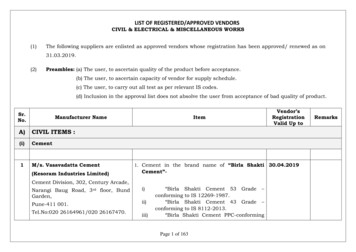
In a purely capacitive circuit, the current leads the voltage, or the voltage wave lags the current wave by 90 .In a circuit containing a combination of resistance and capacitance or inductance, the phase angle between the voltageand current waveforms of the entire circuit is some number less than 90 , depending on the component values. The totalimpedance and the phase angle of an LCR circuit is found by vector addition, but that will not be covered on this page. In atuned resonant circuit, the reactive components have a canceling effect, and the phase angle is zero (the waveforms are inphase).In any parallel LC circuit, the voltage drops of all components are in phase and equal, while the current waveform ofeach component is out of phase (by 90 ), and the magnitude of those waves may differ. In any series LC circuit, the currentwaveform flowing through the entire circuit remains constant, and the voltage drops of the L and C components are out ofphase with the current. The magnitude of the voltage drops may vary. The secondary circuit is a series resonant circuit withthe induced primary energy as the source.A Parallel LC circuit.A series LC circuit.The voltage drop of a component is the voltage potential that exists on the two leads of the component. The constantRMS voltage drop of an L or C component is found by multiplying its reactance by the current flowing through it (Ohm'slaw). In a series circuit at resonance, the reactances of the components, and therefore the voltage drops are equal. The currentwaveform is the same for each component. The capacitor voltage lags it by 90 , and the inductor voltage drop leads it by 90 .Therefore, the voltage drops are exactly opposite (180 out of phase), and equal in magnitude. This causes the reactive loadsin the series resonant circuit to exactly cancel each other out. This allows the maximum amount of current possible to flowthrough the circuit unrestricted by the reactive components. The only impedance that limits current flow remaining in theseries circuit is the DC resistance of the wire the inductor is wound from. An inductor always contains some value ofresistance in its wire, and some value of inductive reactance (based on the inductance value), and these two impedances act ina series configuration.Since the opposite voltage drops exactly cancel each other out, and only the resistance is left, the energy being suppliedby the primary sees the secondary circuit as a low-resistance load. This causes the current flow to increase, and thus thevoltage drops also. It is in this manner that the primary builds upon what it has already transferred to the secondary, until allenergy has been coupled to the secondary circuit.This graphic shows the current (voltage/reactance) in a series LCR circuit in relation to thefrequency of the voltage waveform applied to it. At the resonant frequency, the circuit's currentand compopnent voltage drops are at maximums.
Because of the way the primary and secondary coils are loosely coupled, they do not behave in the same way as an ironcore transformer. The induced energy in the secondary coil acts as a voltage source placed in series with the secondary coiland toroid capacitor. The primary coil (tank circuit) must be tuned to resonate at exactly the resonant frequency of thesecondary circuit for maximum efficiency.This graphic shows the induced voltage as an AC source to the secondary series resonant circuit.Resonant rise is commonly misunderstood to occur over multiple "bangs" (a single firing of the spark gap), however thisis not true. All of the examples and explanations of resonant rise in this paper describe the accumulation of energy in a singlebang, where each cycle of the oscillation in one circuit builds upon the energy in the other circuit. The energy that istransferred to the secondary circuit in one bang is quickly dissipated and is not stored long enough for the next bang to buildupon it. Once the spark gap quenches (stops conducting), the tank capacitor begins to charge again and any energy left in thesecondary circuit is converted to RF radiation and heat (from arcs and wire resistance). The duration of the oscillationgenerated is very short compared to the charge time of the tank capacitor. When running a Tesla coil, you will probablynotice that the maximum spark length grows in the first couple of minutes when it is first turned on. Although this wouldappear to be caused by the next bang building upon the previous, it is actually the result of the ionization of the air. As thecoil runs, it fills the room with gasses that are more conductive. The arcs also create ionized channels that are more prone tobreak down with a spark on the next cycle. For this reason, a greater number of firings per second may increase a Tesla coil'smaximum spark length.Oscillation and TuningThe output waveform of a Tesla coil that is commonly referred to as "ringing" is caused by the oscillatory response ofthe tank circuit and secondary resonant circuit. Oscillation is the process where an interchange of energy takes place betweenthe inductor and the capacitor in a tuned resonant circuit. This oscillation occurs in the tank circuit and in the secondarycircuit.The firing of the spark gap is the electrical equivalent to striking the side of a bell with a hammer. The LC circuit is likethe bell. A bell, when struck, will ring at a particular musical tone. The physical properties of the bell determine thefrequency of its tone, just like the capacitance and inductance of a circuit determine the frequency of the circuit. The tankcircuit will continue to "ring" for as long as the arc across the spark gap lasts.When the capacitor is charged to its peak voltage, the spark gap fires. The capacitor then discharges its energy into theprimary coil. The capacitor starts off at its peak voltage and is discharged to zero volts, forming 1/4 cycle of the tank circuit'sresonant frequency. As the capacitor is being discharged, the voltage drop is decreasing and current flowing through thecircuit is increasing, causing the field strength of the primary coil to rise. The primary coil stores this energy in the form of itselectromagnetic field. When the current flowing through the primary coil reaches its peak and the capacitor voltage is zero(because the capacitor is drained), current flow begins to fall because the capacitor can no longer supply current. The primarycoil resists this decrease in current flow by producing emf (electromotive force). This emf is caused by the collapsing of thecoil's magnetic field as the current flowing through it drops. A coil's magnetic field is sustained by current flow. The emfvoltage causes current to flow in the same direction and the primary coil charges the capacitor with its emf at the opposite ofthe capacitor's original polarity. Now that the capacitor is charged at the new polarity, it also discharges into the primary coilat that new polarity, causing the electromagnetic field of the primary coil to change polarity. As the emf energy stored in thecapacitor drops to zero, the primary produces emf again, causing the capacitor to be charged at its original polarity, and thecycle repeats itself. The oscillations continue to repeat until the spark gap is quenched, or the circuit runs out of energy (insecondary circuit).This back and forth recycling of energy can be compared to the swinging of a pendulum. The pendulum starts off inneutral position, pointing straight up and down. When it is pushed left it swings to the left until it peaks, and then swings
back to the right. It goes past the neutral position, peaks, and swings back to the left again. It continues swinging, traveling alittle less distance each cycle until it runs out of energy or is stopped.Below is a graphic of how oscillation behaves. The diagram shows the polarity of charge, the direction of current flow,and pieces of the current flow wave generated by each part of the cycle. The sine wave shown is in relation to the flow ofcurrent when oscillation begins.The result of the oscillations is a damped sine wave. Like the pendulum analogy, each cycle is weaker in magnitude thanthe previous. The decreasing of each cycle is caused by losses within the components of the LC circuit. The wave is alsodampened by the transfer of energy to the secondary circuit. Losses occur because of the resistance of the wire in primarycoil, not its impedance (inductive reactance), and the dissipation factor of the capacitor. For the tank capacitor, you shoulduse a very low loss dielectric; "leaky" capacitors waste energy. The copper conductor of the primary coil offers significantresistance because of the skin effect. At high frequencies, electricity flows near the surface of a conductor more than throughits center. The electrical current may only penetrate the conductor by a few mils, making the actual resistance much higherthan the DC resistance of the wire. The solution to this problem is to use a conductor with maximum surface area. Below is agraphic of the damped sine wave produced in an LCR circuit. If there were no losses within the circuit, the oscillations wouldcontinue indefinitely and there would not be a dampening effect (excluding that of energy transfer), but such a condition doesnot exist.Damped sine wave graphic.It is very important for the primary coil to resonate at the same frequency as the secondary coil so that each pulse fromthe ringing of the primary is in sync with the secondary coil. This situation is like pushing a swing set. You must give theswing a push at the same frequency that it is moving back and forth in order to maintain its motion. If the swing is flying
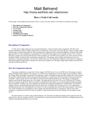
toward you and you give it a push before it is ready to go back the other way, then you will cancel out the motion and theswing will stop.The secondary resonant circuit of the secondary coil and toroid is an oscillator. Although the secondary circuit ismagnetically induced with the primary circuit's energy, the secondary circuit can ring at a different frequency that isindependent of the primary circuit. The oscillatory response of the secondary circuit operates in the same manner as in theprimary circuit. The difference in the secondary circuit is that its excitation source is the primary coil, rather than the initialcharge of a capacitor. Throughout the oscillations, the primary coil builds upon the oscillation of the secondary circuit byresonant rise. This is why it is absolutely critical that the primary circuit should resonate at the same frequency as thesecondary circuit. Just as the circuits reinforce each other when they are in tune, they can cancel out the resonant rise in thesecondary circuit if they are out of tune.The graphics below show the voltage waveforms of the tank circuit (pink) and the secondary circuit (blue). These areclose representations of the waveforms produced by a Tesla coil. I created these graphics with Excel, using a mathematicalequivalent to the waveforms I viewed with my oscilloscope.Notice how the energy in the secondary circuit gradually builds up to a peak. At that point, the secondary begins totransfer energy back to the primary circuit (oscillation between the two circuits). The spark gap quenches at the point wherethe graph of the primary circuit ends. The graph of the secondary shows the circuit ringing down after that point. There is nomore interaction between the primary and secondary circuits, because the continuity of the primary has been broken. Thesecondary's remaining energy is converted to heat and radiated RF energy, creating a damped sine wave.In these graphs, the spark gap has quenched just before the third notch. A notch is each point in time when all of the tankcircuit's energy has been transferred to the secondary circuit. It is ideal, although difficult, to achieve first notch quenching.This is important, because the longer the energy stays in the circuit, the more time is allowed for heat losses to waste energy.The tank circuit is the greatest source of loss, especially the spark gap. The tank circuit operates on hundreds of amps,causing the resistance of the circuit to dissipate a great amount of energy as heat. The amount of power lost is equal to I2 R,where I is current and R is resistance. The frequency of the oscillations between the primary and secondary is determined by
the coefficient of coupling, the tuning, and less significantly, the losses.In order to achieve the longest spark length (the goal of most coilers), it is necessary for the spark to break out at the firstnotch. This requires that the topload be of the correct size to only allow break out to occur at the peak voltage of the firstnotch. A given toroid will charge to a specific potential before it will allow the air surrounding it to break down and form aspark to ground. The optimum toroid size is usually found by experimentation, as it is affected by many factors.It is important to note that these waveforms are produced by a Tesla coil that is not arcing to ground. If there were aspark to ground, the waveforms would be quite different, but still similar. At the point in time when the arc completed itspath to ground, the energy level of the secondary would drop very quickly, and would not increase further. Any energy thatthe primary could continue to supply would be consumed in maintaining the arc. There would also not be any furtheroscillation between the circuits, since the secondary would never reach a peak energy level after the arc struck ground.Quarter Wavelength FrequencyFor a long time, it has been believed that Tesla coils are governed by the principles of the quarter wavelength theory.Much work has also been done in the recent years to model the secondary coil using transmission line theory. Both modelsseem to deviate from measurements others have taken. The lumped component model used for designing Tesla coils workswell, but it is not capable of describing the internal behavior of the secondary coil. Modeling the operation of the secondarycoil is not a simple task. Some complexities of the secondary coil are the magnetic coupling between adjacent turns, thedistribution of capacitance between turns, capacitance to ground, capacitance from windings to toroid, and the added lumpedcapacitance of the toroid to ground. The secondary coil and toroid compose a system, which by itself deserves attention.Modeling of this system will explain the uneven voltage distribution along the coil and the phase angle between current at thebase and top of the coil that has been observed by some people. Accurate models will provide greater insight into this part ofthe Tesla coil and aid in optimizing design. The following is a basic introduction to 1/4 wavelength theory for antennas andhow it may relate to secondary coil operation. It is not necessary to design a Tesla coil to resonate at the 1/4 wavelengthfrequency of its windings.A monopolar antenna most efficiently radiates its RF energy when it is operating at its 1/4 wavelength frequency. Theoutput of the antenna is at its peak when the maximum voltage is at the top of the antenna while maximum current is on thebottom. Maximum current occurs at the point on the sine wave when voltage is at a minimum, and minimum current occursat the point when voltage is at a maximum. The graphic below depicts the voltage and current waves on a monopolarantenna. These waveforms do not represent the actual instantaneous RF waves flowing through the antenna, but rather theirpeak values at each point along the length of the antenna. These are called standing waves.Monopolar antennas can also operate at odd multiple harmonics of the 1/4 wavelength frequency. Harmonic waveforms areshown on the two antennas below.
Antennas with 3/4 and 5/4 wavelengths.An analogy to this condition would be the waves that can be induced into a rope. One end of a long rope is fastened to apole (or anything), while a person holds the other end in his hand. If the person swings the rope from side to side very rapidlyat an appropriate frequency, standing waves can be seen in the motion of the rope at harmonics to the frequency that theperson is swinging it.If the antenna was not operating at its 1/4 wavelength frequency or a harmonic, then when the point of maximum currentwas on the bottom of the antenna, the point of maximum voltage would either be before or past the end of the antenna. Thisresults in a decrease in radiated energy.Electricity travels at the speed of light. If a coil has a length of wire "X", then the quarter wavelength frequency of thatcoil will be the frequency at which 1/4 of its cycle is completed when the electricity travels the distance "X".Below is a formula for calculating the 1/4 wavelength frequency of an antenna. Simply solve for frequency or length.The variable 'W' is multiplied by 4, because 4 times the 1/4 wavelength of wire is the distance spanned by a full cycle of the1/4 wavelength frequency. The wavelength of a single cycle multiplied by the number of cycles per second (1/4 wavelengthfrequency) will be the distance traveled by electricity in one second.4WF (5,280)(186,000)W the secondary coil's wire length in feetF the quarter wavelength frequency of the secondary coil in hertz186,000 the speed of light in miles per second5,280 feet in a mileIt is critical to the efficiency of a Tesla coil to have all the components properly in tune with each other. Having just alittle too much or too less of any electrical value can have a drastic effect on the output of your coil. The calculations pageexplains the steps involved in designing an efficient, tuned Tesla coil and finding the necessary values for each component.
Tesla Coil CalculationsOn this page of my site, I will explain how to design a Tesla coil to achieve the highest voltage gain possible with maximumefficiency. Computing all the component values for optimum performance is the most critical part of building a Tesla coil. ATesla coil is a finely tuned resonant circuit. Simply slapping all the components together with random values will not get youanywhere. Get out your calculator, because there is a lot of math involved in this.Table of ContentszzzzzPrimary TransformerTank CapacitorPrimary coilSecondary coilToroidThere are two main ways to design a Tesla coil. The first is to start with the transformer, and the second is to start withthe
A Tesla coil is a high-voltage air-core resonant transformer. A Tesla coil has 6 basic components. The first is the primary transformer, which is a high-voltage iron-core transformer. The second is the tank capacitor, which is a high-voltage capacitor that is usually homemade, but can be purchased for a high price from commercial suppliers.