Transcription
Chapter 15Unilateral and Bilateral Rehabilitationof the Upper Limb Following Strokevia an ExoskeletonJacob Rosen, Dejan Milutinović, Levi M. Miller, Matt Simkins,Hyunchul Kim, and Zhi LiAbstract Recent studies reported positive effects of bilateral arm training on strokerehabilitations. The development of novel robotic-based therapeutic interventionsaims at recovery of the motor control system of the upper limb, in addition to theincrease of the understanding of neurological mechanisms underlying the recoveryof function post stroke. A dual-arm upper limb exoskeleton EXO-UL7 that iskinematically compatible with the human arm is developed to assist unilateral andbilateral training after stroke. Control algorithms are designed and implemented toimprove the synergy of the human arm and the upper limb exoskeleton. Clinicalstudies on the robot-assisted bilateral rehabilitations show that both the unilateraland bilateral training have a positive effect on the recovery of the paretic arm.Bilateral training outperforms unilateral training by a significant improvement ofmotion range and movement velocities.Keywords Unilateral/bilateral stroke rehabilitation Upper limb exoskeleton Human arm Kinematics DynamicsJ. Rosen ( ) D. Milutinović M. Simkins Z. LiDepartment of Computer Engineering, University of California, Santa Cruz, CA 95064, USAe-mail: rosen@ucsc.edu; dejan@soe.ucsc.edu; msimkins@soe.ucsc.edu; zli12@ucsc.eduL.M. MillerCarbon Design Group, Seattle, WA, USAe-mail: levimakaio@gmail.comH. KimApple Inc., Cupertino, CA, USAe-mail: hyunchul78@gmail.com405P. Artemiadis (ed.), Neuro-Robotics: From Brain Machine Interfacesto Rehabilitation Robotics, Trends in Augmentation of Human Performance 2,DOI 10.1007/978-94-017-8932-5 15, Springer Science Business Media Dordrecht 2014
406J. Rosen et al.15.1 IntroductionStroke is a leading cause of long-term neurological disability and the top reason forseeking rehabilitative services in the U.S. Challenges in rehabilitation after stroke,especially in the chronic phase are two-fold: the first is the development of systemsfor intense delivery of targeted rehabilitative interventions based on neural plasticitythat will facilitate recovery and the second is to understand neural reorganizationthat facilitates the recovery of function. Whereas in the acute phase post stroke,medical management focuses on containing and minimizing the extent of the injury,in the chronic phase post stroke, neural plasticity induced by learning/trainingis the fundamental mechanism for recovery. The development of novel roboticbased therapeutic interventions aims at facilitating neural plasticity and inducingsustainable recovery of the motor control system of the upper limb. In addition,studies on the synergy of the human are and wearable robotic system (e.g., an upperlimb exoskeleton) improve the understanding of neurological mechanisms whichaim to maximize the recovery of function post stroke.15.1.1 Bilateral Robotic System and TreatmentResearch studies suggest that manual bilateral movements in which both armsand hands move simultaneously in a mirror image fashion or work simultaneouslywhile performing a bilateral task have profound effects on the reorganization of theneural system due to inherent brain plasticity. Using such a therapeutic approach forstroke patients is based on the understanding that both brain hemispheres (damagedand undamaged) are going through a natural recovery process, as well as neuralreorganization following a learning-based therapy. In spite of significant scientificevidence, translating a mirror image bilateral therapeutic approach into an intense(high dosage) physical rehabilitation treatment regime has been difficult. A therapistadministering this regime is challenged to simultaneously control the 16 degrees offreedom (DOF) of both arms (14 DOF) and hands (2 DOF limited to 3-point chucktype grasping).When considering bilateral symmetric movement training as an option fortherapy, there are two aspects to its efficacy. The first aspect relates to neuroscience.Based on experiments relating to bilateral symmetric manual coordination usingtrans-cranial magnetic stimulation and kinematic modeling, symmetric movementmight reduce inhibitions between the left and right hemispheres [1, 2]. In otherwords, bilateral symmetric movements have been found to increase cross-talk in thecorpus callosum. In that vein, multiple studies have demonstrated the effectivenessof mirror therapy. Using mirror therapy, stroke survivors were able to improvefunction based on the optical illusions of their paretic arm moving normally [3, 4].Based on such research, it has been proposed that symmetric movement trainingmight exploit such coupling thereby allowing for an increased use of undamaged
15 Unilateral and Bilateral Rehabilitation of the Upper Limb Following. . .407ipsilateral projections [5]. In this way, symmetric movement training might improvethe recovery process after a CVA. With respect to clinical outcomes, the results aresomewhat mixed. It is admittedly difficult to detect improvement. For individualswho have chronic motor impairment, improvement after therapy is often subtle.Standard care, unilateral and bilateral movement training have all been shown toresult in some improvement. However, distinguishing between training modalitiesis difficult and the differences are small. To that end, there is virtually no data(such as brain imaging) relating to neurological activity and bilateral therapy. Forthese reasons, it remains uncertain if bilateral symmetric therapy is truly betterthan unilateral therapy in the sense that there is more or less cross-talk betweenthe hemispheres. More to the point, there is no conclusive evidence that bilateralsymmetric movement training has a neurological basis.Beyond neurological considerations, there are factors that distinguish the efficacyof bilateral and unilateral movement training. Bilateral movement training wasshown to have better results than unilateral movement training in terms of therange of motion (ROM). One explanation for this difference is that the pareticarm was provided robotic assistance, while in the unilateral case, no assistance wasprovided. Subjects also reported that they preferred assistance [6]. While it is truethat a robot can provide assistance for unilateral movement training, the controlalgorithms and game designs become much more constrained. During movementtraining, providing assistance that moves the arm through large angles might makethe therapy feel unpredictable and might raise safety concerns. However, when theparetic arm is made to move symmetrically with the less affected arm, the subject isin control, and the game play is more predictable and the assistance is more natural.Therefore, bilateral training provides a flexible control paradigm for unstructuredassistance.There are two approaches for bilateral training. One involves full assistance [7]and the other requires partial assistance [6]. For full assistance, the paretic arm isforced into symmetric motion. Using this approach, the subjects may focus entirelyon their less affected limb in order to play therapy games or to complete tasks.The subjects might use a minimum of effort to move their paretic arm, and whatmovements they do make will have little to no effect on the game play or taskcompletion. Bilateral symmetric movement training with partial assistance allowsthe robot to provide some help for the paretic arm. However, the subjects cannotquite play the game or complete the task with their paretic arm unless they providesome voluntary effort. Subjects also perceived better outcomes for full assistancethan partial assistance [6].Bilateral symmetric movement training does have the potential to aggravatespasticity [6]. The cause for this relates to the speed of motion. It is known thatrapid flexion and extension of spastic joints can intensify existing spasticity. Thisin turn can result in pain, weakness, and reduced coordination. When subjectsperform symmetric movements, their less affected arm might move too rapidly.In turn, as the robot attempts to maintain symmetry, the paretic arm might movetoo quickly thus aggravating spasticity. The largest effects were evident in the hand.Therefore, bilateral symmetric movement is recommended for individuals who have
408J. Rosen et al.mild spasticity. If robotic training is used with assistance, be it bilateral or unilateral,care is needed not to move the paretic arm too fast.15.1.2 Robot-Assisted Stroke RehabilitationRecently research results have demonstrated that robotic devices can deliver effective rehabilitation therapies to patients suffering from the chronic neuromusculardisorders [8–10]. MIT-MANUS is one of the successful rehabilitation robotswhich adopted back-drivable hardware and impedance control as a robot controlsystem [11]. ARMin is a 7-DOF upper limb exoskeleton developed in ETH Zurichand the University of Zurich. This robot provides visual, acoustic and hapticinterfaces together with cooperative control strategies to facilitate the patient’s activeparticipation in the game. The lengths of the upper arm, lower arm, hand and theheight of the device are adjustable to accommodate patients of different sizes. Therehabilitation site and robotic system are wheelchair accessible. Pneu-WREX isa 6-DOF exoskeleton robot developed in UC Irvine. This robotic system adoptedpneumatic actuators [12]. Although the pneumatic actuator is harder to controldue to its non-linear characteristics, it produces relatively large forces with a lowon-board weigh [13]. The robot interacts with the virtual-reality game T-WREXbased on a Java Therapy 2.0 software system. Arizona State University researchersdeveloped a robotic arm, RUPERT (Robotic Upper Extremity Repetitive Therapy)targeting cost-effective and light-weight stroke patient rehabilitation [14, 15]. Thedevice provides the patient with assistive force to facilitate fluid and naturalarm movements essential for the activities of daily living. The controller for thepneumatic muscles can be programmed for each user to improve their arm andhand flexibility, as well as strength by providing a repetitive exercise pattern.In our previous work [16], the seven-DOF exoskeleton robot UL-EXO7 [8, 17, 18]was exploited as a core mechanical system for the long-term clinical trial ofthe bilateral and unilateral rehabilitation program. The controllers equipped inUL-EXO7 provided the assistive force to help patients make the natural armposture based on the work in [19, 20]. For the objective and fine-scale rehabilitationassessment, a new assessment metric, an efficiency index, was introduced to tell thetherapist how close the patient’s arm movements are to the normal subject’s armmovements.15.1.3 Objective and Paper StructureThis chapter describes the EXO-UL7 – an upper limb exoskeleton system andits clinical applications to bilateral stroke rehabilitation. Section 15.2 reviews thekinematic design of the EXO-UL7 with considerations in its compatibility withthe kinematics of the human arm. Based on the kinematic modeling of the human
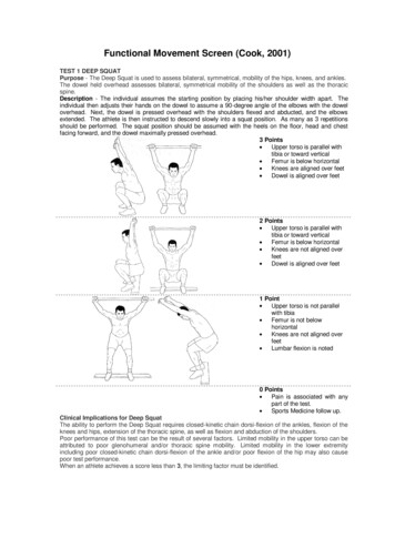
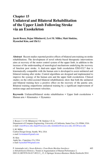
15 Unilateral and Bilateral Rehabilitation of the Upper Limb Following. . .409arm, the forward and inverse kinematics are derived. The control architectures areaddressed, including the control algorithms for admittance control, gravity compensation, inter-arm teleoperation and redundancy resolution. Clinical studies onrobot-assisted bilateral rehabilitations are presented in Sect. 15.3, with a comparisonof the outcomes of unilateral and bilateral training.15.2 An Upper Limb Exoskeleton: EXO-UL715.2.1 System OverviewThe kinematics and dynamics of the human arm during activities of daily living(ADL) have been studied to determine specifications for exoskeleton design(see Fig. 15.1). Articulation of the exoskeleton is achieved by seven single-axisrevolute joints which support 99 % of the range of motion required to performdaily activities. Three revolute joints are responsible for shoulder abductionadduction, flexion-extension and internal-external rotation. A single rotationaljoint is employed at the elbow, creating elbow flexion-extension. Finally, thelower arm and hand are connected by a three-axis spherical joint resulting inwrist pronation-supination, flexion-extension, and radial-ulnar deviation. As aFig. 15.1 The upper limb exoskeleton EXO-UL7 with seven DOFs, supporting 99 % of the rangeof motion required to preform daily activities
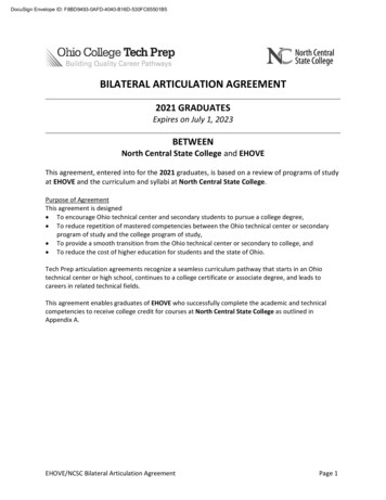
410J. Rosen et al.human-machine interface (HMI), four six-axis force/torque sensors (ATI IndustrialAutomation, model-Mini40) are attached to the upper arm, the lower arm, thehand and the tip of the exoskeleton. The force/torque sensor at the tip of theexoskeleton allows measurements of the interactions between the exoskeleton andthe environment [8, 9, 21].15.2.2 Kinematic Design of the Upper Limb ExoskeletonEXO-UL715.2.2.1Kinematic Modeling of the Human ArmThe upper limb exoskeleton EXO-UL7 is designed to be compatible with the humanarm kinematics. The human arm is composed of segments linked by articulationswith multiple degrees of freedom. It is a complex structure that is made up of bothrigid bone and soft tissue.Although much of the complexity of the soft tissue isdifficult to model, the overall arm movement can be represented by a much rigidbody model composed of rigid links connected by joints. Three rigid segments,consisting of the upper arm, lower arm and hand, connected by frictionless joints,make up the simplified model of the human arm. The upper arm and torso are rigidlyattached by a ball and socket joint. This joint enables shoulder abduction-adduction(abd-add), shoulder flexion-extension (flx-ext) and shoulder internal-external (intext) rotation. The upper and lower arm segments are attached by a single rotationaljoint at the elbow, creating elbow flx-ext. Finally, the lower arm and hand areconnected by a 3-axis spherical joint resulting in pronation-supination (pron-sup),wrist flx-ext, and wrist radial-ulnar (rad-uln) deviation. Models of the human armwith seven DOFs have been widely used in various applications, including renderinghuman arm movements by computer graphics [22, 23], controlling redundantrobots [24, 25], kinematic design of the upper limb exoskeletons [18, 26, 27], andbiomechanics [28–30]. These models provide a synthesis of proper representationof the human and the exoskeleton arm as redundant mechanisms along with andadequate level of complexity.The kinematics and dynamics of the human arm during activities of dailyliving (ADL) were studied in part to determine engineering specifications for theexoskeleton design [8]. Using these specification, two exoskeletons were developed,each with seven DOFs. Each exoskeleton arm is actuated by seven DC brushedmotors (Maxon) that transmit the appropriate torque to each joint utilizing a cablebased transmission. The mechanisms are attached to a frame mounted on the wall,which allows both height and distance between the arms to be adjusted. Articulationof the exoskeleton is achieved about seven single axis revolute joints – one foreach shoulder abd-add, shoulder flx-ext, shoulder int-ext rotation, elbow flx-ext,forearm pron-sup, wrist flx-ext, and wrist rad-uln deviation. The exoskeleton jointsare labeled 1–7 from proximal to distal in the order shown in Fig. 15.2. With sevenjoint rotations, there is one redundant degree of freedom.
15 Unilateral and Bilateral Rehabilitation of the Upper Limb Following. . .411Fig. 15.2 Exoskeleton axes assignment relative to the human arm. Positive rotations about eachjoint produce the following motions: (1) combined flx/adb, (2) combined flx/add, (3) int rotation,(4) elbow flx, (5) forearm pron, (6) wrist ext, and (7) wrist rad devThe fundamental principle in designing the exoskeleton joints is to align therotational axis of the exoskeleton with the anatomical rotations axes. If more thanone axis is at a particular anatomical joint (e.g. shoulder and wrist), the exoskeletonjoints emulate the anatomical joint interaction at the center of the anatomical joint.Consistent with other work, the glenohumeral (G-H) joint is modeled as a sphericaljoint composed of three intersection axes [31]. The elbow is modeled by a single axisorthogonal to the third shoulder axis, with a joint stop to prevent hyperextension.Exoskeleton pron-sup takes place between the elbow and the wrist as it does. Finally,two intersecting orthogonal axes represent the wrist. The ranges of motion of theexoskeleton joints support 99 % of the ranges of motion required to perform dailyactivities [8].Representing the ball and socket joint of the shoulder as three intersecting joinsintroduces of singularities that are not present in the human arm model. A significantconsideration in the exoskeleton design is the placement of singularities [24]. Thesingularity is a device configuration in which a DOF is lost or compromised as aresult of the alignment of two rotational axes. In the development of a three DOF
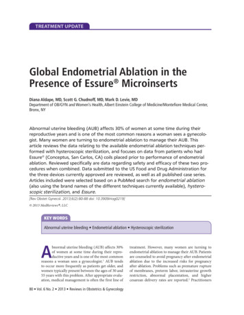
412J. Rosen et al.Fig. 15.3 Two singularities exist in the exoskeleton device, one when joints 1 and 3 align and theother when joints 3 and 5 align. (a) The orientation of joint 1 places the singularity at the shoulderin an anthropomorphically difficult place to reach. (b) Joints 1 and 3 align with simultaneousextension and abduction of the upper arm by 47:5ı and 53:6 ı . (c) Similarly, the same singularitycan be reached through flexion and adduction by 132:5ı and 53:6ı . (d) Alignment of joints 3 and5 naturally occurs only in full elbow extensionspherical joint, the existence or nonexistence of singularities will depend entirelyon the desired reachable workspace. Spherical workspace equal to or larger thana hemisphere will always contain singular positions. The challenge is to placethe singularity in an unreachable, or near-unreachable location, such as the edgeof the workspace. For the exoskeleton arm, singularities occur when joints 1 and3 or joints 3 and 5 align. To minimize the frequency of this occurrence, theaxis of joint 1 is positioned such that singularities with joint 3 take place onlyat locations that are anthropometrically hard to reach. For the placement shownin Fig. 15.3a, the singularity can be reached through simultaneous extension andabduction of the upper arm by 47:5ı and 53:6ı , respectively (see Fig. 15.3b).Similarly, the same singularity can be reached through flexion and adduction by132:5ı and 53:6ı , respectively (see Fig. 15.3c). The singularity between joints 3
15 Unilateral and Bilateral Rehabilitation of the Upper Limb Following. . .413Fig. 15.4 (a) Given a fixed wrist position in a 3D workspace, the arm plane formed by thepositions of the shoulder (Ps ), the elbow (Pe ) and the wrist (Pw ) can move around an axis thatconnects the shoulder and the wrist due to the kinematic redundancy. (b) The redundant DOF canbe represented by a swivel angle and 5 naturally occurs only in full elbow extension, i.e., on the edge of the forearmworkspace (see Fig. 15.3d). With each of these singularity vectors at or near theedge of the human workspace, the middle and majority of the workspace is free ofsingularities [8, 9].15.2.2.2Representation of the Redundant Degree of FreedomGiven the position (x, y, z) and the orientation ( x , y , and z ) of a target in a3-dimensional (3D) workspace, the human arm has a redundant DOF which allowsthe elbow to move around an axis that goes through the center of the shoulderand the wrist joints. This redundant DOF provides the flexibility in human armpostures when completing the tasks defined in the 3D workspace. When appliedto controlling the upper limb exoskeleton, a swivel angle is used to represent theredundant DOF. It specifies how much the elbow position pivots about the axis thatgoes through the center of shoulder and center of wrist, when the hand has a specificposition and orientation.As shown in Fig. 15.4, the arm plane is formed by the positions of the shoulder,the elbow and the wrist (denoted by Ps , Pe and Pw , respectively). The direction ofthe axis that the arm plane pivots about (denoted by n) is defined as:nDPw PsjjPw Ps jj(15.1)
414J. Rosen et al.Table 15.1 Denavit-Hartenberg (DH) Parameters for upper limb exoskeletonRobotLeft armRight armi 101234560123456i12345671234567 i 2 2 2 2 2 2 2 2 2 2 2 2 2 2ai00000000000000di000L10L20000 L10 L20 i 1 C 32:94ı 2 C 2 28:54ı 3 C 53:6ı 4 5 2 6 C 2 7 C 1 32:94ı 2 2 28:54ı 3 53:6ı 4 5 C 2 6 C 2 7 C The plane orthogonal to n can be determined given the position of Pe . Pc is theintersection point of the orthogonal plane with the vector Pw Ps . Pe Pc is theprojection of the upper arm (Pe Ps ) on the orthogonal plane. u is the projection of anormalized reference vector a onto the orthogonal plane, which can be calculated as:uDa .a n/njja .a n/njj(15.2)The swivel angle , represents the arm posture, can be defined by the anglebetween the vector Pe Pc and u. The reference vector a is suggested to beŒ0; 0; 1 T such that the swivel angle D 0ı when the elbow is at its lowest possiblepoint [32].15.2.2.3The Forward and Inverse Kinematicsof the Upper Limb ExoskeletonThis section derives the forward and inverse kinematics of the EXO-UL7 exoskeleton. Table 15.1 shows the Denavit-Hartenberg (DH) parameters of the upper limbexoskeleton, which are derived using the standard method (see [33]). The joint anglevariables are i (i D 1; ; 7). L1 and L2 are the length of the upper and lowerarms, respectively. The forward kinematics derives the transformation matrix 07 T ,which provides the position and the orientation of the wrist of the exoskeleton withrespect to the base frame Tbase :
15 Unilateral and Bilateral Rehabilitation of the Upper Limb Following. . .Table 15.2 Base rotation ofthe upper limb exoskeletonbaseT7Left armRight arm X (ı )132.5132.5D Tbase 01 T 12 T 23 T 34 T 45 T 56 T 67 T32r11 r12 r13 Pwx6r21 r22 r23 Pwy 77D64r31 r32 r33 Pwz 50 0 0 1415 Y (ı )45 45 Z (ı )9090(15.3)In order to move the singularity out of the range of the daily movements of thehuman arm, the bases of the two robotic arms of the upper limb exoskeleton arerotated according to Table 15.2. Note that X , Y and Z represent the rotation aboutthe X, Y and Z-axis, respectively. The transformation matrix for the base rotation isdescribed in Eq. (15.4).Tbase D Rotx. X /Rot z. Y /Rot z. Z /(15.4)With the specification of the transformation matrix 07 T , the inverse kinematicsof the exoskeleton can be derived for the left and the right arm, respectively. Theredundant DOF of the human arm can be constrained by specifying the elbowposition (Pe D ŒP ex ; P ey ; P ez T ).Based on the shoulder position Ps , elbow position Pe , and wrist position Pw , 4can be derived as:W D jjPw Ps jjc4 Ds4 DL21C W2L1 L2L22(15.5)2q1 c42 4 D Atan2.s4 ; c4 /(15.6)(15.7)(15.8)The transformation matrix 34 T and its inverse 34 T 1 can be found based on 4 .The transformation matrix without the base rotation, denoted base7 T , can befound by:32 0 0 0 0r11 r12 r13 7 Pwx6r 0 r 0 r 0 0 Pwy 70 1 base21 22 23 77(15.9)T D67 T D T0 74r 0 r 0 r 0 0 Pwz 531 32 33 70 0 0 1Thus, the wrist position with respect to the rotated base is 07 Pw D Œ07 Pwx , 07 Pwy ,0T7 Pwz .
416J. Rosen et al.Similarly, the elbow position with respect to the rotated base, denoted by 07 Pe Dis:Œ07 Pex , 07 Pey , 07 Pez T ,2037 Pex60 Pey 76774 0 Pez 572baseD T0 1 3Pex76base Pey 77674 base Pez 571(15.10)1Note that 07 Pe D 04 Pe and204T6D 01 T 12 T 23 T 34 T D 6404R304 Pex074 Pey 7054 Pez0 0 0 126D6404R0 0 03L 1 c1 s 2L 1 c2 77 (15.11)L 1 s1 s2 51For the both arms,c2 D04 PeyL1(15.12)For the left arm,s2 Dp.1 c22 /(15.13)For the right arm,ps2 D .1 c22 /(15.14) 2 D Atan2.s2 ; c2 / . 2 28:54ı /(15.15)Thus, 2 can be resolved as:To resolve 1 , for the both arms,c1 Ds1 D04 PexL 1 s204 PezL 1 s2(15.16)(15.17)Thus, for the left arm, 1 D Atan2.s1 ; c1 / . 32:94ı /(15.18)
15 Unilateral and Bilateral Rehabilitation of the Upper Limb Following. . .417For the right arm, 1 D Atan2.s1 ; c1 / C 32:94ı(15.19)The transformation matrices 01 T and 12 T and their inverses 01 T 1 and 12 T 1 can befound accordingly.Thus, the wrist position with respect to Frame 2, denoted 27 Pw D Œ27 Pwx , 27 Pwy ,2T7 Pwz , can be found:227TD 12 T 1 0 16T 1 07 T D 6427R0 0 0327 Pwx277 Pwy 7257 Pwz(15.20)1For the left arm,3 L2 c3 s4D 4 L1 L2 c4 5 L2 s3 s4(15.21)3 L2 c3 s42547 P w D L1 L2 c4L 2 s3 s4(15.22)227P wFor the right arm,2To resolve 3 , for the both arms,c3 D27 Pwx L2 s4(15.23)For the left arm,s3 D27 PwzL 2 s4 3 D Atan2.s3 ; c3 / . 53:6ı / 2 (15.24)(15.25)For the right arm,s3 D27 Pwz L2 s4 3 D Atan2.s3 ; c3 / C . C 53:6ı /(15.26)(15.27)The transformation matrix 23 T and its inverse 23 T 1 can be found accordingly.
418J. Rosen et al. 5 , 6 and 7 can be derived from the transformation matrices from Frame 4 toFrame 7 47 T .2447TD 34 T 1 2 3T 1 12 T 1 01 T 1 07 T D7 r1164 r216744 r317047 r1247 r2247 r3247 r1347 r2347 r3300347 Pwx477 Pwy 7457 Pwz(15.28)1For the left arm,47TD 34 T2 1 2 3T 1 12 T 1 01 T 1 07 Tc5 c6 c7 s5 s7 c7 s5 c5 c6 s7 c5 s66s6 s7c6 c7 s6D64 c5 s7 c6 c7 s5 c5 c7 c6 s5 s7 s5 s600030L2 7705(15.29)1For the right arm,47T 1D 34 T 23 T 1 12 T 1 01 T 1 07 T2c5 c6 c7 s5 s7 c7 s5 c5 c6 s76 s6 s7c7 s 6D64c5 s7 C c6 c7 s5 c5 c7 c6 s5 s700c5 s6 c6s5 s6030L2 77051(15.30)Thus, for the left arm,c6 D 47 r23qs6 D 1 c62c5 D47 r13s64s5 D 74c7 D 7s7 D(15.31)(15.32)(15.33)r33s6(15.34)r21s6(15.35)47 r22s6(15.36)
15 Unilateral and Bilateral Rehabilitation of the Upper Limb Following. . .419For the right arm,c6 D 47 r23qs6 D 1 c624c5 D 74s5 D 74c7 D 74s7 D )r22s6(15.42)For the left arm, 5 D Atan2.s5 ; c5 / C 2(15.43) 6 D Atan2.s6 ; c6 / 2(15.44) 7 D Atan2.s7 ; c7 / C 2 (15.45) 5 D Atan2.s5 ; c5 / 2(15.46) 6 D Atan2.s6 ; c6 / 2(15.47) 7 D Atan2.s7 ; c7 / C 2 (15.48)For the right arm,For reaching movements, the four DOFs in consideration (three DOFs at theshoulder and one DOF at the elbow) can be resolved based on the wrist positionPw and the elbow position Pe : 4 is resolved according to Eq. (15.8); 1 , and 2 areresolved according to Eqs. (15.11)–(15.19). With regards to 3 ,For the left arm,32 L2 c3 s4254(15.49)5 P w D L1 L2 c4 L2 s3 s4for the right arm,23 L2 c3 s42455 P w D L1 L2 c4L 2 s3 s4Therefore, 3 can be resolved as Eqs. (15.23)–(15.27).(15.50)
420J. Rosen et al.aGaming EnvironmentHuman BodyExoskeleton SystemTrajectories / nstataionInverseKinematicsq ct ForcesF 0 S-t JTF S KSPID-DC Motors&Exoskeleton qddtdqdtqHumanArmContact ForceSensorbExoskeleton SystemSExo MasterDC MotorsPIDPIDDC MotorsExo SlaveAffected ArmUnaffected ArmHuman BodyFig. 15.5 A block Diagram of the exoskeleton control algorithms: (a) admittance control scheme– Single arm configuration, (b) teleoperation control scheme – dual arm configuration15.2.3 Control Algorithms15.2.3.1Control Architecture of EXO-UL7: OverviewTwo unique control algorithms are used to control the exoskeleton system in itsunilateral (single arm) and bilateral (dual arm) modes of operation. The controlmodes guarantee that the system is inherently stable given the bandwidth of thehuman arm operation as the operators manipulate the system in virtual realityexposing the system to force fields and force feedback (haptic) effects (Fig. 15.5).
15 Unilateral and Bilateral Rehabilitation of the Upper Limb Following. . .15.2.3.2421Admittance Control: Single Arm ExoskeletonBy definition, An admittance is the dynamic mapping from force to velocity. Anadmittance control scheme utilizes three multi-axis force/torque (F/T) sensors as theprimary inputs. These F/T sensors are attached to all the physical interfaces betweenthe operator’s arm and the exoskeleton at the upper arm, forearm, and palm. A forceapplied on the exoskeleton system by the operator commands the exoskeleton arm tomove with a velocity that is proportional to the force and along the same direction.As the force increases, the system responds by moving faster. This approach is alsoknown as the “get out of the way” control scheme. As the system moves, the controlscheme tries to set the interaction force to zero [34, 35].15.2.3.3Teleoperation Control: Dual Arm ExoskeletonIn a teleoperation control scheme, the two arm exoskeleton system is configured as amaster and a slave. The exoskeleton arm attached to the human unaffected (healthy)arm is defined as the master and the other exoskeleton arm attached to the affected(disabled) arm is defined as the slave. A local teleoperation scheme is used in whichthe master arm provides a position commands to the slave arm such that they bothmove in a mirror image fashion. Any joint angle generated by the unaffected armis copied to the affected arm. In this mode of operation the unaffected arm controlsthe movements of the affected arm. The coupling between the arms will be varied.A tight coupling will be induced initially and it will be gradually reduced by 10 %in each treatment such that in the very last treatment, each arm will be completelyindependent (uncoupled).15.2.3.4Assistive Modes and Compensation ElementsThe assistive modes are designed to further reduce the energy exchange between thehuman arm and the exoskeleton and to improve the transparency of human-robotinteractions. Several force fields are applied on the patients as part on the trainingand their application and magnitude will be a function of the specific task.Gravity Compensation Joint torques are generated in part due to the gravitationalloads of the exosk
Stroke is a leading cause of long-term neurological disability and the top reason for seeking rehabilitative services in the U.S. Challenges in rehabilitation after stroke, especially in the chronic phase are two-fold: the first is the development of systems for intense delivery of targeted rehabilitative