Transcription
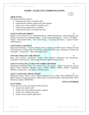
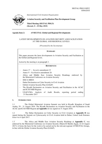
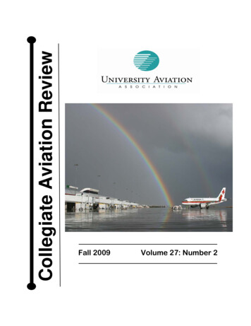
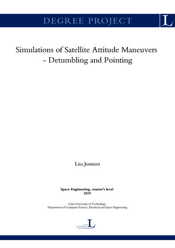
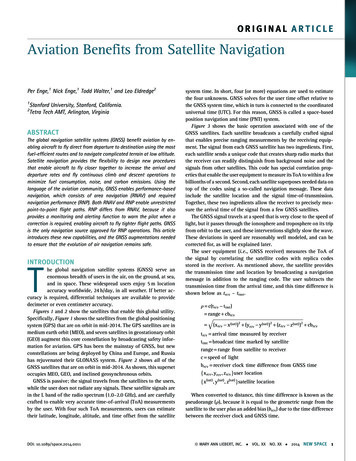
ORIGINAL ARTICLEAviation Benefits from Satellite NavigationPer Enge,1 Nick Enge,1 Todd Walter,1 and Leo Eldredge212Stanford University, Stanford, California.Tetra Tech AMT, Arlington, VirginiaABSTRACTThe global navigation satellite systems (GNSS) benefit aviation by enabling aircraft to fly direct from departure to destination using the mostfuel-efficient routes and to navigate complicated terrain at low altitude.Satellite navigation provides the flexibility to design new proceduresthat enable aircraft to fly closer together to increase the arrival anddeparture rates and fly continuous climb and descent operations tominimize fuel consumption, noise, and carbon emissions. Using thelanguage of the aviation community, GNSS enables performance-basednavigation, which consists of area navigation (RNAV) and requirednavigation performance (RNP). Both RNAV and RNP enable unrestrictedpoint-to-point flight paths. RNP differs from RNAV, because it alsoprovides a monitoring and alerting function to warn the pilot when acorrection is required, enabling aircraft to fly tighter flight paths. GNSSis the only navigation source approved for RNP operations. This articleintroduces these new capabilities, and the GNSS augmentations neededto ensure that the evolution of air navigation remains safe.INTRODUCTIONThe global navigation satellite systems (GNSS) serve anenormous breadth of users in the air, on the ground, at sea,and in space. These widespread users enjoy 5 m locationaccuracy worldwide, 24 h/day, in all weather. If better accuracy is required, differential techniques are available to providedecimeter or even centimeter accuracy.Figures 1 and 2 show the satellites that enable this global utility.Specifically, Figure 1 shows the satellites from the global positioningsystem (GPS) that are on orbit in mid-2014. The GPS satellites are inmedium earth orbit (MEO), and seven satellites in geostationary orbit(GEO) augment this core constellation by broadcasting safety information for aviation. GPS has been the mainstay of GNSS, but newconstellations are being deployed by China and Europe, and Russiahas rejuvenated their GLONASS system. Figure 2 shows all of theGNSS satellites that are on orbit in mid-2014. As shown, this supersetoccupies MEO, GEO, and inclined geosynchronous orbits.GNSS is passive; the signal travels from the satellites to the users,while the user does not radiate any signals. These satellite signals arein the L band of the radio spectrum (1.0–2.0 GHz), and are carefullycrafted to enable very accurate time-of-arrival (ToA) measurementsby the user. With four such ToA measurements, users can estimatetheir latitude, longitude, altitude, and time offset from the satelliteDOI: 10.1089/space.2014.0011system time. In short, four (or more) equations are used to estimatethe four unknowns. GNSS solves for the user time offset relative tothe GNSS system time, which in turn is connected to the coordinateduniversal time (UTC). For this reason, GNSS is called a space-basedposition navigation and time (PNT) system.Figure 3 shows the basic operation associated with one of theGNSS satellites. Each satellite broadcasts a carefully crafted signalthat enables precise ranging measurements by the receiving equipment. The signal from each GNSS satellite has two ingredients. First,each satellite sends a unique code that creates sharp radio marks thatthe receiver can readily distinguish from background noise and thesignals from other satellites. This code has special correlation properties that enable the user equipment to measure its ToA to within a fewbillionths of a second. Second, each satellite superposes needed data ontop of the codes using a so-called navigation message. These datainclude the satellite location and the signal time-of-transmission.Together, these two ingredients allow the receiver to precisely measure the arrival time of the signal from a few GNSS satellites.The GNSS signal travels at a speed that is very close to the speed oflight, but it passes through the ionosphere and troposphere on its tripfrom orbit to the user, and these interventions slightly slow the wave.These deviations in speed are reasonably well modeled, and can becorrected for, as will be explained later.The user equipment (i.e., GNSS receiver) measures the ToA ofthe signal by correlating the satellite codes with replica codesstored in the receiver. As mentioned above, the satellite providesthe transmission time and location by broadcasting a navigationmessage in addition to the ranging code. The user subtracts thetransmission time from the arrival time, and this time difference isshown below as trcv – ttmt.q c(trcv - ttmt ) range ��ffi (xrcv - x(sat) )2 (yrcv - y(sat) )2 (zrcv - z(sat) )2 cbrcvtrcv arrival time measured by receiverttmt broadcast time marked by satelliterange range from satellite to receiverc speed of lightbrcv receiver clock time difference from GNSS timefxrcv , yrcv , zrcv guser locationfx(sat) , y(sat) , z(sat) gsatellite locationWhen converted to distance, this time difference is known as thepseudorange (q), because it is equal to the geometric range from thesatellite to the user plus an added bias (brcv) due to the time differencebetween the receiver clock and GNSS time.ª MARY ANN LIEBERT, INC. VOL. XXNO. XX 2014 NEW SPACE1
ENGE ET AL.Fig. 1. Global positioning system (GPS) satellites on orbit in May 2014. Today, GPS has approximately32 satellites in medium earth orbit (MEO). Also shown, seven satellites in geostationary orbit (GEO)augment GPS; they broadcast real-time error bounds to support aviation use. (Courtesy of Tyler Reid)Fig. 2. Global navigation satellite system (GNSS) satellites on orbit in May 2014. This figure includessatellites from GPS, GLONASS (Russia), Beidou (China), Galileo (Europe), Quasi-zenith Satellite System(QZSS, Japan), and the Indian Regional Navigation Satellite System (IRNSS). As shown, these constellations include satellites in MEO, GEO, and inclined geosynchronous orbits. (Courtesy of Tyler Reid)2 NEW SPACE 2014Each pseudorange measurementis sensitive to the receiver location(xrcv, yrcv, zrcv) and receiver clockoffset, brcv. These four quantities(xrcv, yrcv, zrcv, brcv) are known as theestimanda or the user state. The othervariables in this equation are reasonably well known. Recall that thesatellite broadcasts its location aspart of the navigation message. Thus,four such pseudorange measurements are needed for the estimationof the four-dimensional user state.While four satellites are certainlynecessary to estimate the user state,four satellites may not be sufficient.The satellites must have good geometry relative to each other; theymust be spread across the sky andnot bunched together or co-planar.Figure 3 shows the typical performance of a GNSS receiver in2013. A two-dimensional scatterplot characterizes the performance ofthe receiver. The reported locationsare scattered around the origin (0, 0),where the receiver is truly located. Asshown, the errors are generallysmaller than 5 m. As mentioned earlier, and detailed later, differentialnavigation relative to a referencereceiver at a known location canimprove this performance to yielddecimeter or centimeter accuracies.By the way, the N–S orientation ofthe scatter in Figure 3 is specific tothis data set, and not a general feature of satellite navigation.The data set shown in Figure 3 isbased on the GPS, which is presentlythe most-used satellite constellationwithin the GNSS. GPS was originallydeveloped by the U.S. Department ofDefense in the 1970s. At that time, theplanners predicted that GPS wouldserve a total of 40,000 military userswith some ancillary civil use. Today,the civil community has shipped over3 billion GPS receivers. The civiliantail now wags the GPS dog, and thecivil aviation community has alreadybenefited from a growing set of GPSapplications that are directed at
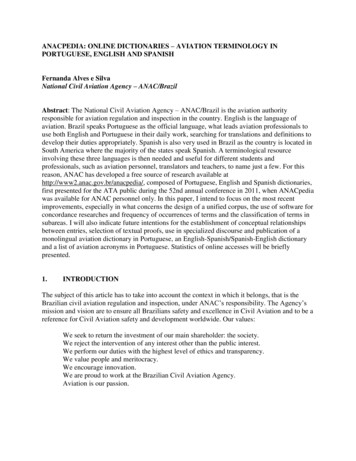
AVIATION BENEFITS FROM SATELLITE NAVIGATIONFig. 3. Basic operation of a GNSS satellite showing the key ingredients of a pseudorange measurement. These include (1) knowntransmission time of a satellite-unique spread-spectrum code, (2) known location of the satellite at the transmission time, (3) knownpropagation speed of the radio wave, and (4) accurate measurement of signal time-of-arrival. The typical accuracy of a GNSS receiver isshown in the scatter plot.increasing efficiency, saving fuel, and reducing the environmentalimpact of aviation.As mentioned earlier, GPS is not alone. Russia has rejuvenatedtheir satellite navigation system, called GLONASS, which has 24satellites as of December 2013. Europe has launched their first prototype satellites for their Galileo system, which will eventually have24 satellites. China is expanding their regional system, BeiDou, toinclude global coverage. Japan and India have also launched satellites for regional systems. Figure 2 depicts the current mélange ofsatellites in this system of systems. In time, these national constellations will comprise a mighty GNSS with over 100 satellites.The multiplicity of satellites described above will provide geometric diversity with signals coming from almost every overheaddirection. Importantly, the new satellites will also provide frequencydiversity for civil users. Each new satellite will radiate civil signalsat three frequencies rather than the single civil frequency offeredbefore 2010.Figure 4 shows the spectrum for the new GNSS signals that arecoming on line in the next 10 years. All of these signals reside inportions of the radio spectrum that have been set aside for radionavigation satellite systems. Some also reside in bands that have beenallocated for aeronautical radio navigation systems (ARNS). Asshown, the GPS satellites broadcast at three civil frequencies calledL1 (1575.42 MHz), L2 (1227.60 MHz), and L5 (1176.45 MHz). L1 ishome to the so-called clear access (C/A) signal; this GPS signal is thebasis for the vast majority of civil applications to date. This C/Asignal overlays military signals in the same band. L2 also carries acivil signal on the seven most recent GPS satellites. L5 is the home forthe third civil signal, and has been included on the four most recentGPS satellites. L5 has a broader spectrum than the civil signals at L1and L2, and so it is the most robust civil signal.1–3Taken together, L1, L2, and L5 provide redundancy to combataccidental radio frequency interference (RFI) and a means to removethe dispersive delay due to the ionosphere. Both features are important. RFI is becoming more prevalent in the GPS bands, and theionosphere is the largest natural source of error. These two challengeswill be further described later in this article. L1 and L5 are particularlyimportant to aviation, because they both fall in ARNS portions of theradio spectrum. Thus, they have greater aviation utility, because theyenjoy greater institutional protection than L2.ª MARY ANN LIEBERT, INC. VOL. XXNO. XX 2014NEW SPACE 3
ENGE ET AL.EFFICIENCY ANDENVIRONMENTAL BENEFITSAs mentioned earlier, satellite navigationwill save aviation fuel and reduce the environmental impact of flight. To tell thistale, we begin by discussing a parallel development: the eco-routing of automobiles.Following this ground-based discussion, weturn our attention to the air. In the subsection titled Juneau, Alaska, and JacksonHole, Wyoming, we discuss the applicationsof GNSS to the departure and approach toairports in mountainous terrain. In thesubsection Optimized Profile Descent, wecontinue our discussion of approach procedures by describing optimized profiledescents (OPDs) that can save fuel and reduce noise pollution. The subsection Tailored Arrivals broadens our interest to theterminal area that surrounds a metropolitanairport (e.g., the New York multiplex or theFig. 4. Signal spectra for GPS, Galileo, BeiDou, and GLONASS. From the left, new GPS San Francisco Bay Area with its three majorsatellites radiate at L5 (1176.45 MHz), L2 (1227.60 MHz), and L1 (1575.42 MHz).airports). The subsection Optimized EnrouteFlight extends our discussion to oceanicThe signals for GLONASS, Galileo, and Compass are also shown inpaths that adapt to weather conditions on a seasonal, daily, or evenFigure 4. As illustrated, they are not located at exactly the samehourly basis.places as the GPS signals. However, they share the main features:triple-frequency diversity with at least two signals in the ARNS bandsEco-Routing for Automobilessurrounding L1 and L5.Recently, Ford and Hyundai, in partnership with TeleNav andAs mentioned earlier, GPS user equipment serves a multitude ofNavtech, have been working to improve the efficiency of automobilesapplications. For example, every new Boeing or Airbus aircraft carby deploying the so-called eco-routing or ‘‘green GPS’’ navigationries a GPS receiver for navigation in the enroute and terminal areasystems in their cars. Like other automotive navigation systems, theseairspace. GPS is also used to guide aircraft while approaching airsystems use distance and average speed to calculate the ‘‘shortest’’ports. In some cases, it provides the most critical vertical dimensionroute and ‘‘fastest’’ route from point A to point B. However, they alsoof location down to altitudes of 200 feet. GPS receivers for aviationconsider additional factors in order to provide the ‘‘greenest’’ or mostare expensive, due to the cost associated with the design and testingfuel-efficient route. Some of these eco-factors arefor such a critical safety application. Stoplights and stop signs: avoid stoppingAt the other cost extreme, most new mobile phones carry GPS/GLO. Traffic: avoid stop-and-go, idling, and very low speedNASS receivers that have a bill of materials around 1. These receivers are. Curves: avoid deceleration and re-accelerationused to guide our walking and driving lives. They also provide our lo. Hills: avoid hill-climbingcation automatically to emergency services when we make such a call.We are now well prepared to engage the body of this article.A study of one such eco-routing navigation system found thatThe Efficiency and Environmental Benefits section focuses on thetaking the greenest route resulted in an average of 10% fuel savings.4efficiency and environmental benefits to aviation from GNSS, deThis estimate is conservative, as these savings are as compared to thescribing four aviation operations where GNSS enables fuel savexisting ‘‘fastest route’’ provided by standard navigation systems,ings. These operations are based on the area navigation (RNAV)which is already significantly more fuel efficient than the averagecapability of GNSS. The section titled Safety focuses on the safety ofroute taken without using a navigation system. Given that highwayair navigation based on GNSS. More specifically, it describes theCO2 emissions account for 26% of the U.S. total from all sources, ecorequired navigation performance (RNP) and discusses the technolrouting for all U.S. road trips has the potential to reduce total U.S. CO2ogy needed to ensure that human-made faults, space weather, andemissions by 2.6%, an impressive impact for such a simple solution.5bad actors (jammers and spoofers) do not endanger aircraft usingBy coincidence, while highway eco-routing has the potential toGNSS for navigation. The Summary section is a brief summary of thissave 2.6% of U.S. CO2 emissions, U.S. aviation accounts for only 2.6%article.of total U.S. CO2 emissions to begin with.5 Even so, aviation will be4 NEW SPACE 2014
AVIATION BENEFITS FROM SATELLITE NAVIGATIONone of the most difficult sectors in which toreduce emissions. This intransigence is dueto aviation’s requirement for fuels with thegreatest energy density (joules/kilogramand joules/volume). Thus, as total emissionsdecline in the future, aviation’s contribution will loom larger. As the relative impactof aviation increases, so will the importanceof finding effective methods of reducing itsgrowing fraction of global CO2 emissions.In the recent history of aviation, innovations in airframe design and propulsionsystems have resulted in significant reductions in aircraft fuel consumption. Between1960 and 2008, the average fuel burn ofnew aircraft decreased by more than half,thanks to improvements in engine efficiency and aerodynamics, and more efficiently utilized capacity.6,7 With the recentintroduction of the Boeing 787, designed tobe 20% more efficient than similar aircraft,Fig. 5. Departures and arrivals from Juneau Airport ( JNU) using the Gastineau Channel. Thethis hopeful trend will continue.8left turn at the far end of the channel, close to the airport, requires an area navigation (RNAV)This article does not further consider capability. Such a path bend cannot be supported with a line-of-sight radio beam from theaerodynamics and propulsion; rather, it ground. (Courtesy of BridgeNet International)focuses on the use of navigation technologytitled Safety, enabled Alaska Airlines to navigate the channel in lowto enable more efficient aircraft routes and procedures. In this secvisibility. Before this capability, aircraft were compelled to avoidtion, we will explore several of these operational improvements, eachJuneau if the weather ceiling was below 1000 feet or the along-trackof which has been enabled by advanced air navigation systems,visibility was less than 2 miles. With GPS-based navigation of theprimarily GNSS. It is important to note, however, that the efficiencyGastineau Channel, the tolerable weather ceiling was dropped to 337improvements due to navigation and those due to airframe designfeet and the along-track visibility shortened to 1 mile.and propulsion are additive.In 1996, Alaska Airlines began to use the Gastineau Channel inearnest. By 2011, Alaska Airlines flew 5,683 arrivals through theJuneau, Alaska, and Jackson Hole, Wyomingnarrow Gastineau Channel with the assistance of GPS navigation. OfAlaska Airlines was the first airline to routinely employ GPSthese flights, 831 were saves, or flights that would have been canceledguidance when approaching airports. Severe weather and landscapeor diverted due to weather if they had not been equipped with GPS.increase the need for navigation when approaching or departingEach year, Alaska Airlines attributes a savings of approximatelyfrom an Alaskan airport. GPS is vital in Alaska, because it provides 1 million to this GPS-based capability in Juneau.navigation signals that surround the entire airport, enabling unreToday, Alaska Airlines uses GPS to support navigation into 30stricted RNAV. RNAV enables aircraft to fly directly between any twoairports in Alaska and in the continental United States. They operate apoints rather than flying the less efficient conventional routes befleet of 117 Boeing 737s equipped with this capability, and their sistertween two radio navigation stations on the ground. For example,airline Horizon Air operates similarly capable Bombardier Q400Alaska Air initiated the use of GPS when flying into the state capital,turboprops. According to Alaska Air, the airline flew 12,700 apJuneau. This city is accessible only by air and water, and the air routesproach and departure procedures in 2011, avoiding the diversion ofrequire several turns and appreciable consideration of safety.1,545 flights through the use of GPS navigation. In that year, theFigure 5 shows a fuel-efficient path for aircraft departing from orairline used GPS to help reduce fuel use by 210,000 gallons and saveapproaching Juneau airport. As shown, this path follows the Gastimore than 15– 19 million across their entire fleet and operations.neau Channel and the aircraft flies northwest to approach Runway 26Jackson Hole, Wyoming, also has a unique airport that benefitsat Juneau airport. Cliffs define both sides of this channel, and thefrom GPS. Figure 6 shows the approach path from above. The airportAlaskan weather frequently blocks the view of these boundaries.( JAC) is located at the bottom left of the figure. As shown, the conFortunately, Alaskan Airlines was able to work with the Federalventional landing route requires two straight line segments based onAviation Administration and The Boeing Company to define the paththe limitations of conventional ground-based radio navigation sysshown in Figure 5. GPS precise positioning with receiver autonomoustems. The first segment flies westward, and the second segment fliesintegrity monitoring (RAIM), which we will discuss in the sectionª MARY ANN LIEBERT, INC. VOL. XX NO. XX 2014NEW SPACE 5
ENGE ET AL.Fig. 6. Arrival to Jackson Hole ( JAC) Airport using GPS-enabledRNAV. The RNAV path is curved and shorter, and avoids the mainattractions of the Grand Teton National Park. (Courtesy ofBridgeNet International)southward to the airport. The new path uses RNAV waypoints for acurved path that avoids the sharp turn and the noise-sensitive areanear Grand Teton National Park. This new path is shorter by 14 milesand 3 min of flight time.Optimized Profile DescentIn the cases of Juneau and Jackson Hole, the approach designersoptimized the horizontal ground track. However, it is also possible tofly more efficient vertical profiles using an OPD, enabling qualifiedaircraft to reduce fuel, noise, and carbon emissions. Currently,standard terminal arrivals use a series of mandatory altitudes alongthe arrival route that gradually step the aircraft down to the airport.The advantage of this step-down design is that it is easy to stan-dardize and minimizes the volume of protected airspace around theairport. In terms of fuel efficiency, time, and noise pollution, however, the step-down approach is not ideal because aircraft use higherpower settings to maintain level flight.An ideal OPD is a continuous descent operation, where the aircraftdescends all the way from cruise altitude to the runway in a smoothglide trajectory using low power, saving time and fuel and reducing noise and emissions (see Fig. 7). Some of these descending aircraft may be idling, while some may need slightly more power toenable anti-icing. These OPDs are published procedures, and so thecontroller can clear the aircraft to fly the OPD. When cleared, anaircraft can descend safely from near-cruise altitude to near therunway, at near-idle thrust.The first OPD flight tests were conducted roughly a decade ago atLouisville International Airport (SDF). The SDF descent resulted inaverage fuel savings of approximately 200 kg per approach of theB737-300 test aircraft. Peak noise levels were also significantly reduced.9In December 2007, Los Angeles International Airport (LAX) implemented the first publicly charted OPD. Across the LAX fleet, eachaircraft using this fully operational OPD saves an average of 25gallons (76 kg) and 200 kg of CO2 emissions per approach. Overall,the OPD at LAX saves approximately 2 million gallons (6 million kg)of fuel each year and reduces annual CO2 emissions by 19 million kg.The OPD also saves time, shaving 44 s off the average flight time, andhas decreased the ground noise around LAX.10Significant fuel savings have been demonstrated in flight trials atother airports as well. For example, OPD flight tests with B757s andB737-800s into Miami International Airport (MIA) showed an average savings of 49 gallons (150 kg) of fuel per approach, and testsof B767s into Hartsfield–Jackson Atlanta International Airport(ATL) demonstrated an average savings of 37 gallons (113 kg) perflight.11OPD savings depend on the efficiency of the OPD trajectory, theinefficiency of the conventional approach, the type of aircraft, andthe weather. At present, the FAA is developing new merging andspacing tools for the controllers to sequence the aircraft on to theOPDs. These improved tools will enable controllers to meter aircrafthundreds of miles away from theaircraft and in the terminal area.Tailored ArrivalsFig. 7. Optimized profile descents (OPD) in contrast to step-down approaches (drive and dive). OPDoffers a close approximation to the optimal idle-thrust glide slope and can save hundreds ofkilograms of fuel per flight. (Courtesy of BridgeNet International)6 NEW SPACE 2014If you have a smartphone or tablet, you may have played FlightControl, the surprisingly addictivegame where the goal is to directplanes to their assigned runwayswhile avoiding potential conflicts. Itstarts out easy, with one plane andthen two, and in these low-trafficconditions, you are free to chooseany path you want. But as the game
AVIATION BENEFITS FROM SATELLITE NAVIGATIONprogresses, and the number of planes on thescreen increases, your choice of flight pathsbecomes much more restricted. If yourstrategy for the game is similar to ours,when the difficulty increases, you end upplaying it safe, creating an orderly queue ofaircraft for each runway, and directing eachnew plane to the back of the line, even if thatmeans tracing out a much longer path thanyou might have otherwise.While the job of real-world air trafficcontrollers requires much more skill thanthis simple game, the basic strategy is similar. When the sky is clear, fuel-efficientflight paths are great. When there is trafficin the sky, avoiding conflicts becomes thenumber one priority, to the detriment of fuel Fig. 8. Tailored arrivals. These aircraft are engaging in advanced terminal arrival procedures.efficiency. Of course, these priorities are Each of the aircraft arriving from the right uses glide slope angles that minimize fuel use forexactly as they should be: safety trumps fuel their aircraft. Also, the aircraft arriving from the left joins the approach pattern shared withthe first three aircraft, which have left an opening in the pattern in anticipation. (Courtesy ofefficiency.BridgeNet International)Unfortunately, this means that the potential benefits of optimized routing oftengo unrealized in real-world circumstances. Fortunately, fuel effiincludes a 30 nm path-stretch at low altitude.12 Traditionally, duringciency and safety need not always be in opposition. Using tailoredheavy traffic, any given flight is looped around to the back of the line.arrivals, we can simultaneously increase fuel efficiency while deTailored arrivals allow the flight to be feathered right into the middlecreasing air traffic controller workload and improving safety.of the queue as the aircraft continues to travel along its own mostTailored arrivals allow for customized arrival pathways for indiefficient approach trajectory. In summary, the SFO trials demonstratevidual flights based on real-time air traffic conditions. The basicthat tailored arrivals can save more fuel in heavy traffic, becauseconcept is this: accurately measure the position and velocity of eachconventional heavy-traffic approaches are often much less efficientaircraft continuously. Use that information, along with real-timethan the low-traffic approaches. (Note: The cited benefits are after aweather data, to accurately predict where each aircraft will be in the25% penalty based on the assumption that in heavy-traffic condifuture. Optimize all of the arrival (and departure) paths together,tions, some upstream path-stretching will still be required to adesimultaneously reducing fuel consumption and flight time for eachquately coordinate arrival times. The actual savings of a truly idealflight while maintaining separation and avoiding conflicts. An exapproach compared to a conventional heavy-traffic approach wouldample is depicted in Figure 8.be 1,896 kg.)Here is how it plays out in practice: the incoming aircraft downIn a later phase of testing at SFO, four airlines testing tailoredlinks its data to air traffic control, which use a computer programarrivals at SFO saved more than 500,000 kg of fuel over the course ofsuch as NASA’s En Route Descent Advisor to generate an optimala year. Tests of tailored arrivals in Melbourne and Sydney found andescent trajectory. This computed trajectory considers the state of theaverage savings of 100–200 kg of fuel per approach, and later trials inaircraft, the predicted trajectories of other aircraft in the airspace, andBrisbane saved 200,000 kg of fuel and 650,000 kg of CO2 emissionsthe weather. This optimal approach pathway is then uplinked to theover the course of a year.13,14aircraft and loaded into the flight management system. While thetechnological capabilities to design and fly these tailored arrivals areOptimized Enroute Flightnot yet widely operational (on the ground or in the air), there haveGNSS also enables advanced procedures for aircraft in enroute orbeen several promising tests of the concept.oceanic flight by considering distance, winds, and convectiveIn 2006, United collaborated with the FAA to test the concept onweather. While eco-routing on the road is limited to choosing the best40 flights from Honolulu to San Francisco (SFO) in various trafficroute using existing highways, eco-routing in the air can go one stepconditions. Under light-traffic conditions, the tailored arrival with anfurther, choosing efficient routes that break free from the traditionalOPD approach into SFO resulted in average fuel savings of 110 kg,highways in the sky. Assisted by GNSS, aircraft can now safely flysimilar to the standard OPD trials described above. Under heavyroutes that deviate from the fixed air traffic service (ATS) routes,traffic conditions, average fuel savings rose to 1,460 kg per approach.realizing significant fuel savings and emissions reductions, whileThis dramatic increase in savings can be explained by the ineffisimultaneously saving time and reducing conflicts. Figure 9 shows aciencies of the conventional heavy-traffic approach into SFO, whichhierarchy of such capabilities.ª MARY ANN LIEBERT, INC. VOL. XX NO. XX 2014NEW SPACE 7
ENGE ET AL.Flexible track systems. The simplest form of optimized routing in thesky is the flexible track system. Operators design and fly an optimizedtrack between a pair o
The Efficiency and Environmental Benefits section focuses on the efficiency and environmental benefits to aviation from GNSS, de-scribing four aviation operations where GNSS enables fuel sav-ings. These operations are based on the area navigation (RNAV) capability of GNSS. The section titled Safety focuses on the safety of air navigation based .