Transcription
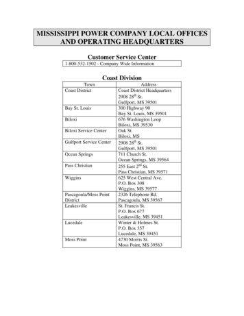
MISSISSIPPI POWER COMPANY LOCAL OFFICESAND OPERATING HEADQUARTERSCustomer Service Center1-800-532-1502 - Company Wide InformationCoast DivisionTownCoast DistrictBay St. LouisBiloxiBiloxi Service CenterGulfport Service CenterOcean SpringsPass ChristianWigginsPascagoula/Moss PointDistrictLeakesvilleLucedaleMoss PointAddressCoast District Headquartersth2908 28 St.Gulfport, MS 39501300 Highway 90Bay St. Louis, MS 39501676 Washington LoopBiloxi, MS 39530Oak St.Biloxi, MS2908 28th St.Gulfport, MS 39501711 Church St.Ocean Springs, MS 39564255 East 2nd St.Pass Christian, MS 39571625 West Central Ave.P.O. Box 308Wiggins, MS 395772326 Telephone Rd.Pascagoula, MS 39567St. Francis St.P.O. Box 677Leakesville, MS 39451Winter & Holmes St.P.O. Box 357Lucedale, MS 394514730 Morris St.Moss Point, MS 39563
Pine Belt DivisionTownPine Belt DistrictHeadquartersHattiesburg OfficeHattiesburg ServiceCenterColumbiaLumbertonPicayunePicayune Laurel Service CenterBay SpringsEllisvilleHeidelbergAddress2601 Highway 11 BypassHattiesburg, MS 39401420 West Pine St.P. O. Box 1271Hattiesburg, MS 394012601 Highway 11 BypassHattiesburg, MS 39401501 Broad St.P. O. Box 208Columbia, MS 39429401 West Main St.Lumberton, MS 39455114 Elizabeth St.Picayune, MS 39466201 West Cumberland St.P. O. Box 351Poplarville, MS 39470135 Front St.Purvis, MS 39475206 South Front St.P.O. BoxRichton, MS 39467Main StreetP.O. Box 248Sumrall, MS 39482411 Oak St.P.O. Box 287Laurel, MS 39440Kingston & Front St.Laurel, MS 39440Bay CenterHighway 15 SouthP. O. Box 367Bay Springs, MS 39422106 Holly St.P.O. Box 580Ellisville, MS 39437Main St.P.O. Drawer GHeidelberg, MS 39439
Taylorsville107 Highway 28, EastP.O. Box 376Taylorsville, MS 39168807 Azalea DriveP.O. Box 872Waynesboro, MS 39369-0872WaynesboroMeridian DivisionTownMeridian DistrictMeridian ServiceCenterForestForest Service CenterNewtonQuitmanStonewallUnionAddress2401 11 St.Meridian, MS 393013118 Highway 45 NorthMeridian, MS 39301rd610 East 3 St.P.O. Box 90Forest, MS 39074th201 Scanlan St.P.O. Box 67Newton, MS 39345304 South Archusa Ave.Quitman, MS 39355Burlington Ave.P.O. Box 68Stonewall, MS 39365313 Bank St.P.O. Box 146Union, MS 39365MPC Metering Services DepartmentTownMetering ServicesAddress3118 Highway 45 NorthMeridian, MS 39301601-484-2654For questions concerning information in this booknot specifically addressed call601-484-2654 or (internal only) 8-760-2654.
INTRODUCTIONThis booklet is issued primarily as a convenient reference for customers, architects, engineers andcontractors planning or constructing buildings or installing, repairing, or renewing apparatus orequipment to be connected to the Company’s distribution system. Any future reference to the Companywill imply Mississippi Power Company unless otherwise stated.The practices discussed have been derived from research, experience and technical consideration. Assuch they are supplementary to and do not intentionally conflict with the National Electrical Codeor state and municipal laws and ordinances that may be in force within the cities, towns, orcommunities in which the Company furnishes electric service. If any conflict exists, the Code, law,or ordinance shall control.It is always necessary to refer to and comply with applicable codes, statutes, utility commission rules,and local ordinances. The information contained herein is general and does not include every detail orevery lawful requirement.The Company desires to serve its customers promptly and satisfactorily. It will endeavor to cooperatewith contractors and customers to the fullest extent in completing service connections with as little delayand inconvenience as possible and will gladly give special attention to any particularly difficult situationconfronting a customer.The Company will be pleased to confer with those desiring information concerning rates, services, etc.,upon request.DEFINITIONSGeneral InformationAlterations and AdditionsApplication For Service:Availability and Classification of Service:Number of Services and Meters:Use of Service by the Customer:Temporary Service:Extensions:Motor Requirements:Power Factor Correction:Capacitor Installation:Cogeneration:Service Quality:Liability for Service Interruption:Overhead Services:Underground Services:Customer Owned Sockets:Transformer Vaults:Grounding:Tampering and Sealing:Page 1
DEFINITIONSAmpere Rating - The maximum allowable current that can safely pass through a device.Approved - Acceptable to a qualified Mississippi Power Company employee.Class of Service - The voltage rating and the number of phases for a particular service.Company - Mississippi Power Company.Conduit - A tubing or duct in which electric wires or cables are enclosed.Current Transformer (CT) - A device which reduces the load current by a known ratio for meteringpurposes.CT Enclosure (Instrument Transformer Enclosure) - A metal cabinet which houses instrumenttransformers.CT Socket (Instrument Transformer Rated Source) - A meter socket that is used only withinstrument transformers.Customer - The corporation, municipality, governmental agency, association, partnership or individualusing or planning to use electric service supplied by the Company or the architect, engineer, or electricalcontractor acting as the customer’s agent.Diversified Demand - A company calculation to determine the maximum anticipated load (kw) basedupon the customer’s usage patterns and operation.Electric Service - Electrical energy that is made available to the customer at the point of delivery.Energy - The measure of work done. The electrical unit of energy is the kilowatt-hour, which is 1,000watt-hours.Final Grade - Ground level after all construction and landscaping procedures have been completed.Grounded Conductor - A system or circuit conductor that is intentionally grounded.Grounding Conductor, Equipment - The conductor used to connect non-current carrying metal partsof equipment, raceways, and other enclosures to the system grounded conductor and/or the groundingelectrode conductor at the service equipment or at the source of a separately derived system.Grounding Electrode Conductor - The conductor used to connect the grounding electrode to theequipment grounding conductor and/or to the grounding conductor of the circuit at the serviceequipment or at the source of a separately derived system.Instrument Transformer - A current transformer or potential transformer used in metering.Page 2
Instrument Transformer Enclosure (CT Enclosure) - A metal cabinet which houses instrumenttransformers.Isolated Location - Not readily accessible to persons unless special means for access are used.Listed Equipment- Equipment or materials included in a list published by an organization acceptable tothe authority having jurisdiction and concerned with product evaluation. This organization maintainsperiodic inspection of material or devices and finds them suitable for use in a specified manner.i.e. Underwriters Laboratory (U.L.)Maximum Available Fault Current - The maximum amount of current that can flow when a fault(short circuit) condition exists between a conductor and ground or between two or more conductors at agiven location.Meter - A device that measures the amount of power and/or energy delivered to a customer.Meter Socket - A weatherproof receptacle used for mounting a socket type meter.National Electric Code (NEC) - The National Electrical Code, ANSI/NFPA 70. The code whichgoverns the installation of electric conductors and equipment within or on public or private buildings orother structures. At the time of this printing, the current revision of the code is the 1993 edition. Futurerevisions of the National Electrical Code may change the requirements of the code or the referencescontained herein.National Electrical Safety Code (NESC) - The National Electrical Safety Code, ANSI C2-1993. Thecode which governs the installation, operation, and maintenance of electric supply and communicationlines, equipment, and associated work practices employed by utilities. Future revisions of the NationalElectrical Safety Code may change the requirements of the code or the references contained herein.Neutral - The grounded service which carries the unbalanced 60 hertz current from other conductors.Point of Delivery - The point at which the customer’s conductors are connected to the Company’sconductors.Potential Transformer (PT) - A device which reduces the service voltage by a known ratio formetering.Power (Demand) - The average rate of energy used over a period of time. A 15 minute interval is usedfor billing purposes. The unit of measure for power is the Kilowatt (kW), which is 1000 watts.Qualified Employee - A Mississippi Power Company employee familiar with company safety rules andregulations and the construction, application, and operation of the equipment involved.Raceway - An enclosed channel designed expressly for holding wires, cables, or bus bars.Readily Accessible - Capable of being reached quickly, for operation, renewal, or inspections withoutrequiring those to whom ready access is requisite to climb over or remove obstacles or to resort toportable ladders, chairs, etc.Page 3
Service - The conductors and equipment for delivering energy from the electricity supply system to thewiring system of the premises served.Service Drop - The overhead service conductors that extend from the Company’s last pole or aerialsupport to and including the splices, if any, connecting the customer’s service entrance conductors at thebuilding or other structure.Service Entrance - The customer’s conductors, conduit, and other associated equipment which extendsfrom the point of delivery to the service equipment.Service Entrance Capacity - The maximum rated allowable current passing through the serviceequipment.Service Entrance Conductors: Overhead System - The service conductors between the terminals ofthe service equipment and a point usually outside the building, clear of building walls, where they arejoined by tap or splice to the service drop.Service Entrance Conductors: Underground System - The service conductors between the terminalsof the service equipment and the point of connection to the service lateral.Service Equipment - The necessary equipment, usually consisting of a circuit breaker or switch andfuses, and their accessories located near the point of entrance of supply conductors to a building or otherstructure, and intended to be the main electrical supply disconnect.Service Lateral - The underground service conductors between the Company’s distribution system andthe point of delivery including any risers at a pole or transformer.Special Permission - The written consent of the Company.Weatherproof - So constructed or protected that exposure to weather will not interfere with successfuloperation.GENERAL INFORMATIONA. Alterations and Additions:When the Company connects a customer’s installations to its supply lines, arrangements are made formeters, transformers, and other equipment to fit the installations as it is at that time. For maximumsafety and billing accuracy, it is essential that the customer or contractor give notice to the Companybefore making any changes which will significantly increase or decrease the electrical load, reduceconductor clearances, or enclose or restrict access to Company facilities.Page 4
B. Application For Service:The Company maintains local offices strategically placed throughout its service area as well as acompany-wide customer service center. Information concerning original or added service should bedirected to the Customer Service Center by calling 1-800-532-1502 or local offices.The customer shall provide, free of expense to the Company, suitable locations and space for thetransformer(s), meters, and other equipment owned by the Company which are necessary to supplyservice.An application for service will be considered permission to cross the customer’s property and install anyequipment which may be necessary to provide electric service.To avoid unnecessary delays, applications for service should be made as far in advance of requiredservice date as possible. Specific instructions for locating the service address, will help to assure promptservice.C. Availability and Classification of Service:The customer should consult the Company well in advance of the date that service is required in order todetermine what type of service is available in a particular location. A qualified company employee willdetermine the voltage, phase, etc. of a particular service since the availability may vary betweendifferent locations.The information contained in this booklet refers primarily to service requirements at secondarydistribution voltages (under 600 volts) for light and power installations. Service requirements forinstallations requiring higher distribution voltages are subject to special negotiations between thecustomer and the Company.The Company is available to advise customers concerning the use of electrical equipment or situationsnot covered in this book.D. Number of Services and Meters:The Company shall connect only one service drop or service lateral to a building or structure for eachclass of service except as permitted by Section 230-2 of the National Electrical Code.Only one watt-hour meter shall be installed per customer per class of service. An exception will bemade if the characteristics of the customer load or billing rate require the Company to utilize multiplemeters. Multiple meters will not be used for the customer’s benefit.On installations comprising more than six meters, a sealable main disconnect or main breaker, of a typeacceptable to the Company, shall be provided as required by the National Electrical Code. Thecustomer will always provide and maintain any main breakers or disconnectsPage 5
E. Use of Service by the Customer:Compatibility between the Company’s distribution system and the customer’s wiring system is ofutmost importance. Because of this the following operating procedures are recommended to thecustomer: To safeguard both the property of the customer and that of the Company, the customer is warnedagainst overfusing either the main fuse or those on branch circuits by installing fuses or circuitbreakers larger than approved by the National Electrical Code, or in any way making protectivedevices of any type inoperative. The customer’s wiring and equipment should be maintained in the condition required byinspection authorities having jurisdiction. The customer should use equipment and service insuch a manner as not to disturb the company’s service to other customers. When designing a wiring system, the customer should balance the load connected across eachphase of the system as nearly as practical. The customer’s wiring and equipment is to be installed and maintained by the customer in thecondition required by the NEC or governmental authorities having jurisdiction. Customer equipment must not introduce electric or magnetic interference on the Company’ssystem. Control devices such as those used for lighting and motor control shall be of such design as tointroduce a minimum of harmonic distortion or other disturbances into the Company’s system.These are detailed on page 11. The customer shall not use electric energy from any other source while being supplied by theCompany without written consent of the Company. Electric service supplied to a customer shall not be resold or shared with others. Anestablishment which supplies electricity purchased from the Company to its tenants without anyspecific energy charges will not be considered as sharing with others.F. Temporary Service:Application for temporary service should be made well in advance of the required service date. Toinsure prompt service, the location of the temporary service should be plainly marked with the lotnumber and/or street address as shown on the service application.G. Extensions:In order to avoid delay, persons desiring service beyond the existing electric distribution lines of theCompany should consult with the Company for the conditions under which service may be provided,and make the necessary arrangements before wiring installations are started.Page 6
H. Motor Requirements:The following requirements and suggestions apply to motors connected to the secondary distributionsystems of the Company: The National Electrical Code requires that all motors be equipped with suitable starting switchesand have overload protection. The use of automatic time-delay circuit breakers for circuit protection in all cases is stronglyrecommended and where fuses are used they should be of the time-delay type. This time delaywill, in many instances, prevent unnecessary shut-downs due to the tripping of an instantaneoustype circuit breaker or blowing of ordinary short time fuses by large currents resulting frommotor starting, temporary overloads or temporary low voltage conditions and ordinarily willprovide adequate protection. All automatic controls using the time delay should be coordinated. In general, 120 volts single phase motors may be connected to a 2 wire, single phase service,provided the locked rotor current does not exceed 50 amperes. Motors in excess of 50 amperesmay be connected to a 240 volt, 3 wire service, provided the locked rotor current does not exceed150 amperes. Any applications of single phase motors exceeding these requirements are to bereferred to the Company. All single phase motors should be connected for 240 volts whenever it is practical to do so inorder to minimize voltage drop in the customer’s wiring system and the supply system. Before any polyphase motors are installed it is advisable that the Company be consulted in orderto determine the type and adequacy of the available service. Where three phase service has beensecured, polyphase motors over 50 horsepower shall not be connected without utility startingequipment or other suitable technologies that limit starting current.I. Power Factor Correction:It is important to maintain the power factor of any load as near unity as possible. The maintenance of ahigh power factor may result in the reduction of conductor losses and equipment capacity requirementsas well as higher overall efficiency.J. Capacitor Installation:In general, capacitors must be applied more carefully than most types of electrical equipment in orderthat satisfactory operation and maintenance will result. The customer should confer with the Companybefore any installations of this type of equipment are made.Page 7
K. Cogeneration:Improperly installed generation equipment can create serious hazards to Company personnel working onthe distribution system as well as for other customers connected to the distribution system. Theoperation of improperly installed generators can also result in damage to customer’s wiring, electricalequipment or the generator itself. To safeguard against these hazards, customer owned generators shallbe installed as follows: Standby generators shall be installed in compliance with the National Electrical Code and localcodes. Customers utilizing emergency or standby generators shall provide an adequatelysized double throw switch which will open all ungrounded conductors from the normalsupply before connection is made to the emergency supply, and vice versa. Power from astandby generator must never be supplied to another premise because of the danger created byback-feeding into the distribution system. Subject to special requirements the Company will allow customer operation of parallelgenerating facilities. Generators designed to run parallel with the Company’s system requirespecial protective devices and operation coordination. Cogeneration is not allowed unless theCompany is consulted prior to the installation and operation of parallel generators. Please consultthe Company for specific requirements. A written agreement must be executed beforeinterconnection. The customer may install an uninterruptible power supply on his system. An automatic transferswitch must be provided by the customer to disconnect the normal supply in the event of a poweroutage.L. Service Quality:The integrity of electric service is of utmost concern to the Company. Normal system operations andunavoidable system disturbance may, however, cause customers to experience problems with certaintypes of equipment, most notably computers. If the customer should experience equipmentmalfunctions caused by system disturbances, the Company stands ready to advise and assist thecustomer in resolving these problems. Please contact a qualified employee.M. Liability for Service Interruption:The Company will, at all times, exert itself toward the goal of supplying as nearly constant service as isreasonably practicable. However the Company does not and cannot not guarantee the supply of electricenergy will be free from temporary interruptions. Temporary interruptions of the Company’s serviceshall not constitute a breach of the Company’s service obligations.The Company is not liable for any damage which the customer may sustain by reason of the failure orpartial failure of the service, or failure or reversal of phases, or variation in service characteristics,whether caused by accident, variation in service characteristics, repairs or other causes; nor is theCompany liable for damage that may be incurred by the use of any service wiring, connections,instruments, services or electrical appliances, installed by or for the customer; nor is the Company liablefor damage that may be incurred due to the presence of the Company’s property on customer’s premises.Page 8
In the event of interruptions of service, the Company will restore the service as soon as reasonablypractical. In the event conditions on the customer’s premises cause an interruption, the Company willallow a reasonable time for those conditions to be corrected, but reserves the right to disconnect theservice until the conditions are corrected to preserve the safety and reliability of the Company’s system.If the customer requires three phase service, the installation and maintenance of adequate relays withcircuit breakers to protect against single phase conditions and phase reversal are advisable. Theirinstallation and maintenance is the responsibility of the customer.N. Overhead Services:To avoid unnecessary delays, the availability of types of service should be confirmed with the Companybefore construction begins.The point of connection between the Company’s service drop and the customer’s wiring system shouldbe located at a point convenient to both the Company and the customer. Normally, the point ofconnection for an overhead secondary service is at the drip loop where the service is attached to thecustomer’s structure. To comply with the appropriate safety codes, the point of connection must provideservice drop clearances from windows, doors, awning or other parts of the building not less than thoserequired in the current NEC. However, the service drop point of attachment shall not exceed 30 feetabove final ground level.The service drop will be attached to the customer’s building at the point of connection only. Multiplepoints of attachments such as the service drop being attached to a corner of the building and thenrunning to the point of connection will not be allowed.If the type of building will not permit these minimum clearances, some satisfactory form of service mastmust be provided to obtain them. The recommended structure for this purpose is a galvanized servicemast through the roof. This mast shall have minimum strength equal to that of 2 inch inside diameterrigid steel conduit and shall extend above the roof the distance required by the National Electrical Codeto give adequate clearance for overhead service conductors. Where long service drops are required, alarger size conduit may be necessary. The service mast shall be sufficiently braced to support theservice conductors and shall be located at a point on the building where the service conductors from thepole will not overhang the roof, except for the overhanging eaves. The service mast must be secured byretaining straps placed no further apart than 24 inches. A minimum of two straps is required. There areto be no joints in the conduit above the straps. The portion of the service drop passing over the roof,including overhanging eaves, shall not exceed four feet. The clearance between the service drop androof shall not be less than 18 inches at any point.Safe and adequate anchorage structures for the Company’s service drop and/or connections are requiredof the customer and in no case will the Company be responsible for the conditions of any customer’sbuildings or structures to which service wires are attached or have been attached.Where service wires are to be installed on the side of buildings which have stucco, hollow tile, stone,brick, brick veneer, plaster, or sheet metal walls, and where there is available no surface suitable for theattachment of service supports having a screw fastening (house knob), the customer will install asuitable anchorage bolt or spool rack. Where the load to be served is sufficiently large to require the useof overhead service conductors of No. 4/0 aluminum and larger, 5/8” galvanized bolts for spoolracks or5/8” eye bolts are required. Where the service conductors are smaller than No. 4/0 aluminum, the boltsmay be smaller than 5/8 inch but in no case smaller than 3/8 inch diameter. These bolts are to be spacedPage 9
to conform to the conductor spacing as specified by the Company and should extend through the walland each be anchored on the inside surface with a substantial washer not less than 1/8 inch thick and twoinches square.To prevent moisture from entering the raceways of conduit for service entrance conductors or serviceentrance cable, it is advisable to terminate them on the outside building wall at a point approximately 6inches above the point of attachment of the highest service drop wire. The individual service entranceconductors are to extend downward to the points where connections are made to the service drop wiresto form a drip loop. Each conductor of the service entrance must extend not less than TWO FEETbeyond the service head to allow adequate wire for the drip loop and connection.O. Underground Services:The availability of underground service should be confirmed with the Company before constructionbegins.Point of Service/ LocationThe point of connection between the Company’s service lateral and the customer’s service entranceconductors shall be determined by a qualified employee after consultation with the customerPadmounted transformers shall normally be located a minimum of 10 feet from a building. Clearancecan be reduced (consistent with the applicable Code) if approved by the Company and the localinspection authority. Padmounted transformer locations are to be readily accessible and free fromobstructions. They shall also be located where adequate natural airflow occurs preventing excessivetransformer heating. The Company will make a final determination of the locations adequacy.Locations are to be approved by the Company prior to construction.In certain prescribed districts or streets in downtown areas where the Company maintains anunderground distribution system, underground services are installed by the customer at the customer’sexpense from an underground connection point generally in a company-provided hand hole, man hole,or vault at or near the property line of the customer. The Company will extend its service conductorsnot more than five feet inside the property line to these junction points.When an instrument transformer enclosure is used, the point of connection (demarcation) shall be in thisenclosure.Service laterals, conduits, and accessories shall be furnished and installed by the customer and shallremain the property of the customer. The final connection of customer service entrance conductors willbe made at the transformer by the Company. Company metering shall be located at one level only,preferably at the ground floor or basement level.Generally, if the commercial/industrial customer is served from a padmounted transformer which isdedicated to that customer only, the point of connection will be at the secondary terminals of thepadmounted transformer. MPC will furnish secondary connectors and install conductors at thepadmount provided the provisions concerning maximum number of conductors per phase on page 13 aremade. Consult the Company for specific details.Page 10
Special company policies cover residential underground services. Please consult the Company forspecific requirements. The Company will install, own, and maintain service lateral conductors to theservice location on the outside wall of the residence. This point should be the closest point to theCompany’s distribution facilities.Each socket and service equipment in a group must be plainly and permanently marked to designate theparticular suites, offices, or apartments served.Conduit/Conductors/RacewaysAll conduit and direct buried conductors shall be buried at a depth of not less than 30 inches below finalgrade.Service voltage supplied from single phase pad-mounted transformers will be 120/240 volts.Services from three phase padmounted transformers shall be either 120/208 volts or 277/480 volts asdetermined by the Company.Metering equipment shall not be mounted in or on single phase, padmount transformers. Conduit must be securely fastened to the wall within 12 inches of the meter socket and 6 inchesof final grade level. Conduit straps shall be fastened to walls with the same type fasteners asmeter sockets. Inhibitor of the non-grit type must be applied to conductors when aluminum conductors are used. Safety dictates all meter positions shall be properly covered before the meter socket is energized. The service entrance conductors must be run in sealable meta
MISSISSIPPI POWER COMPANY LOCAL OFFICES AND OPERATING HEADQUARTERS Customer Service Center 1-800-532-1502 - Company Wide Information Coast Division . Hattiesburg, MS 39401 Hattiesburg Office 420 West Pine St. P. O. Box 1271 Hattiesburg, MS 39401 Hattiesburg Service Center 2601 Highway 11 Bypass