Transcription
SPR-2800xSPR-3300xSPR-4000xSPR-5000xOwner’s ManualSunPower SolarInverter
SunPower Solar InverterOwner’s Manual
TrademarksSunPower Solar Inverter is a trademark of SunPower Corporation.Other trademarks, registered trademarks, and product names are the property of their respective owners and are usedherein for identification purposes only.Notice of CopyrightSunPower Solar Inverter Owner’s Manual May 2007. All rights reserved.DisclaimerUNLESS SPECIFICALLY AGREED TO IN WRITING, SunPower Corporation:(a) MAKES NO WARRANTY AS TO THE ACCURACY, SUFFICIENCY OR SUITABILITY OF ANYTECHNICAL OR OTHER INFORMATION PROVIDED IN ITS MANUALS OR OTHER DOCUMENTATION.(b) ASSUMES NO RESPONSIBILITY OR LIABILITY FOR LOSS OR DAMAGE, WHETHER DIRECT,INDIRECT, CONSEQUENTIAL OR INCIDENTAL, WHICH MIGHT ARISE OUT OF THE USE OF SUCHINFORMATION. THE USE OF ANY SUCH INFORMATION WILL BE ENTIRELY AT THE USER’S RISK.Date and RevisionMay 2007 Revision BManual Part Number975-0335-01-01SunPower Document Number001-11872 Rev *BProduct Part Number864-1012 (SPR-2800x), 864-1013 (SPR-3300x), 864-1014 (SPR-4000x), 864-1015 (SPR-5000x)Contact InformationTelephone:Fax:Email:Web:1 877 SUN 0123(408) 877 om
About This ManualThis Owner’s Manual provides explanations and procedures for installing,operating, maintaining, and troubleshooting the SunPower Solar Inverter .ScopeThe manual provides safety guidelines, detailed planning and setup information. Itprovides procedures for installing the inverter and information about operatingand troubleshooting the unit. It does not provide details about particular brands ofphotovoltaic (PV) panels. You need to consult individual PV manufacturers forthis information.AudienceThis manual does not provide sufficient information for anyone but a qualifiedinstaller to install this product. Installers should be electricians or technicians fullyeducated on the hazards of installing electrical equipment. The monitoring andoperation information in this manual is intended for anyone who needs to operatea SunPower Inverter.OrganizationThis manual is organized into 6 chapters and an appendix.Chapter 1 contains information about the features and functions of the SunPowerSolar Inverter.Chapter 2 provides information about installing the SunPower Solar Inverter. Itcontains information on determining a suitable location for installation, PV arrayrequirements, and procedures for mounting the unit.Chapter 3 provides information about DC and AC wiring, and grounding theSunPower Solar Inverter and the PV array.Chapter 4 contains information on starting up the SunPower Solar Inverter andperforming a functional test.Chapter 5 contains information for understanding the LCD screens and the LEDindicators.Chapter 6 contains information about how to provide general maintenance for theSunPower Solar Inverter. It also provides information about troubleshooting theunit.Appendix A contains information about the specifications of the SunPower SolarInverter.975-0335-01-01iii
About This ManualConventions UsedThe following conventions are used in this guide.WARNINGWarnings identify conditions that could result in personal injury or loss of life.CAUTIONCautions identify conditions or practices that could result in damage to the unit or otherequipment.Important: These notes describe things which are important for you to know, but notas serious as a caution or warning.Abbreviations and cVMPPCalifornia Energy CommissionCanadian Standards AssociationGround Fault Detector/InterrupterLiquid Crystal DisplayLight Emitting DiodeMaximum Power Point TrackingUS National Electrical Code NFPA-70PhotovoltaicPV Ground Fault ProtectionStandard Test ConditionUnderwriters LaboratoriesVolts ACVolts DCVoltage at Maximum PowerVOCOpen Circuit Voltage975-0335-01-01
About This ManualSymbols Used Ground In this guide: Important information, warnings, or cautions.On the product: Important information, warnings or cautions with furtherexplanation in the product guide. Caution, risk of electric shock. Hot surface—risk of burns.Refer to the operating instructions.Related InformationYou can find more information about SunPower Corporation atwww.sunpowercorp.com.975-0335-01-01v
vi
Important Safety InstructionsSAVE THESE INSTRUCTIONS—This manual contains important instructions that must be followedduring the installation and maintenance of the SunPower Solar Inverter.WARNINGThe following warnings identify conditions or practices that could result in personal injury or loss of life.1. Before installing and using the inverter, read all instructions and cautionary markings on the inverter,wiring box, and all appropriate sections of this guide.2. To reduce risk of fire hazard, do not cover or obstruct the heat sink.3. Under some conditions, the inverter heat sink can reach temperatures hot enough to cause skin burns ifaccidentally touched. Ensure that the inverter is located away from normal traffic areas.4. Use only accessories recommended or sold by the manufacturer. Doing otherwise may result in a riskof fire, electric shock, or injury to persons.5. To avoid a risk of fire and electric shock, make sure that existing wiring is in good condition and thatwire is not undersized. Do not operate the inverter with damaged or substandard wiring.6. Do not operate the inverter if it has received a sharp blow, been dropped, or otherwise damaged in anyway. If the inverter is damaged, consult your product warranty.7. Do not disassemble the inverter. It contains no user-serviceable parts. See warranty for instructions onobtaining service. Attempting to service the inverter yourself may result in a risk of electrical shock orfire and will void the factory warranty.8. Authorized service personnel should reduce the risk of electrical shock by disconnecting both AC andDC power from the inverter before attempting any maintenance or cleaning or working on any circuitsconnected to the inverter. Turning off controls will not reduce this risk. Internal capacitors remaincharged for 5 minutes after disconnecting all sources of power.9. Normally grounded conductors may be ungrounded and energized when a ground fault is indicated.10. The inverter must be connected to an AC equipment-grounding conductor directly and a DCgrounding electrode conductor to a single point ground.11. The AC Neutral connection is for voltage sensing only and is not used as a current carrying conductor,nor is it bonded to ground.CAUTIONThe following caution identifies conditions or practices that could result in damage to the unit or otherequipment.Observe the clearance recommendations as described on page 2–7. Do not install the inverter in a zeroclearance or non-ventilated compartment. Overheating may result.975-0335-01-01vii
SafetyLocation of Safety and Data LabelsThe figure below shows the location of the safety label and the data label with model, serial number andpart number information.Data LabelSafety LabelFCC Information to the UserThis equipment has been tested and found to comply with the limits for a Class B digital device, pursuantto part 15 of the FCC Rules. These limits are designed to provide reasonable protection against harmfulinterference in a residential installation. This equipment generates, uses and can radiate radio frequencyenergy and, if not installed and used in accordance with the instructions, may cause harmful interference toradio communications. However, there is no guarantee that interference will not occur in a particularinstallation. If this equipment does cause harmful interference to radio or television reception, which canbe determined by turning the equipment off and on, the user is encouraged to try to correct the interferenceby one or more of the following measures: viiiReorient or relocate the receiving antenna.Increase the separation between the equipment and the receiver.Connect the equipment into an outlet on a circuit different from that to which the receiver is connected.Consult the dealer or an experienced radio/TV technician for help.975-0335-01-01
ContentsImportant Safety Instructions - - - - - - - - - - - - - - - - - - - - - - - - - - - - - - - - viiLocation of Safety and Data Labels - - - - - - - - - - - - - - - - - - - - - - - - - - - - - - - - - - - - - - - - - - viiiFCC Information to the User - - - - - - - - - - - - - - - - - - - - - - - - - - - - - - - - - - - - - - - - - - - - - - - viii1 IntroductionAbout the SunPower Solar Inverter - - - - - - - - - - - - - - - - - - - - - - - - - - - - - - - - - - - - - - - - - 1–1Standard Features - - - - - - - - - - - - - - - - - - - - - - - - - - - - - - - - - - - - - - - - - - - - - - - - - - - - 1–2Front Panel Features - - - - - - - - - - - - - - - - - - - - - - - - - - - - - - - - - - - - - - - - - - - - - - - - - - 1–3Wiring/Disconnect Box - - - - - - - - - - - - - - - - - - - - - - - - - - - - - - - - - - - - - - - - - - - - - - - - 1–32 InstallationInstallation Options - - - - - - - - - - - - - - - - - - - - - - - - - - - - - - - - - - - - - - - - - - - - - - - - - - - - 2–1Planning the Installation - - - - - - - - - - - - - - - - - - - - - - - - - - - - - - - - - - - - - - - - - - - - - - - - - 2–1Inverter Location - - - - - - - - - - - - - - - - - - - - - - - - - - - - - - - - - - - - - - - - - - - - - - - - - - - - 2–1PV Array Voltage and MPPT Requirements - - - - - - - - - - - - - - - - - - - - - - - - - - - - - - - - - - 2–3Mounting the Inverter - - - - - - - - - - - - - - - - - - - - - - - - - - - - - - - - - - - - - - - - - - - - - - - - - - 2–5Dimensions and Knockout Locations - - - - - - - - - - - - - - - - - - - - - - - - - - - - - - - - - - - - - - 2–5Installing the Mounting Bracket - - - - - - - - - - - - - - - - - - - - - - - - - - - - - - - - - - - - - - - - - - 2–6Mounting the Inverter on the Bracket - - - - - - - - - - - - - - - - - - - - - - - - - - - - - - - - - - - - - - 2–83 Wiring the InverterGrounding Requirements - - - - - - - - - - - - - - - - - - - - - - - - - - - - - - - - - - - - - - - - - - - - - - - - 3–1Ground Fault Fuse - - - - - - - - - - - - - - - - - - - - - - - - - - - - - - - - - - - - - - - - - - - - - - - - - - - 3–3Wiring Requirements - - - - - - - - - - - - - - - - - - - - - - - - - - - - - - - - - - - - - - - - - - - - - - - - - - - 3–4AC Circuit Breaker Requirements - - - - - - - - - - - - - - - - - - - - - - - - - - - - - - - - - - - - - - - - - 3–4DC/AC Disconnect Switch - - - - - - - - - - - - - - - - - - - - - - - - - - - - - - - - - - - - - - - - - - - - - 3–4Accessing the Wiring Terminals - - - - - - - - - - - - - - - - - - - - - - - - - - - - - - - - - - - - - - - - - - - 3–5Connecting the DC Wiring - - - - - - - - - - - - - - - - - - - - - - - - - - - - - - - - - - - - - - - - - - - - - - - 3–7DC Wiring for Multiple Inverters - - - - - - - - - - - - - - - - - - - - - - - - - - - - - - - - - - - - - - - - - 3–9Connecting the AC Wiring - - - - - - - - - - - - - - - - - - - - - - - - - - - - - - - - - - - - - - - - - - - - - - - 3–10DC and AC Wiring for Multiple Inverters - - - - - - - - - - - - - - - - - - - - - - - - - - - - - - - - - - - - - 3–11Communications Wiring for Multiple Inverters - - - - - - - - - - - - - - - - - - - - - - - - - - - - - - - - - 3–12Network Layout - - - - - - - - - - - - - - - - - - - - - - - - - - - - - - - - - - - - - - - - - - - - - - - - - - - - 3–12Guidelines for Routing the Network Cables - - - - - - - - - - - - - - - - - - - - - - - - - - - - - - - - - 3–15Connecting Network Cable Between Multiple Inverters - - - - - - - - - - - - - - - - - - - - - - - - - 3–15975-0335-01-01ix
Contents4 Starting the InverterStartup Procedure - - - - - - - - - - - - - - - - - - - - - - - - - - - - - - - - - - - - - - - - - - - - - - - - - - - - - Checking the PV Array DC Voltage - - - - - - - - - - - - - - - - - - - - - - - - - - - - - - - - - - - - - - Checking the AC Utility Voltage - - - - - - - - - - - - - - - - - - - - - - - - - - - - - - - - - - - - - - - - Replacing the Wiring/Disconnect Box Cover - - - - - - - - - - - - - - - - - - - - - - - - - - - - - - - - Starting up the Inverter - - - - - - - - - - - - - - - - - - - - - - - - - - - - - - - - - - - - - - - - - - - - - - Commissioning Multiple Inverters - - - - - - - - - - - - - - - - - - - - - - - - - - - - - - - - - - - - - - - - - Disconnect Test - - - - - - - - - - - - - - - - - - - - - - - - - - - - - - - - - - - - - - - - - - - - - - - - - - - - - - Locating the Firmware Version Number- - - - - - - - - - - - - - - - - - - - - - - - - - - - - - - - - - - - - - -4–14–14–24–34–34–44–64–65 Monitoring the InverterMonitoring the Front Panel Display- - - - - - - - - - - - - - - - - - - - - - - - - - - - - - - - - - - - - - - - - - 5–1Front Panel Display Screens and What They Mean - - - - - - - - - - - - - - - - - - - - - - - - - - - - - - - 5–2Startup Mode - - - - - - - - - - - - - - - - - - - - - - - - - - - - - - - - - - - - - - - - - - - - - - - - - - - - - - 5–2Normal Operation Mode - - - - - - - - - - - - - - - - - - - - - - - - - - - - - - - - - - - - - - - - - - - - - - 5–4Offline Mode - - - - - - - - - - - - - - - - - - - - - - - - - - - - - - - - - - - - - - - - - - - - - - - - - - - - - - 5–6Fault Mode - - - - - - - - - - - - - - - - - - - - - - - - - - - - - - - - - - - - - - - - - - - - - - - - - - - - - - - - 5–8Special Screens - - - - - - - - - - - - - - - - - - - - - - - - - - - - - - - - - - - - - - - - - - - - - - - - - - - - -5–10Custom Screens - - - - - - - - - - - - - - - - - - - - - - - - - - - - - - - - - - - - - - - - - - - - - - - - - - - -5–10Status Indicator Lights- - - - - - - - - - - - - - - - - - - - - - - - - - - - - - - - - - - - - - - - - - - - - - - - - - 5–116 Maintenance and TroubleshootingFactors Affecting Inverter Performance - - - - - - - - - - - - - - - - - - - - - - - - - - - - - - - - - - - - - - PV Array Factors - - - - - - - - - - - - - - - - - - - - - - - - - - - - - - - - - - - - - - - - - - - - - - - - - - Other Factors - - - - - - - - - - - - - - - - - - - - - - - - - - - - - - - - - - - - - - - - - - - - - - - - - - - - - Performing General Maintenance - - - - - - - - - - - - - - - - - - - - - - - - - - - - - - - - - - - - - - - - - - Replacing Parts - - - - - - - - - - - - - - - - - - - - - - - - - - - - - - - - - - - - - - - - - - - - - - - - - - - - - - Replacing the Ground Fault Protection Fuse - - - - - - - - - - - - - - - - - - - - - - - - - - - - - - - - Replacing the Inverter - - - - - - - - - - - - - - - - - - - - - - - - - - - - - - - - - - - - - - - - - - - - - - - Identifying Error/Fault Conditions and Solutions - - - - - - - - - - - - - - - - - - - - - - - - - - - - - - - - ationsElectrical Specifications - - - - - - - - - - - - - - - - - - - - - - - - - - - - - - - - - - - - - - - - - - - - - - - - - A–2SPR-5000x - - - - - - - - - - - - - - - - - - - - - - - - - - - - - - - - - - - - - - - - - - - - - - - - - - - - - - - - A–2SPR-4000x - - - - - - - - - - - - - - - - - - - - - - - - - - - - - - - - - - - - - - - - - - - - - - - - - - - - - - - - A–4SPR-3300x - - - - - - - - - - - - - - - - - - - - - - - - - - - - - - - - - - - - - - - - - - - - - - - - - - - - - - - - A–6SPR-2800x - - - - - - - - - - - - - - - - - - - - - - - - - - - - - - - - - - - - - - - - - - - - - - - - - - - - - - - - A–8Adjustable Voltage, Frequency and Reconnection Settings - - - - - - - - - - - - - - - - - - - - - - A–10Output Power Versus Ambient Temperature - - - - - - - - - - - - - - - - - - - - - - - - - - - - - - - - - - - A–10Environmental Specifications - - - - - - - - - - - - - - - - - - - - - - - - - - - - - - - - - - - - - - - - - - - - - A–11x975-0335-01-01
ContentsUser Display- - - - - - - - - - - - - - - - - - - - - - - - - - - - - - - - - - - - - - - - - - - - - - - - - - - - - - - - A–11Display Accuracy - - - - - - - - - - - - - - - - - - - - - - - - - - - - - - - - - - - - - - - - - - - - - - - - - - -A–11Mechanical Specifications - - - - - - - - - - - - - - - - - - - - - - - - - - - - - - - - - - - - - - - - - - - - - - A–11Regulatory Approvals - - - - - - - - - - - - - - - - - - - - - - - - - - - - - - - - - - - - - - - - - - - - - - - - - A–12Information About Your System - - - - - - - - - - - - - - - - - - - - - - - - - - - - - - - - - - - - - - - - - - A–13Index - - - - - - - - - - - - - - - - - - - - - - - - - - - - - - - - - - - - - - - - - - - - - - - - - - -IX–1975-0335-01-01xi
xii
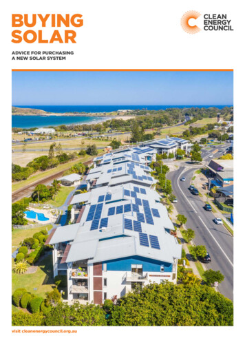
1IntroductionChapter 1 contains information about the features and functions of theSunPower Solar Inverter.About the SunPower Solar InverterThe SunPower Solar Inverter is designed to convert solar electric (photovoltaic orPV) power into utility-grade electricity that can be used by the home or sold to thelocal power company.Installing the inverter consists of mounting it to the wall and connecting the DCinput to a PV array and the AC output to the utility. See Figure 1-1 for a simplediagram of a typical installation.In order to operate, the inverter must have grid power available and connected. Itwill not provide backup power if the AC grid fails.Utility gridPhotovoltaic(PV) arrayUtility meterHarvestedsolar energySurplus powerrouted to utility gridPower routedto loadsMain utilityservice panelSunPower InverterFigure 1-1 Basic System Overview
IntroductionPV compatibilityThe inverter is designed to take advantage of solar modules configured as highvoltage PV string arrays—single crystalline, poly crystalline, or thin film—withan input voltage Maximum Power Point range (depending on inverter model) of195 to 550 Vdc, 240 to 550 Vdc, 240 to 480, or 200 to 400 Vdc. See “ElectricalSpecifications” on page A–2 for more information.Utility gridcompatibilityThe inverter can operate on either 240 V or 208 V nominal grid voltage. Theinverter senses the phase-to-phase voltage and automatically changes the powerlimit value for each grid voltage. The disconnect thresholds (see “AdjustableVoltage, Frequency and Reconnection Settings” on page A–10) remain the samebecause both nominal voltages have the same 120 Vac phase-to-neutralthresholds.Maximum PowerPoint Tracking(MPPT)The inverter uses a proprietary Maximum Power Point Tracking (MPPT)technology to harvest the maximum amount of energy from the solar array. MPPTlearns your array’s specific characteristics, maximizing its output at all times.High efficiencyThe high-frequency, solid-state design of the inverter is extremely efficient. SeeAppendix A, “Specifications” for the efficiency ratings of each model.ExpandableMultiple inverters may be networked together for increased net metering capacityor future system growth. The inverter has adjustable voltage and frequencydisconnect settings and can be aggregated above 30 kW on a single point-ofcommon-coupling (PCC). See “Adjustable Voltage, Frequency and ReconnectionSettings” on page A–10.Standard FeaturesThe inverter has the following standard features: 1–2Sealed inverter section protecting power electronic components;Liquid Crystal Display (LCD) providing easy-to-read system status and dailycumulative energy production information;Two LED indicator lights providing status and ground fault indication;Wiring/disconnect box providing protection for all AC and DC connectionsand eliminating exposed “live” wiring if the inverter is removed.The wiring/disconnect box has been designed to be physically mated to theelectronics section of the SunPower Inverter at the factory, but remains inplace as a non-serviceable item in the event that the inverter electronicssection is ever required to be removed. The inverter and wiring/disconnectbox together form an NEMA 3R enclosure to allow outdoor installation.975-0335-01-01
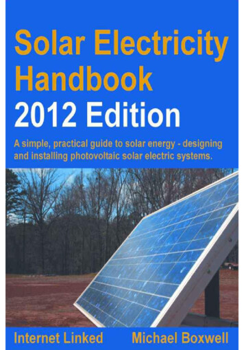
About the SunPower Solar InverterWARNING: Shock hazardThe 600 volt DC/AC disconnect in the wiring/disconnect box meets NEC Article 690. It isa non-serviceable component and shall remain in place. Separating the inverter andwiring/disconnect box, or removing the wiring/disconnect box cover can exposeenergized conductors. PV input circuits in the wiring box ahead of the switch remainenergized even when the switch is in the “off” position—hazardous voltage will still bepresent on the DC input (PV) terminals under the clear plastic insulation barrier inside thewiring/disconnect box.Front Panel FeaturesHeat SinkLCDLED IndicatorsWiring/Disconnect BoxDC/AC Disconnect SwitchMounting SlotsFigure 1-2 Front Panel FeaturesWiring/Disconnect BoxThe wiring/disconnect box is standard for all North American models of theinverter. The wiring/disconnect box provides a location for making AC, DC andground connections. It also contains the DC/AC (PV array/utility) disconnectswitch. When used with the inverter, the DC/AC disconnect switch is 600V ACand DC rated and is identified on the outside by an illustration showing the openand closed switch positions. The switch is lockable, and meets NEC Section 690requirements as a means of disconnect.975-0335-01-011–3
In jurisdictions where the local utility requires that the AC disconnect be capableof being locked in the open position by its service personnel, this disconnectswitch can also serve as a lockable isolating device.Important: In North America and other locations the wiring/disconnect box is anelectrical code requirement. Regulatory approval is based on the wiring/disconnect boxalways being attached to the inverter during operation. Any attempt to remove this boxwill invalidate the approvals and create an electrical hazard.
2InstallationChapter 2 provides information about installing the SunPower SolarInverter. It contains information on determining a suitable location forinstallation, PV array requirements, and procedures for mounting the unit.Installation OptionsThe inverter may be installed as a single inverter for a single PV array of one tothree PV strings. Only SPR-5000x models can accept three PV strings. Anexternal fuse box may be required when three PV strings are connected.The inverter can also be installed in a multiple inverter configuration. If multipleinverters are used, each inverter must be wired to an independent PV array.Communications between inverters can be enabled by installing network cablingto the inverter RJ-45 ports. See “Connecting Network Cable Between MultipleInverters” on page 3–15.Planning the InstallationEnsure that you have obtained all permits required by local authorities or utilitiesbefore beginning installation.Inverter LocationWARNING: Burn hazardDo not install in a location where people can accidentally come into contact with the frontof the inverter. High temperatures can be present on the face of the inverter, causing apotential burn hazard.In extreme conditions, the inverter chassis can reach temperatures over 70 C (158 F),which can cause skin burns if accidentally touched. Ensure that the inverter is locatedaway from normal traffic areas.
InstallationInverter failure due to improper installation will void the inverter warranty.Consider the following when determining where to install the inverter.Indoor/Outdoor Orientation Temperature The inverter must be mounted vertically on a wall or pole.Do not mount the inverter horizontally.If mounting the inverter indoors on a south-facing wall, ensure the wallis insulated to reduce the amount of heat absorbed by the inverter.Unless walls are properly insulated, avoid mounting the inverterindoors on any wall that is directly exposed to the sun.Ensure that the inverter is mounted in a location where the ambienttemperature range is -25 to 65 C (-13 to 149 F).Above 40 C (104 F), the inverter may derate power output.See“Output Power vs. Ambient Temperature” on page A–3 and“Environmental Specifications” on page A–4.At extreme cold temperatures, the front panel LCD may not functionnormally.GroundClearance Outdoors, the inverter requires at least 100 cm (39 inches) of clearancebetween the bottom of the unit and the ground.Distance To minimize resistance and resulting power loss, ensure that wirelengths between the PV array and the inverter and between the inverterand the main utility service panel are kept to a minimum.Maximum distances will depend on wire gauges used and PV arrayoutput voltages. Debris free2–2The inverter uses a Type 3R-rated enclosure (vertical mount only) thatcan be mounted indoors or outdoors. (Type 3R enclosures are intendedfor outdoor use primarily to provide a degree of protection againstfalling rain; and to be undamaged by the formation of ice on theenclosure.)While the 3R-rated enclosure protects the inverter from moisture,outdoor installations should be located away from lawn sprinklers andother sources of spray.A sun shade is recommended for outdoor installations. In bright sunconditions, when the inverter is at or near full output with an ambienttemperature above 40 C (104 F), shading the unit will help increaseinverter performance. A sun shade can also protect the inverter fromdust, debris, and birds. The sun shade should be made from an opaquematerial to provide shade for the heat sink. It should be large enoughand positioned so that it shades the heat sink when the inverter isoperating at full power—usually a four-hour time period centeredaround noon. Ensure that the shade is installed according to theminimum clearances specified on page 2–7. Excessive debris (such as dust, leaves, and cobwebs) can accumulateon the unit, interfering with wiring connections and ventilation. Do notinstall in a location where debris can accumulate (under a tree, forexample).975-0335-01-01
Planning the InstallationPV Array Voltage and MPPT RequirementsWARNING: Shock hazardWhenever a PV array is exposed to sunlight, a shock hazard exists at the output wires orexposed terminals. To reduce the risk of shock during installation, cover the array with anopaque (dark) material before making any connections, and always test for voltage beforetouching exposed wiring or devices.MPPT operationalwindowThe MPPT software maximizes the output energy of solar arrays as long as theoperating voltage is within the MPPT operational window. Ensure that the opencircuit voltage (Voc) of the PV array is within the MPPT operational window. See“Input voltage, Maximum Power Point Range” in Appendix A, “Specifications”for the MPPT operational window of each inverter model.Effects of array voltages outside of the MPPT operational window are shown inTable 2-1.Table 2-1 MPPT Operational WindowVoltageEffect of Array VoltageInverter ModeVoc Lower limit of MPPT rangeInverter not operating.Off-lineVMPP Lower limit of MPPT range(Voc Lower limit of MPPT range)On-line (low power)VMPP within MPPT rangeOperating voltage shifts to lower limit ofMPPT range; the array is not at itsmaximum power point.Maximum harvest of solar energy.VMPP between upper limit of MPPT rangeand absolute maximum VocDoes not allow maximum harvest of solarenergy.On-line (power derating)VMPP absolute maximum Voc(or Voc absolute maximum Voc)Inverter stops delivering power and shutsdown. Inverter may be damaged.Off-line (shutdown)VoltagerequirementsOn-line (MPPT window)The maximum power point voltage (VMPP) of a string connected to the invertershould preferably be above the lower limit of the MPPT range for that model. If itis below the lower limit of the MPPT range, the inverter continues to operate, butit regulates the PV voltage to the lower limit of the MPPT range. Because thearray is not operating at its maximum power point, this may result in lower thanexpected energy harvest. If Voc is below the lower limit of the MPPT range, theinverter remains off-line and does not deliver power.CAUTION: Equipment damageTo prevent damage to the inverter, the array voltage must never exceed 600 Voc (opencircuit voltage) under any condition.975-0335-01-012–3
InstallationThe short circuit current (Isc) rating of the array at any temperature must notexceed the Isc rating of the inverter. For maximum solar energy harvest, it isrecommended that the effective power output of the array be matched with theinput power capacity of the inverter.Guidelines for Matching PV Array Size to SunPower Solar Inverter Input 2–4Consider the expected Voc of the string under all possible conditions. Thepanel manufacturer provides a Voc rating per panel, but it is usually rated at25 C (77 F). Ensure that the Voc rating at the coldest ambient temperaturedoes not exceed 600 Vdc. Panel voltage increases in cold temperatures—thepanel manufacturer should be able to provide a coefficient of voltage increaseper degree.The NEC also has required temperature/voltage deratings that must be used;these can be found in Article 690 of the NEC. You need to determine thecoldest temperatures expected on the site, and size the array stringsaccordingly. To prevent inverter damage, the array’s maximum DC voltage inthe coldest expected temperature, with both manufacturer coefficient andNEC derating, must not exceed 600 Vdc.Panel voltage decreases in high temperatures. This will affect the panels’VMPP and Voc. Again, the manufacturer’s coefficient must be used with thehighest expected temperature to determine the minimum VMPP and Voc.975-0335-01-01
Mounting the InverterMounting the InverterDimensions and Knockout LocationsInverter dimensions and knockout locations are shown in Figure 2-1.Four 27 or 35 mm (1 or 1-3/8 inch) dual knockouts are provided on the back andbottom of the unit to accommodate wiring. -POS models have four 22 mm(7/8 inch) knockouts on the back of the wiring/disconnect box.Four 27 mm (1 inch) conduit holes on the sides of the wiring/disconnect box (twoon each side) are filled with plastic plugs (thread size Pg 21). These plugs can beremoved to insert conduit nipples as required for multiple inverter installations.Side conduit holes may be used to accommodate network communication cablesconnected between multiple inverters.1
DC power from the inverter before attempting any maintenance or cleaning or working on any circuits connected to the inverter. Turning off controls will not reduce this risk. Internal capacitors remain charged for 5 minutes after disconnecting all sources of power. 9. Normally grounded con