Transcription
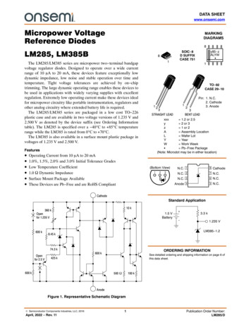
REF10041.2V and 2.5V MicropowerVOLTAGE REFERENCEFEATURESDESCRIPTION INITIAL ACCURACY:REF1004-1.2 4mVREF1004-2.5 20mV MINIMUM OPERATING CURRENT:REF1004-1.2 10µAREF1004-2.5 20µA EXCELLENT LONG TERMTEMPERATURE STABILITY VERY LOW DYNAMIC IMPEDANCE OPERATES UP TO 20mA PACKAGE: 8-Lead SOICThe REF1004-1.2 and REF1004-2.5 are two terminalbandgap reference diodes designed for high accuracywith outstanding temperature characteristics at lowoperating currents. Prior to the introduction of theREF1004 Micropower Voltage References, accuracyand stability specifications could only be attained byexpensive screening of standard devices. The REF1004is a cost effective solution when reference voltageaccuracy, low power, and long term temperature stability are required.REF1004 is a drop-in replacement for the LT1004 aswell as an upgraded replacement of the LM185/385series references. The REF1004C is characterized foroperation from 0 C to 70 C and the REF1004I ischaracterized for operation from –40 C to 85 C.The REF1004 is offered in an 8-lead Plastic SOICpackage and shipped in anti-static rails or tape andreel.APPLICATIONS BATTERY POWERED TEST EQUIPMENT PORTABLE MEDICAL INSTRUMENTATION PORTABLE COMMUNICATIONS DEVICES A/D AND D/A CONVERTERS NOTEBOOK AND PALMTOP COMPUTERSTypical Operating CircuitNC18CathodeNC27NCNC36CathodeAnode45NC(Top View)International Airport Industrial Park Mailing Address: PO Box 11400Tel: (520) 746-1111 Twx: 910-952-1111 Cable: BBRCORP SBVS0021992 Burr-Brown Corporation Tucson, AZ 85734 Street Address: 6730 S. Tucson Blvd. Tucson, AZ 85706Telex: 066-6491 FAX: (520) 889-1510 Immediate Product Info: (800) 548-6132PDS-1172Printed in U.S.A. October, 1993
SPECIFICATIONSELECTRICALTA 25 C unless otherwise noted.REF1004-1.2PARAMETERREFERENCE VOLTAGEREF1004C(1)REF1004I(2)AVERAGE TEMPERATURECOEFFICIENTMINTYPMAXMINTYPMAXUNITSIR N IR 20mA20MINIMUM OPERATIONCURRENT(3)8IMIN IR 1mAREVERSE BREAKDOWNVOLTAGE CHANGE WITHCURRENTIR 100µAWIDE BAND NOISE (RMS)10Hz IR 10kHzIR 100µALONG TERM STABILITYTA 25 C 0.1 CIR 100µA2010ppm/ C1211.5(3)1020(3)1mA IR 20mAREVERSE : (1) This specification applies over the full operating temperature range of 0 C TA 70 C. (2) This specification applies over the full operatingtemperature range of 40 C TA 85 C. (3) Denotes the specifications which apply over the full operating temperature range.ORDERING .2REF1004I-2.5TAVZ0 C to 70 C0 C to 70 C–40 C to 85 C–40 C to 85 ICSOICSOICSOICNOTE: Available in Tape and Reel, Add –TR to Model Number.ORDERING INFORMATIONABSOLUTE MAXIMUM RATINGSReverse Breakdown Current . 30mAForward Current . 10mAOperating Temperature RangeREF1004C . 0 C to 70 CREF1004I . –40 C to 85 CStorage TemperatureREF1004C . –65 C to 150 CREF1004I . –65 C to 150 CLead Temperature (soldering, 10s) . 300 -2.5PART MARKINGBBREF0412BBREF0425BBREF0412BBREF0425PACKAGE OICSOICPACKAGE DRAWINGNUMBER(1)182182182182NOTE: (1) For detailed drawing and dimension table, please see end of datasheet, or Appendix D of Burr-Brown IC Data Book.The information provided herein is believed to be reliable; however, BURR-BROWN assumes no responsibility for inaccuracies or omissions. BURR-BROWN assumesno responsibility for the use of this information, and all use of such information shall be entirely at the user’s own risk. Prices and specifications are subject to changewithout notice. No patent rights or licenses to any of the circuits described herein are implied or granted to any third party. BURR-BROWN does not authorize or warrantany BURR-BROWN product for use in life support devices and/or systems. REF10042
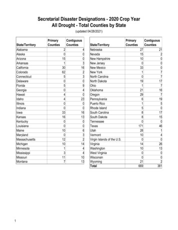
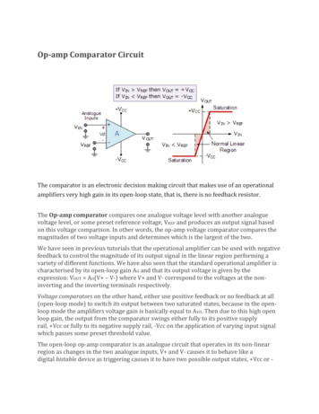
TYPICAL PERFORMANCE CURVES 1.2VTA 25 C unless otherwise noted.REVERSE CHARACTERISTICSFORWARD CHARACTERISTICS1001.2TA 25 CForward Voltage (V)Reverse Current (µA)–40 C TA 85 PERATURE DRIFT10100REVERSE VOLTAGE CHANGE1.24516Output Voltage Change (mV)Reverse Voltage (V)1Forward Current (mA)Reverse Voltage (V)1.2401.2351.230–40 C TA 85 C128401.225–55–35–155254565Temperature ( C)85105–40.01125100REVERSE DYNAMIC IMPEDANCEREVERSE DYNAMIC IMPEDANCE10kf 25Hz–40 C to 85 CDynamic Impedance (Ω)Reverse Impedance (Ω)101Reverse Current (mA)1001010.10.010.1TA 25 CIREF 100µA1k1001010.10.111010100Reverse Current (mA)1001k10k100k1MFrequency (Hz) 3REF1004
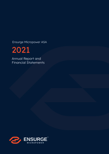
TYPICAL PERFORMANCE CURVES 1.2V(CONT)TA 25 C unless otherwise noted.FILTERED OUTPUT NOISENOISE VOLTAGE7007060500Integrated Noise (µV)IREF 100µATA 25 C400300200100IREF NSE 00300Time (µSec) REF100410kCutoff Frequency (Hz)Frequency (Hz)Voltage (V)Noise (nV/ Hz)6004400500600100k
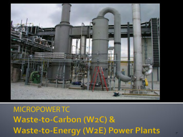
TYPICAL PERFORMANCE CURVES 2.5VTA 25 C unless otherwise noted.REVERSE VOLTAGE CHANGEREVERSE CHARACTERISTICS6100Output Voltage Change (mV)Reverse Current (µA)–40 C TA 85 C1015–40 C TA 85 0Reverse Current (mA)Reverse Voltage (V)TEMPERATURE DRIFTFORWARD CHARACTERISTICS1.22.520TA 25 C2.515Reference Voltage (V)Forward Voltage 4800.00.012.4750.1110–55100–35–15Forward Current (mA)REVERSE DYNAMIC IMPEDANCE8510512510kDynamic Impedance (Ω)f 25Hz–40 C to 85 CReverse Impedance (Ω)254565Temperature ( C)REVERSE DYNAMIC IMPEDANCE10001001010.10.015TA 25 CIREF y (Hz)Reverse Current (mA) 5REF1004
TYPICAL PERFORMANCE CURVES 2.5V(CONT)TA 25 C unless otherwise noted.NOISE VOLTAGEFILTERED OUTPUT NOISE14001201200100Integrated Noise SPONSE 100200300Time (µSec) REF100410kCutoff Frequency (Hz)Frequency (Hz)Voltage (V)Noise (nV/ Hz)IREF 100µA1000IREF 100µA100µA6400500600100k
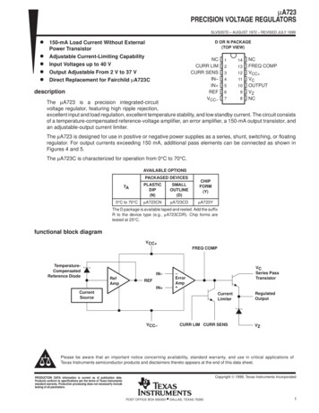
1.5V (see Note)VI 5V3kΩ100µA1.235V22ΩOutput REF1004-1.2REF1004-1.25µFNOTE: Output regulatesto 1.285V for IO 0.FIGURE 1. Low-Noise Reference.FIGURE 3. 1.2V Reference from 1.5V 004-2.5FIGURE2. Micropower Reference from 9V Battery.FIGURE 4. 2.5V Reference.Battery OutputR1(1)1%12V1MΩTLC271LO Battery Low133kΩ1%REF1004-1.2NOTE: (1) R1 sets trip point, 60.4kΩ per cell for 1.8V per cell.FIGURE 5. Lead-Acid Low-Battery-Voltage Detector. 7REF1004
PACKAGE OPTION ADDENDUMwww.ti.com13-Aug-2021PACKAGING INFORMATIONOrderable DeviceStatus(1)Package Type Package Pins PackageDrawingQtyEco Plan(2)Lead finish/Ball materialMSL Peak TempOp Temp ( C)Device Marking(3)(4/5)(6)REF1004C-1.2ACTIVESOICD875RoHS & GreenNIPDAULevel-3-260C-168 HR0 to 70REF0412REF1004C-1.2/2K5ACTIVESOICD82500RoHS & GreenNIPDAULevel-3-260C-168 HR0 to 70REF0412REF1004C-2.5ACTIVESOICD875RoHS & GreenNIPDAULevel-3-260C-168 HR0 to 70REF0425REF1004C-2.5/2K5ACTIVESOICD82500RoHS & GreenNIPDAULevel-3-260C-168 HR0 to 70REF0425REF1004I-1.2ACTIVESOICD875RoHS & GreenNIPDAULevel-3-260C-168 HR-40 to 85REF0412REF1004I-1.2/2K5ACTIVESOICD82500RoHS & GreenNIPDAULevel-3-260C-168 HR-40 to 85REF0412REF1004I-1.2E4ACTIVESOICD875RoHS & GreenNIPDAULevel-3-260C-168 HR-40 to 85REF0412REF1004I-2.5ACTIVESOICD875RoHS & GreenNIPDAULevel-3-260C-168 HR-40 to 85REF0425REF1004I-2.5/2K5ACTIVESOICD82500RoHS & GreenNIPDAULevel-3-260C-168 HR-40 to 85REF0425(1)The marketing status values are defined as follows:ACTIVE: Product device recommended for new designs.LIFEBUY: TI has announced that the device will be discontinued, and a lifetime-buy period is in effect.NRND: Not recommended for new designs. Device is in production to support existing customers, but TI does not recommend using this part in a new design.PREVIEW: Device has been announced but is not in production. Samples may or may not be available.OBSOLETE: TI has discontinued the production of the device.(2)RoHS: TI defines "RoHS" to mean semiconductor products that are compliant with the current EU RoHS requirements for all 10 RoHS substances, including the requirement that RoHS substancedo not exceed 0.1% by weight in homogeneous materials. Where designed to be soldered at high temperatures, "RoHS" products are suitable for use in specified lead-free processes. TI mayreference these types of products as "Pb-Free".RoHS Exempt: TI defines "RoHS Exempt" to mean products that contain lead but are compliant with EU RoHS pursuant to a specific EU RoHS exemption.Green: TI defines "Green" to mean the content of Chlorine (Cl) and Bromine (Br) based flame retardants meet JS709B low halogen requirements of 1000ppm threshold. Antimony trioxide basedflame retardants must also meet the 1000ppm threshold requirement.(3)MSL, Peak Temp. - The Moisture Sensitivity Level rating according to the JEDEC industry standard classifications, and peak solder temperature.Addendum-Page 1Samples
PACKAGE OPTION ADDENDUMwww.ti.com(4)13-Aug-2021There may be additional marking, which relates to the logo, the lot trace code information, or the environmental category on the device.(5)Multiple Device Markings will be inside parentheses. Only one Device Marking contained in parentheses and separated by a " " will appear on a device. If a line is indented then it is a continuationof the previous line and the two combined represent the entire Device Marking for that device.(6)Lead finish/Ball material - Orderable Devices may have multiple material finish options. Finish options are separated by a vertical ruled line. Lead finish/Ball material values may wrap to twolines if the finish value exceeds the maximum column width.Important Information and Disclaimer:The information provided on this page represents TI's knowledge and belief as of the date that it is provided. TI bases its knowledge and belief on informationprovided by third parties, and makes no representation or warranty as to the accuracy of such information. Efforts are u
REF1004 Micropower Voltage References, accuracy and stability specifications could only be attained by expensive screening of standard devices. The REF1004 is a cost effective solution when reference voltage accuracy, low power, and long term temperature sta-bility are required. REF1004 is a drop-in replacement for the LT1004 as