Transcription
SINAMICS G: Axispositioning with theSINA POS blockSINAMICS G120 / SIMATIC en/view/109736845SiemensIndustryOnlineSupport
Warranty and liabilityWarranty and liability Siemens AG 2017 All rights reservedNoteThe Application Examples are not binding and do not claim to be completeregarding the circuits shown, equipping and any eventuality. The ApplicationExamples do not represent customer-specific solutions. They are only intendedto provide support for typical applications. You are responsible for ensuring thatthe described products are used correctly. These Application Examples do notrelieve you of the responsibility to use safe practices in application, installation,operation and maintenance. When using these Application Examples, yourecognize that we cannot be made liable for any damage/claims beyond theliability clause described. We reserve the right to make changes to theseApplication Examples at any time without prior notice.If there are any deviations between the recommendations provided in theseApplication Examples and other Siemens publications – e.g. Catalogs – thecontents of the other documents have priority.We do not accept any liability for the information contained in this document.Any claims against us – based on whatever legal reason – resulting from the use ofthe examples, information, programs, engineering and performance data etc.,described in this Application Example shall be excluded. Such an exclusion shallnot apply in the case of mandatory liability, e.g. under the German Product LiabilityAct (“Produkthaftungsgesetz”), in case of intent, gross negligence, or injury of life,body or health, guarantee for the quality of a product, fraudulent concealment of adeficiency or breach of a condition which goes to the root of the contract(“wesentliche Vertragspflichten”). The damages for a breach of a substantialcontractual obligation are, however, limited to the foreseeable damage, typical forthe type of contract, except in the event of intent or gross negligence or injury tolife, body or health. The above provisions do not imply a change of the burden ofproof to your detriment.Any form of duplication or distribution of these Application Examples or excerptshereof is prohibited without the expressed consent of the Siemens AG.SecurityinformationSiemens provides products and solutions with industrial security functions thatsupport the secure operation of plants, systems, machines and networks.In order to protect plants, systems, machines and networks against cyberthreats, it is necessary to implement – and continuously maintain – a holistic,state-of-the-art industrial security concept. Siemens’ products and solutions onlyform one element of such a concept.Customer is responsible to prevent unauthorized access to its plants, systems,machines and networks. Systems, machines and components should only beconnected to the enterprise network or the internet if and to the extent necessaryand with appropriate security measures (e.g. use of firewalls and networksegmentation) in place.Additionally, Siemens’ guidance on appropriate security measures should betaken into account. For more information about industrial security, please mens’ products and solutions undergo continuous development to make themmore secure. Siemens strongly recommends to apply product updates as soonas available and to always use the latest product versions. Use of productversions that are no longer supported, and failure to apply latest updates mayincrease customer’s exposure to cyber threats.To stay informed about product updates, subscribe to the Siemens IndustrialSecurity RSS Feed under ing with SINA POSEntry ID: 109736845, V1.0,06/20172
Table of contentsTable of contentsWarranty and liability . 21Introduction . 41.11.22Engineering . 52.12.22.33 Siemens AG 2017 All rights reservedInstalling the hardware . 25IP addresses and device names . 26Download the project to the components . 26Operating the Application Example . 296.16.1.16.1.26.1.36.1.46.1.56.27Creating the project configuration . 15Commissioning the SINAMICS drive . 18Basic positioner . 22Configuring the S7 program . 23Installation and Commissioning . 255.15.25.36Data exchange to the SINAMICS drive . 8SINA POS function block . 9Safe Torque Off (STO) . 13STO via digital inputs . 13STO as per SIL 3 with power module PM240-2 . 14Configuration and Settings. 154.14.24.34.45Overview. 5Description of the core functionality . 6Hardware and software components . 6Function Principle of the Application Example . 83.13.23.33.3.13.3.24Overview. 4Requirements of the application example . 4Operation via HMI . 29Start screen . 30Operating the “SINA POS” block . 31System functions . 33Support information . 33Display of faults . 34Operation via the watch table . 35Appendix . 367.17.27.3Positioning with SINA POSEntry ID: 109736845, V1.0,Service and Support . 36Links and Literature . 37Change documentation . 3706/20173
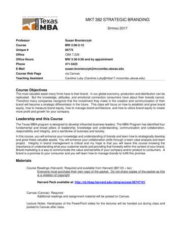
1 Introduction1Introduction1.1OverviewThe SIMATIC S7-1200 can be operated as a PROFINET controller. For this, thePROFINET-capable SINAMICS G120 drive can be used as PROFINET device andbe controlled by SIMATIC S7-1200.This application example specifies a setpoint position for a SINAMICS G120 drive.The drive will then move to the setpoint position using the basic positioner (EPos)function.Overview of the application exampleThe following figure provides an overview of the application example.Figure 1-1: OverviewSINAMICS G120 Siemens AG 2017 All rights reservedSIMATIC S7-1200SIMATIC HMIPROFINET IE1.2Requirements of the application exampleTable 1-1: Requirements of the application exampleRequirementAccess to process dataExplanationThe control word switches the SINAMICS G120 drive on or offand specifies the setpoint speed value.Pending faults at the drive are displayed and acknowledged.PositioningThe drive is positioned with the basic positioning function.Monitoring thecommunicationThe communication connection between the controller and thedrive are monitored for interruptions.Safety function of theSINAMICS G120The SINAMICS G120 drive will have the option of performinga fail-safe shutdown (STO).Positioning with SINA POSEntry ID: 109736845, V1.0,06/20174
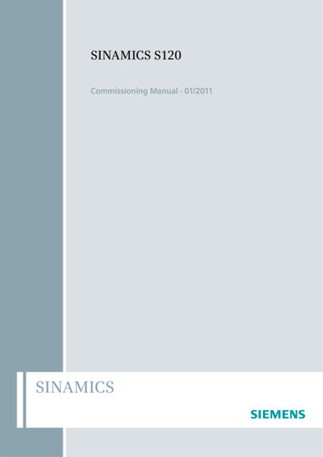
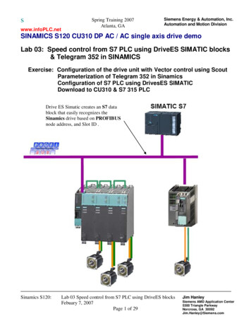
2 Engineering2EngineeringThis application example shows the PROFINET connection of a SINAMICS G120to a SIMATIC S7-1215C with SINAMICS Startdrive. The "SINA POS" block is usedfor controlling and positioning the drive.2.1OverviewSchematic layoutThe figure below shows a schematic overview of the most important components ofthe solution:Figure 2-1: Interconnection of the componentsSINAMICS G120CU250S-2 PN Siemens AG 2017 All rights reservedSIMATIC S7-1215CSIMATIC HMI KTP700PROFINET IEPG/PCMotor with encoderAdvantagesThe use of the standard block “SINA POS” offers a quick and simple option tocontrol and position the SINAMICS drive.Topics not covered by this applicationThis application example does not contain a description of: Structure and principle of operation of the “SINA POS” block Configuration of the safety functions in the SINAMICS G120 driveAssumed knowledgeBasic knowledge of the TIA Portal and Startdrive is assumed.Positioning with SINA POSEntry ID: 109736845, V1.0,06/20175
2 Engineering2.2Description of the core functionalityConfiguring the communicationBoth the SIMATIC controller and the SINAMICS converter are configured andprogrammed in the TIA Portal. To do this, the following data are automaticallygenerated in the hardware configuration: IP addresses PROFINET device names I/O address ranges for the data to be exchanged between the SIMATICcontroller and the SINAMICS drive.However, they can be modified at any time. Which process data are exchangedbetween SIMATIC controller and SINAMICS drive is specified by the frame type (inthe example: standard telegram 111). The telegram type is also configured in thehardware configuration.Data exchange Siemens AG 2017 All rights reservedData exchange between SINAMICS G120 and SIMATIC S7-1200 is done with the“SINA POS” block in the process data range. Process data is transferred cyclically,which means in each bus cycle.PositioningThe axis of the SINAMICS drive is positioned using only the "SINA POS" standardblock. This standard block uses the basic positioning function (EPos) configured inthe drive.2.3Hardware and software componentsThe application was created with the following components:Hardware componentsTable 2-1: Hardware componentsComponentQty.Article numberNoteSIMATIC CPU 1215CDC/DC/DC(FW 4.2.1)16ES7215-1AG40-0XB0Alternatively, you can also usea different CPU.SINAMICS CU250S-2PN Vector (FW 4.7.6)16SL3246-0BA22-1FA0-SINAMICS PM240-2IP2016SL3210-1PB13-0ULx-Asynchronous motor11LA7060-4AB10-ZHTL speed encoder11XP8001-1SIMATIC PanelKTP700 Basic PN16AV2123-2GB03-0AX0PROFINET linesPROFINET connectorPositioning with SINA POSEntry ID: 109736845, V1.0,06/20176Alternatively, you can use adifferent asynchronous motor.The panel is optional.6XV1840-2AH10-6GK1901-1BB10-2AA0-6
2 EngineeringSoftware componentsTable 2-2: Software componentsComponentQty.Article numberNoteSTEP 7Professional V1416ES7822-1.04-.-WinCC AdvancedV1416AV210.- .4-0-SINAMICS StartdriveV1416SL3072-4EA02-0XG0-License for the Basicpositioner16SL3054-4AG00-2AA0Z E01with memory cardExample files and projectsThe following list contains all files and projects that are used in this applicationexample.Table 2-3: Example files and projects Siemens AG 2017 All rights reservedComponent109736845 G120 CU250S2PN at S7 1200SINA POS v10.zip109736845 G120 CU250S2PN at S7 1200SINA POS DOCU v10.pdfPositioning with SINA POSEntry ID: 109736845, V1.0,06/2017NoteThis zip file contains theSTEP 7 V14 project.This document.7
3 Function Principle of the Application ExampleFunction Principle of the ApplicationExample3Program overviewFigure 3-1: Program overviewMain [OB1]SINA POS[FB 284]InstSinaPos[DB 284]DPWR DAT Siemens AG 2017 All rights reservedDPRD DATUser program3.1InstructionsData blocksData exchange to the SINAMICS driveCommands DPWR DAT and DPRD DATThe “SINA POS” block establishes the cyclic communication to a drive. To do this,the block accesses the following command: DPWR DAT (writing consistent data of a DP standard slave) DPRD DAT (reading consistent data of a DP standard slave)These instructions ensure that the consistency is maintained across the entireprocess data, i.e. all elements of the process data of a device are from the samebus cycle or are transferred within a bus cycle.NoteFor more information on the commands DPWR DAT and DPRD DAT refer tothe Online Help of the TIA Portal.Control words and status word via standard telegramThe “SINA POS” function block is used to cyclically control a SINAMICS G120drive with the standard telegram 111 (positioning drive with extended functions).Positioning with SINA POSEntry ID: 109736845, V1.0,06/20178
3 Function Principle of the Application ExampleTable 3-1: Transmission telegram to the driveAddressNameContentPZD 1STW1Control word 1PZD 2POS STW1Control word 1 for the basic positionerPZD 3POS STW2Control word 2 for the basic positionerPZD 4STW2Control word 2PZD 5OVERRIDESetpoint speed valuePZD 6MDI TARPOSPosition setpoint value with direct setpointspecification (MDI)MDI VELOCITYMDI velocityPZD 10MDI ACCMDI accelerationPZD 11MDI DECMDI delayPZD 7PZD 8PZD 9PZD 12-not assignedTable 3-2: Receive telegram from the drive Siemens AG 2017 All rights reservedAddressNameContentPZD 1ZSW1Status word 1PZD 2POS ZSW1Status word 1 for the basic positionerPZD 3POS ZSW2Status word 2 for the basic positionerPZD 4ZSW2Status word 2PZD 5MELDWStatus word for messagesPZD 6XIST AActual position valueNIST BActual speed valuePZD 10WARN CODENumber of the currently active warningPZD 11FAULT CODENumber of the currently active faultPZD 7PZD 8PZD 9PZD 123.2-not assignedSINA POS function blockThe “SINA POS” block and its documentation is contained in the .siemens.com/cs/ww/en/view/109475044Block callThe “SINA POS” block can be called in the following organization blocks (OBs): Cyclic task: OB1 Interrupt OB: for example OB32Positioning with SINA POSEntry ID: 109736845, V1.0,06/20179
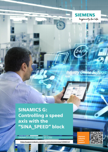
3 Function Principle of the Application ExampleFigure 3-2: Call of SINA POSSINA diateStopBOOL Siemens AG 2017 All rights atusWORDINTOverDecDiagIDWORDDWORDConfigEPosHW IOHWIDSTWHW IOHWIDZSWBOOLBlock parametersThe following table lists the input and output parameter of the “SINA POS” block.Table 3-3: "SINA POS" input parametersNameTypeStart valueFunctionModePosINT0Operating mode:1: Positioning, relative2: Positioning, absolute3: Positioning as setup4: Homing – reference point approach5: Homing – reference point definition6: Traversing block7: Jog mode8: Jog mode, incrementalEnableAxisBOOLFALSEStart/stop the driveCancelTraversingBOOLTRUEFALSE: discard active positioning jobTRUE: do not discardIntermediateStopBOOLTRUEFALSE: active move command isinterruptedTRUE: no intermediate stopPositiveBOOLFALSEpositive directionPositioning with SINA POSEntry ID: 109736845, V1.0,06/201710
3 Function Principle of the Application Example Siemens AG 2017 All rights reservedNameTypeStart valueFunctionNegativeBOOLFALSEnegative directionJog1BOOLFALSEJog mode, signal source 1Jog2BOOLFALSEJog mode, signal source 2FlyRefBOOLFALSEFALSE: disable Homing on the flyTRUE: enable Homing on the flyAckErrorBOOLFALSEAcknowledgment of errorsExecuteModeBOOLFALSEEnable positioning job or setpoint transferPositionDINT0Position setpoint value in Length Unit(see Section Path unit LU)VelocityDINT0Speed setpoint value in Length Unit/min(see Section Path unit LU)OverVINT100Velocity override 0 – 199%OverAccINT100Acceleration override 0 – 100%OverDecINT100Deceleration override 0 – 100%ConfigEPosDWORD16#00000003The following bits of the control word ofthe drive are pre-assigned:Bit 1: OFF2Bit 2: OFF3HWIDSTWHW IO0Hardware ID setpoint value (see SectionTelegram slot)HWIDZSWHW IO0Hardware ID actual value (see sectionTelegram slot)Table 3-4: "SINA POS" output parametersNameTypeStart valueFunctionErrorBOOLFALSEGeneral faultStatusWORD0Display of status values:16#7002: no fault16#8401: Fault in the drive16#8402: On-inhibit16#8403: Homing on the fly could not beinitiated16#8600: DPRD DAT error16#8601: DPWR DAT error16#8202: incorrect mode selected16#8203: incorrect setpoint valuesconfigured16#8204: incorrect traversing blocknumber selectedDiagIDWORD0Extended communication faultAxisEnabledBOOLFALSEDrive readyAxisErrorBOOLFALSEDrive fault activeAxisWarnBOOLFALSEDrive warning activeAxisPosOkBOOLFALSEAxis has reached target positionAxisRefBOOLFALSERefernce point setActVelocityDINT0actual velocity in Length Unit/minActPositionDINT0actual position in Length UnitActModeINT0currently active modePositioning with SINA POSEntry ID: 109736845, V1.0,06/201711
3 Function Principle of the Application ExampleNameTypeStart valueFunctionLockoutBOOLFALSEOn-inhibit of the drive is activeEPosZSW1WORD0Status of the EPos ZSW1EPosZSW2WORD0Status of the EPos ZSW2ActWarnWORD0current warning numberActFaultWORD0current fault numberPath unit LU (Length Unit)The "SINA POS" block works with the neutral path unit LU (Length Unit). The pathunit LU can be a distance (e.g. 1LU 1mm) or an axis angle (e.g. 1LU 1milligrad). This is defined in when configuring the drive.Telegram slotThe block inputs HWIDSTW and HWIDZSW must reference to the hardware ID ofthe standard telegram. Siemens AG 2017 All rights reservedFigure 3-3: Entering the telegram slotWhen using a PROFINET connection between the SIMATIC controller and theSINAMICS G120 drive, the same hardware ID must be configured for block inputsHWIDSTW and HWIDZSW.NoteFor more information on the “SINA POS” block and its function refer to theOnline Help of the TIA Portal or to the “DriveLib” /cs/ww/en/view/109475044Positioning with SINA POSEntry ID: 109736845, V1.0,06/201712
3 Function Principle of the Application ExampleInstance data blockThe “SINA POS” block interface is restricted to few inputs and outputs. All signalsof standard telegram 111 are available via the instance data block at all times.The instance data block “SINA POS DB” contains the following information: Function block inputs (1) Function block outputs (2) An area with static tags (3) The standard telegram 111 structure in the statistical tag range (4)Figure 3-4: Structure of the instance data block1 Siemens AG 2017 All rights reserved2343.3Safe Torque Off (STO)3.3.1STO via digital inputsThe converter with the “Safe Torque Off” (STO) function active prevents theunwanted startup of machine components. This safety function can be configuredwith specific digital inputs for a SINAMICS G120 drive with a control unit with safetyfunction. To do this, the safety functions must be enabled in the control unit.NoteA detailed description of the configuration of the safety function STO using digitalinputs can be found in the application example “SINAMICS G: Speed Control ofa G110M / G120 (Startdrive) with S7-1500 (TO) via PROFINET or PROFIBUSwith Safety Integrated (via Terminal) and en/view/78788716If the drive is run with EPOS and the STO function is active, the drive can show thealarm message F07490 (EPOS: Enable signal withdrawn while traversing).Positioning with SINA POSEntry ID: 109736845, V1.0,06/201713
3 Function Principle of the Application Example3.3.2STO as per SIL 3 with power module PM240-2The PM240-2 power modules in sizes FSD, FSE and FSF can be used to realizethe “Safe Torque Off” (STO) according to PLe as per EN 13849-1 and according toSIL 3 as per IEC61508. Two terminal blocks (STO A and STO B) and two Dipswitches are available on the front side of the power module.NoteMore information on how to use the STO safety function as per SIL 3 with thePM240-2 power module can be found in the “SINAMICS G120 power modulePM240-2” manual. Siemens AG 2017 All rights /en/view/109482011Positioning with SINA POSEntry ID: 109736845, V1.0,06/201714
4 Configuration and Settings4Configuration and SettingsThe step tables below describe how to configure the S7-1200 and theSINAMICS G120 drive. The configuration of the operator panel is not described inthis chapter.A requirement is that the software listed in Table 2-2 is installed on your PC/PG.4.1Creating the project configurationTable 4-1: Creating the project configuration Siemens AG 2017 All rights reservedNo.Action1.Open TIA Portal and create a newproject.2.Double-click on “Add new device“.3.Add your desired controller:1. Select “Controller”.2. Select the desired CPU.3. Then click on “OK”.Positioning with SINA POSEntry ID: 109736845, V1.0,06/2017Remark15
4 Configuration and SettingsNo.4.ActionOpen the device configuration of theCPU and configure the PROFINETinterface:1. Open the “Properties” of theCPU.2. Select “Ethernet addresses”.3. Add a new subnet.4. Enter the desired IP address andsubnet mask.5. You can also specify thePROFINET device name in thismask.Remark345Configuring the SINAMICS drive Siemens AG 2017 All rights reservedTable 4-2: Adding the driveNo.Action1.Select the desired SINAMICS drive:1. In the “devices and networks”editor, go to the “Network view”.2. Now drag the desiredPROFINET-capable SINAMICSdrive into the graphic area.2.Connect the Ethernet connections ofthe SIMATIC controller and theSINAMICS drive with each other.3.Assign a power module to the driveadded in the network view. (This stepis not necessary when using aG120C drive):1. Open the “Device view”.2. Select a power module from thehardware catalog and add it tothe drive.Positioning with SINA POSEntry ID: 109736845, V1.0,06/2017Remark16
4 Configuration and Settings Siemens AG 2017 All rights reservedNo.Action4.Configure the PROFINET interface ofthe drive:1. Open the “Properties” of thedrive.2. You can set the IP address andthe device name in the“PROFINET interface” settings.5.For data exchange between CPU anddrive, leave the setting at standardtelegram 1 unchanged. The standardtelegram 111 required for the"SINA POS" block can only beconfigured after the basic positionerhas been activated.RemarkAdding the HMI (optional)Table 4-3: Adding the HMINo.Action1.Add the HMI in the “Network view”.2.Configure an HMI connectionbetween CPU and HMI.3.Then, check the PROFINETaddresses set.Positioning with SINA POSEntry ID: 109736845, V1.0,06/2017Remark17
4 Configuration and Settings4.2Commissioning the SINAMICS driveAfter generating the project configuration, you have to commission the SINAMICSG120 drive. When doing so, the commissioning wizard in Startdrive is followed.NoteInformation on the configuration and commissioning of drives can be found in theTIA Portal online help.Table 4-4: Commissioning the drive Siemens AG 2017 All rights reservedNo.Action1.The drive must be assigned thedevice name to be able to establishan online connection to the drive. Todo this, select the interface used inthe “Online access” folder. Once theavailable participants have beenupdated (Update accessibledevices), the devices connected toPROFINET are displayed. Fordrives, there is the option to assignIP address and device name in the“Online & diagnostics” menu subitem.2.You can assign IP address anddevice name in the “Online &diagnostics” menu sub-item.1. Enter the IP address or thedevice name in the respectivefield.2. Then, assign the drive theaddress or device name.Remark123.When the assigned data (IPaddress and device name) isidentical with the configuration ofthe drive (chapter 4.1), Startdrivecan be used to establish an onlineconnection to the drive. To do so,select the drive in the project treeand click “Go online” in the toolbar.Positioning with SINA POSEntry ID: 109736845, V1.0,06/201718
4 Configuration and Settings Siemens AG 2017 All rights reservedNo.Action4.The Commissioning Wizard can befound in the drive folder under“Commissioning”.5.Follow the Commissioning Wizard inthe "Expert" application class. Fortips, please refer to the TIA Portalonline help.Activate the Basic positioner andselect "Speed control (withencoder)" as control mode.6.Configure standard telegram 111 tocontrol the communication.Positioning with SINA POSEntry ID: 109736845, V1.0,06/2017Remark19
4 Configuration and SettingsNo.ActionEnter the motor data of the motoryou are using.8.The ramp-up and ramp-down timesstated under "Important parameters"have no relevance for the basicpositioner.9.Enter the data of the encoder youare using.If the used encoder is not includedin the list, switch to "Enter encoderdata" in the encoder configuration.Now you can enter encoder data. Siemens AG 2017 All rights reserved7.RemarkPositioning with SINA POSEntry ID: 109736845, V1.0,06/201720
4 Configuration and SettingsNo.ActionUse the "Mechanical system"configuration display to enter the"LU per load revolution". Thissetting is used as the calculationbasis for defining velocity andposition values.11.As a last step of the commissioningwizard, you have to save the drivesettings. To do so, check the “RAMdata to EEPROM” checkbox andfinish the wizard.12.Then disconnect the onlineconnection to the drive and load theconfiguration stored in the drive intothe offline project.13.Save the TIA Portal project. Siemens AG 2017 All rights reserved10.RemarkPositioning with SINA POSEntry ID: 109736845, V1.0,06/2017-21
4 Configuration and Settings4.3Basic positionerThe Basic positioner (EPos) moves an axis to a target position on a positioncontrolled basis.NoteA description of the basic positioner can be found in the Function Manual"SINAMICS G120, Basic Positioner (EPos) for CU250-2 Control en/view/109483005The basic positioner contains the following operating modes:Table 4-5: EPos operating modes Siemens AG 2017 All rights reservedOperating modeMeaningEnter setpoint value directly(MDI)The external control specifies the position setpoint for theaxis.Selecting traversing blocksThe converter has position setpoints stored in differenttraversing blocks. The external control selects atraversing block.ReferencingA homing run creates a reference for positionmeasurement in the converter to the machine.Jog mode (JOG)This function is used to move the axis in increments(during setup).When the drive is configured, some settings of the basic positioner can be made inthe functional view of the drive parameters.Figure 4-1: EPos Setting optionsNoteUseful support on the setting options of the basic positioner under Startdrive canbe found in the TIA Portal online help.Positioning with SINA POSEntry ID: 109736845, V1.0,06/201722
4 Configuration and Settings4.4Configuring the S7 programThe following step table shows how to configure a S7 program with the“SINA POS” function block.Table 4-6: Configuring the S7 program Siemens AG 2017 All rights reservedNo.Action1.Select the S7-1200 in the projecttree.2.Open the libraries and select the“SINA POS” block from theDriveLib library matching theSIMATIC controller used.3.Then add the block the “Programblocks” folder in the controller.Positioning with SINA POSEntry ID: 109736845, V1.0,06/2017Remark23
4 Configuration and Settings Siemens AG 2017 All rights reservedNo.Action4.Call the “SINA POS” block in theMain OB (OB1). Assign the functionblock an instance data block. Thenumber of the instance data blockcan be selected by the user.5.Connect the inputs and outputs ofthe "SINA POS" function block asdescribed in chapter 3.2.6.It is recommended to copy theinputs and outputs of the block"SINA POS" into a control panel.(see Figure 6-11)7.Save the project and load theprogram into the controller.Positioning with SINA POSEntry ID: 109736845, V1.0,06/2017Remark24
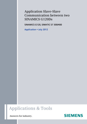
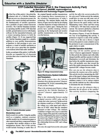
5 Installation and Commissioning5Installation and Commissioning5.1Installing the hardwareThe figure below shows the hardware configuration of the application.Figure 5-1: Hardware setupL1L2L3NPE3AC 400VDC 24VL1L2L3PESINAMICSPM 240-2M L SINAMICSCU 250S-2 PN Siemens AG 2017 All rights reserved33 ENC 79 GND70 AP71 AN72 BP73 BN74 ZP75 ZNSIMATIC S7CPU 1215CPN PNDC 24VM L SIMATIC PanelKTP700(optional)PN PNU2 V2 W2PNMNoteThe setup guidelines for SINAMICS drives and SIMATIC controllers mustgenerally be followed.Positioning with SINA POSEntry ID: 109736845, V1.0,06/201725
5 Installation and Commissioning5.2IP addresses and device namesThe following IP addresses and device names are used in the application example.Subsequent changes can be made at any time.Table 5-1: IP addresses and device namesComponentsDevice nameIP addressSIMATIC S7-1200SIMATIC CPU1215C192.168.0.1SINAMICS G120SINAMICS CU250S192.168.0.2SIMATIC KTP700SIMATIC KTP700192.168.0.10PG/PC-192.168.0.200The network mask is always 255.255.255.0 and no router is used.5.3Download the project to the componentsThe steps listed in the following table show how to load the individual programs ofthe application example into the components. Siemens AG 2017 All rights res
Positioning with SINA_POS Entry ID: 109736845, V1.0, 06/2017 9 G 7 d Table 3-1: Transmission telegram to the drive Address Name Content PZD 1 STW1 Control word 1 PZD 2 POS_STW1 Control word 1 for the basic positioner PZD 3 POS_STW2 Control word 2 for the basic positioner PZD 4 STW2 Control word 2