Transcription
Robotic Cleaner Troubleshooting GuideCopyright 2010 Hayward Industries Inc.
Table of ContentsTigerShark & TigerShark QCImportant safety instructionsPage 1Service ToolsPage 2Filter Removal/Cleaning and Drain FlapsPages 4-6Handle RemovalPage 7Venturi RemovalPage 8Bottom Lid DisassemblyPages 9-10Side Cover RemovalPages 11-12Drive Track and IdlersPages 13-16Power Cord and Motor BoxPages 17-27Wheel Tube Brush and BearingsPages 28-30Using the Scanner ToolPages 31-34Power Supply and Flotation Cord TestingPage 35Basic OperationPages 36-37TroubleshootingPages 38-43
Table of Contents ContinuedSharkVAC & E-VacService ToolsPage44Power SupplyPage45Filter RemovalPages 46-47Filter ReplacementPage48Wheel and Tire RemovalPage49Side Cover RemovalPage50Drive Track and IdlersPage51Main Drive Pulley RemovalPage52Wheel Tube RemovalPage53Wheel Tube BrushPage54Power Cord RemovalPages 55-60Motor Box RemovalPages 61-62Power Supply and Flotation Cord TestingPageTroubleshootingPages 64-6863
Safety!Page 1
Service ToolsPin Removal ToolTorx BitTorque DriverSpanner ToolTorx DriverScannerPage 2
Power SupplyOn/Off Switch - LightedQuick Clean LED(QC Models Only)Power CordFull Cycle Buttonand LED(QC Models Only)Flotation Power Cord ConnectorPage 3
Disassembly – Filter RemovalRemove bottom lid by slidingLH and RH latch towards center.Bottom lid removed providingaccess to filter cartridge assemblyPage 4
Filter RemovalNote the drain flaps, one per side. Notrequired to remove for filter cleaning, butvisually inspect when filter is removed.Filter cartridge removedPage 5
Filter RemovalNote: Elements must be installed with support ribs facing outwardFilter cartridge assemblyNote: Elements can be cleanedby gently spraying with agarden hose.Be careful not to use highpressure or this may damagethe element.Filter elements removedSpring cleanup filterelements. For temporary usein heavy spring cleaning.Page 6
Handle RemovalHandle removal1 screw each endHandle removedNote: Handle is watertight.If water is heard sloshing aroundin handle it must be replaced.Page 7
Venturi RemovalRotate CCW & lift outRemoved, access to impellerPage 8
Bottom Lid DisassemblyBottom lid assembly. Pull upto remove inlet cover.Inlet cover removedPage 9
Bottom Lid DisassemblyInlet flaps, check forfree movement.Inlet flaps removedfor inspection.Page 10
Side Cover RemovalMotor output shaft.Drive end.Motor assemblyPower cordPower cord endNote: Use Torx bit and power driver for removal.Bottom view with bottom lidand filter assembly removed.7 screws each end to removefor side plate removal, drive side.Power cord end, 7 screws.Page 11
Side Cover RemovalScrew removalNote that ‘drive side’ or motor outputside is side oppositeof where power cord enters unit.Side cover removedPage 12
Drive Track & Idler Pulley RemovalDrive SideDrive track removedCheck for missing/broken drivecogs on inner loop of belt and alsofor cracks in belt.Track idler pulley (2/side)Bearings should rotate smoothlyand freely.Note that flange faces inward.Page 13
Main Drive Pulley RemovalNote drive ‘key’ in pulley andhow it mates to the outputshaft drive pin of the motor.Main drive pulley, motoroutput side onlyPage 14
Wheel Tube RemovalCarefully pull wheel tubeaway from other side plate.Roller will slide off track.Both drive tubes removed.Page 15
Drive Track & Idler Pulley RemovalNon-drive SideTrack idler pulleys, (3). Notethis side does not have a keyed drive pulleyat the center pulley since it is opposite themotor drive end. This pulley is simplyan idler pulley similar to the ones to the leftand right.Screw removal, opposite side cover,non-drive side.Side cover removedPage 16
Power Cord & Motor Box RemovalRemove strain reliefcover plate.Plate removed showingstrain relief system.Page 17
Power Cord & Motor Box RemovalUse spanner wrench andTorque driver to removethreaded plug securingpower cord into motor assembly.CCW removal.Threaded plug removedPage 18
Power Cord & Motor Box RemovalGently pull on cord todisconnect and remove from motor.Note that plug has taper on bottom sideto mate with rubber seal taper.Note: Any time seal is removedit is recommended to replacespecial rubber seal.Page 19
Power Cord & Motor Box RemovalCarefully insert pin removal toolinto power cord connector. Pushwires up into connector as faras possible.While holding connector firmly, depressbutton on pin removal tool to removeelectrical connector pin from housing.Page 20
Power Cord & Motor Box RemovalPower cord electrical pinsremoved from connector. Note that whitewire goes on tab side of connector.Connector, seals andwashers removed.Page 21
Power Cord & Motor Box RemovalConnector must be installed with tab onconnector placed in mating hole of motorassembly. The white wire must be insertedon the tab side of the connector.Note the order of the seals and washers.Remember to mate the taper of the sealand threaded plug.Use the Torque driver and spanner wrench to installand tighten the threaded plug. Tighten the threadedplug until you feel the Torque wrench click or slip.Page 22
Power Cord & Motor Box RemovalGently route powercord out from unit.Power cord removed.Page 23
Power Cord & Motor Box RemovalLocation of motor screws when side cover is notremoved. It is possible to remove motor assemblywithout removal of side cover. However, the 7 sidecover screws must be loosened on the motordrive side.Remove 4 motor assemblyscrews 2 from each end.Page 24
Power Cord & Motor Box RemovalWhen removing motor assembly without complete removal of side cover,gently separate motor output shaft from keyed drive gear using a screwdriver.The drive gear will remain in place. Be sure to remove all 4 motor securing screws,2 each side and loosen side cover screws before attempting this.Page 25
Power Cord & Motor Box RemovalRotate motor slightly to remove drive output shaftfrom side of unit, then lift out motor assembly.Page 26
Power Cord & Motor Box RemovalOutput shaft key on motor, mates with drive gear.Motor assembly removed.Note: The motor assembly is a sealed unit andcannot be serviced, only replaced. It does notcontain oil and is water cooled. The impellercan be replaced.Impeller removalPage 27
Wheel Tube BearingsRemove wheel tube from machineRemove 2 smallphillips screwssecuring rollerbearing to tubeBearings should rotate smoothlyand freely.Bearing assembly will slip off tubePage 28
Wheel Tube BrushBrush replacement can be done leaving the machineassembled or broken down. Unsnap the tabs, theserun length wise of the brush.Page 29
Wheel Tube BrushStart in the center of the brush and put the post throughthe hole in the tab with the aid of a pair of needle nosepliers. Pull post slightly till taught then push down on tabuntil it locks into post. Spraying the post with soap andwater sparingly will aid in assembly.Foam rollerPage 30
Using The Scanner ToolPower switch onScanner female endInitializing .Please waitStartup ScreenScanner SetupScanner male endPower cord to cleanerPage 31
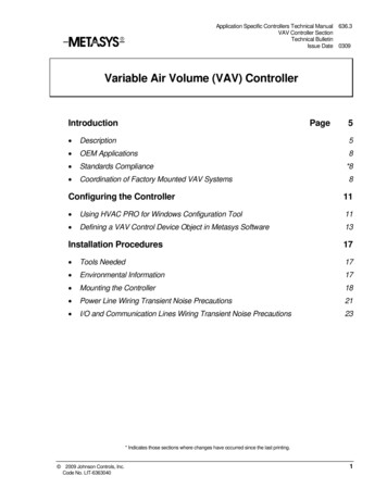
Using The Scanner ToolMotor ON Time4HoursNumber of hours the unit has spentin the 4 hour cleaning cycle mode.Total Cycles Run28CyclesPower ON Time12HoursThe combined total number of hours theunit has spent with the power switch on.Includes both hours accumulated in ‘MotorOn Time’ and hours inactive after the cleaningcycle has been completed.The total number of times the power switchwas turned on to run the unit. This will notnecessarily represent the complete cleaningcycles run.Page 32
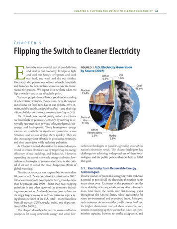
Using The Scanner ToolOut of Water0Times1.2.3.4.5.6.7.Out of Water CausesAttempting to run the unit out of the water/pool.Air trapped in the filter after placing the unit in the water.Bench testing in manufacture or repair.Machine climbing too high above the waterline.Low voltage at power source.Low voltage from use of an extension cord.Worn or defective pump motor, drawing less than 1amp at 24 volts.The number of times the unit has realizeda low load on the pump motor.Pump Overcurrent0TimesPump Over Current Causes1. Debris around the pump impeller. Remove impeller andinspect for hair or grass around pump shaft.2. Defective pump motor. Motor should turn smoothly byhand with only a slight resistance from the shaft seals.Number of times the pump motor has realizedan over load condition. Unit will stop after 3-5seconds in this condition.Page 33
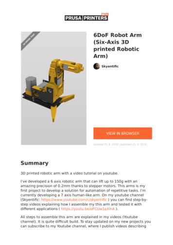
Using The Scanner ToolDrive Overcurrent0TimesDrive Over Current Causes1. Unit caught under a ladder2. Debris caught in traction drivebelt and or pulleys under side cover.3. Riding or standing on unit during operation.4. Defective wheel tube bearings or side cover idler bearings5. Defective drive motor.Number of times the drive motor has realizedan over load condition. Unit will stop after 3-5seconds in this condition.Water Detected0TimesNumber of times the water hascontacted the sensor inside themotor box. Continuouscontact will stop operation of theunit. Severe water damage willcause a ‘Communication Failure’when hooked to the scanner.Page 34
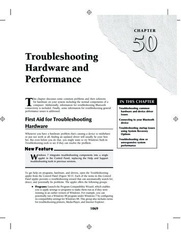
Testing Power Supply & Flotation CordCheckPower andCommunicationConnectionsFailureCommunication Failure Causes1. Damaged power supply, check for 21-25 volts DC2. Water inside power connection to motor box, checkseal at motor box and for breaks in flotation hose3. Damaged flotation cord, check for ohms reading of .4 to .8 ohmsFlotation cord test. Remove cord frommotor box and check ohm’s readingbetween each pin and wire end. .4 to.8 ohm’s is acceptable.Circuit failure between power supply andand the PCB (printed circuit board)in the motor assembly box.DC voltage test on powersupply21 to 25 volts dc is acceptable.The powersupply is not repairable andmust be replacedif defective.Insert voltage probes in pin terminal 1 and 2 andturn on power supply to test.Page 35
Troubleshooting¾Startup Machine will sequence between pump and drive motor for up to 1 minute. During this time the microprocessor is sampling motors for proper electrical load.¾Mapping Sequence At about 2 minutes the machine will begin mapping the immediate section of the pool. Wall climbing will be every other floor pass and the time on the wall climb willbe random. The pattern is not permanently imbedded and will be reconfigured with eachuse of the cleaner.¾Wall Climbing Once in the cleaning cycle the machine will typically perform a wall climb everyother floor pass and vary the amount of time on the wall. At random the machine will perform a free fall from the wall to aid in randomnavigation. The startup of each 4 hour cycle may require up to 30 minutes as the machinemeasures the pool configuration before climbing the walls completely to the water line.Page 36
Troubleshooting¾In Process Mapping As the unit encounters large changes in pool configuration it will revert to themapping process for a few passes to adjust itself to the change in shape. Mapping will take several passes and is undetectable from normal operation.¾Navigation The unit navigates itself primarily by running in a diagonal direction at the water line. This is the key to complete pool coverage.¾Shutdown The machine will shut down after 4 hours for the standard TigerShark. TigerShark QC will shutdown after 90 minutes if the Quick Clean LED isilluminated, or after 4 hours if “Full Cycle” is selected. The power supply will continue to supply low voltage to the unit and the diagnosticmemory will continue to record hours until the power switch is turned off.Page 37
Troubleshooting¾Will not climb wallsFilter Too Dirty to Allow Proper Machine Performance Pool condition is unacceptable for cleaner use. Sweep walls, vacuum pool, balancechemicals and algaecide to an acceptable swimming condition. Resume use ofTigerShark for pool maintenance as often as required. Increase frequency of TigerShark filter cleaning, especially during the initial use.Filter may have to be cleaned 30 minutes to 3 hours in the first few cycles until thepool is in an acceptable condition. Algae on pool walls. Brush walls and chemically treat for algae. Increase frequencyof TigerShark use and filter maintenance. D.E. or sand filter leak. The primary pool filter may leak diatomaceous earth or finesand that can overload the filter. Service and inspect the pool filter system, vacuumthe pool and resume use of the TigerShark for pool maintenance.Page 38
Troubleshooting¾Will not climb wallsPool design or configuration The pool bottom corner design may be too sharp. Some pool designs feature asharp, 90 degree bottom corner. A guideline for the best machine performance is acorner radius similar in contour to a basketball. In a clean pool the machine symptomwill be movement to the wall with repeated bumping and infrequent climbing, ThePVC rollers can be replaced with foam rollers only if a dirty pool condition isruled out. Clean vinyl or tile pool surface is too slick. Replace the PVC rollers with foam rollersonly if a dirty pool condition is ruled out.Machine problem Broken impeller. Inspect and replace it if required. Inspect for tears that may allowobjects to pass through and entangle or damage the impeller. Defective pump motor can be identified by a slow or non-rotating impeller. Replacethe motor box assembly.Page 39
Troubleshooting¾Will not climb wallsConfusion on normal operation The startup of each 4 hour cycle may require up to 30 minutes as the machinemeasures the pool configuration before climbing the walls completely to the waterline. During the 4 hour cycle the machine will randomly re-measure the pool configurationor release itself from the wall. The machine will not climb the walls during this 15-30minute cycle.¾Climbs Too High, Falls off Wall at Waterline, Blows AirBubbles Through the Exit Venturi Above average traction in a clean pool. Install the Restrictor Plate Kit RCX11206 inthe venturi. Inspect bottom lid filter plate gasket and replace if torn or missing. Set handle position at an angle, machine should never operate with the handle in thecenter or straight position. Check water chemical balance.Page 40
Troubleshooting¾Runs only a few seconds or minutes Make sure the machine is submerged in the water. An out of water detection within afew minutes will cause the machine to stop if not completely submerged. Check electrical source for proper voltage. If using an extension cord, test for proper voltage. An extension cord is notrecommended. Check for missing or broken impeller blades. Check for pump impeller obstruction. Check pump impeller for hard rotation and pump motor binding.¾Cord twisting Alternate handle position with each use. Be sure machine is not getting caught on obstructions in the pool such as raiseddrains, in floor cleaning heads, toys, etc.Page 41
Troubleshooting¾No movement but impeller turns Drive motor pin or drive motor is broken possible due to overload during use. Toavoid repeat failure, follow-up with the customer for obstructions in the pool such asa ladder. The Scanner will display a Drive Over Current signal if the machine hasbeen caught on an obstruction. Check for belt or roller obstruction Check for broken impeller Check for missing roller tube bearing screws, 2 per side.¾No movement and no pump discharge Check with the scanner for communication failure, see scanner section to diagnose. Check for impeller obstruction. Check for broken blades. Check electrical source for proper voltage range of 115-125v, including extensioncord if used.Page 42
Troubleshooting¾Debris falls from unit when removed from pool Filter overload, increase frequency of filter cleaning. Large debris blocking intake. Remove large debris from pool before using machine. Drain flaps out of place on bottom lid. Snap flaps back into place. Avoid dropping orthrowing machine into the pool.Page 43
Service ToolsPower Driver (not supplied)Pin RemovalToolTorx DriversT-10 & T-25(not supplied)Torx BitT-20(not supplied)Spanner ToolBelt Installation ToolTorque DriverPage 44
Power SupplyOn/Off Switch - LightedInstallationand CareInstructionsPower CordFlotation Power Cord ConnectorPage 45
Filter RemovalPress Dome Buttonto lift Dome for filter removal.Lift to remove Filter BucketHousingFilter cartridge removedFilter Bucket HousingPage 46
Filter RemovalOpen filter doors by pushing the tabstoward the outside and then pulling up.Note: Elements can be cleaned by gently sprayingwith a garden hose. Be careful not to use highpressure or this may damage the element.Lift filter cartridges out.Spring cleanup filterelements. For temporary usein heavy spring cleaning.Page 47
Filter ReplacementHold both cartridges toward center. Push down cover andpress tab towards fan to lock cartridges in place.Make sure cover snaps in place.Page 48
Wheel and Tire RemovalRemove wheel cap to access screwholding wheel on axel.Unscrew T25 screwRemove wheel from axel. Notice how wheel and axel mate.Page 49
Side Cover RemovalPower cordMotor assemblyImpeller Motor output shaft.Drive end.4 T20 screws each side to removefor side plate removal.Top view with bottom lidand filter assembly removed.Drive side view with cover removed.Page 50
Drive Track & Idler Pulley RemovalDrive SideTrack idler pulleysCheck for missing/broken drivecogs on inner loop of belt and alsofor cracks in belt.Bearings should rotate smoothlyand freely.Note that flange faces inward.Page 51
Main Drive Pulley RemovalNote drive ‘key’ in pulley andhow it mates to the outputshaft drive pin of the motor.Main drive pulley, motoroutput side onlyPage 52
Wheel Tube RemovalRear TubeUnscrew T20 screws from each side of roller.Front TubeCarefully pull wheel tube away fromwheel axels.Page 53
Wheel Tube BrushRemovalBrush replacement can be doneleaving the machine assembled orbroken down. Unsnap the tabs that runlength wise of the brush.ReplacementStart in the center of the brush and putthe post through the hole in the tabwith the aid of a pair of needle nosepliers. Pull post slightly till taught thenpush down on tab until it locks intopost. Spraying the post with soap andwater sparingly will aid in assembly.Page 54
Power Cord RemovalRemove strain relief cover plate.Use spanner wrench and Torquedriver to remove threaded plug.Plate removed showing strain relief system.Threaded plug removedPage 55
Power Cord RemovalGently pull on cord todisconnect and remove from motor.Note that plug has taper on bottom sideto mate with rubber seal taper.Note: Any time seal is removedit is recommended to replacespecial rubber seal.Page 56
Power Cord RemovalPush wires up into connector as faras possible. Carefully insert pin removal toolinto power cord connector.While holding connector firmly, depressbutton on pin removal tool to removeelectrical connector pin from housing.Page 57
Power Cord RemovalPower cord electrical pinsremoved from connector. Note that whitewire goes on tab side of connector.Connector, seals and washers removed.Page 58
Power Cord RemovalNote the order of the seals andwashers. Remember to mate thetaper of the seal and threaded plug.Connector must be installed with tab onconnector placed in mating hole of motorassembly. The white wire must beinserted on the tab side of the connector.Use the Torque driver and spanner wrench to installand tighten the threaded plug. Tighten the threadedplug until you feel the Torque wrench click or slip.Page 59
Power Cord RemovalGently route powercord out from unit.Power cord removed.Page 60
Motor Box RemovalRemove 4 T20 screws securing motor to base.When removing motor assembly without completeremoval of side cover,gently separate motor output shaft from keyeddrive gear using a screwdriver.The drive gear will remain in place. Be sure toremove all 4 motor securing screws.Page 61
Motor Box RemovalRotate motor slightly to remove drive output shaftfrom side of unit, then lift out motor assembly.Note: The motor assembly is a sealed unit andcannot be serviced, only replaced. It does notcontain oil and is water cooled. The impellercan be replaced.Output shaft key on motor, mateswith drive gear.Impeller removalPage 62
Testing Power Supply & Flotation CordCommunication Failure Causes1. Damaged power supply, check for 21-25 volts DC2. Water inside power connection to motor box,check seal at motor box and for breaks inflotation hose3. Damaged flotation cord, check for ohms readingof .4 to .8 ohmsFlotation cord test. Remove cord frommotor box and check ohm’s readingbetween each pin and wire end. .4 to.8 ohm’s is acceptable.Insert voltage probes in pin terminal 1 and 2 andturn on power supply to test.DC voltage test on power supply21 to 25 volts dc is acceptable. The powersupply is not repairable and must be replacedif defective.Page 63
Troubleshooting¾Startup Machine will sequence between pump and drive motor for up to 1 minute. During this time the microprocessor is sampling motors for proper electrical load.¾Mapping Sequence At about 2 minutes the machine will begin mapping the immediate section of the pool. The pattern is not permanently imbedded and will be reconfigured with eachuse of the cleaner.¾In Process Mapping As the unit encounters large changes in pool configuration it will revert to themapping process for a few passes to adjust itself to the change in shape. Mapping will take several passes and is undetectable from normal operation.Page 64
Troubleshooting¾Navigation The unit navigates itself primarily by running in a diagonal direction at the water line. This is the key to complete pool coverage.¾Shutdown The machine will shut down after 2 hours. The power supply will continue to supply low voltage to the unit and the diagnosticmemory will continue to record hours until the power switch is turned off.¾Cleaner flips upside down and continues to run The machine should correct itself and flip upright. Check for water in handle. Replace if necessary. Replace motor.Page 65
Troubleshooting¾Runs only a few seconds or minutes Make sure the machine is submerged in the water. An out of water detection within afew minutes will cause the machine to stop if not completely submerged. Check electrical source for proper voltage. If using an extension cord, test for proper voltage. An extension cord is notrecommended. Check for missing or broken impeller blades. Check for pump impeller obstruction. Check pump impeller for hard rotation and pump motor binding.¾Cord twisting Be sure machine is not getting caught on obstructions in the pool such as raiseddrains, in floor cleaning heads, toys, etc.Page 66
Troubleshooting¾No movement but impeller turns Drive motor pin or drive motor is broken possible due to overload during use. Toavoid repeat failure, follow-up with the customer for obstructions in the pool such asa ladder. Check for belt or roller obstruction Check for broken impeller Check for missing roller tube bearing screws, 2 per side.¾No movement and no pump discharge Check for impeller obstruction. Check for broken blades. Check electrical source for proper voltage range of 115-125v, including extensioncord if used.Page 67
Troubleshooting¾Debris falls from unit when removed from pool Filter overload, increase frequency of filter cleaning. Large debris blocking intake. Remove large debris from pool before using machine. Drain flaps out of place on bottom lid. Snap flaps back into place. Avoid dropping orthrowing machine into the pool.Page 68
1. Damaged power supply, check for 21-25 volts DC 2. Water inside power connection to motor box, check seal at motor box and for breaks in flotation hose 3. Damaged flotation cord, check for ohms reading of .4 to .8 ohms Circuit failure between power supply and and the PCB (printed circuit