Transcription
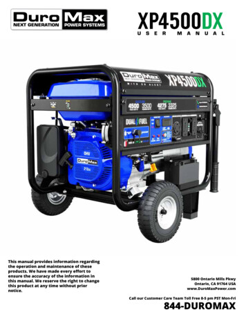
XP4500DXU S E RThis manual provides information regardingthe operation and maintenance of theseproducts. We have made every effort toensure the accuracy of the information inthis manual. We reserve the right to changethis product at any time without priornotice.M A N U A L5800 Ontario Mills PkwyOntario, CA 91764 USAwww.DuroMaxPower.comCall our Customer Care Team Toll Free 8-5 pm PST Mon-Fri844-DUROMAX
CONTENTS1.IntroductionIntroduction . 6General Safety Procedures . 8Carbon Monoxide Safety. 12Unit and Purchase Information . 142.Generator SetupGenerator Components. 16Package Contents. 18Packing Braces . 19Wheel Kit Installation. 20Connect the Battery . 22Adding Oil. 23Adding Gasoline. 24Grounding the Generator . 25High Altitude Operation . 253.Starting the GeneratorChecking the Oil . 28Check the Gas Level . 29Starting the Generator Using Gasoline. 30Starting the Generator Using Propane. 32Starting the Generator Using Recoil Start . 364.Using the GeneratorAC Usage. 40Connecting a Load to the Generator. 42Using the Digital Multimeter. 44
CONTENTS6.Maintenance and CareMaintenance Schedule. 48Maintenance Log . 49Checking the Oil . 50Changing the Oil. 51Cleaning the Air Filter. 52Spark Plug Maintenance. 54Storage and Transportation. 56Specifications. 577.TroubleshootingBasic Troubleshooting . 60Changing / Inspecting the Carbon Brushes . 61Changing / Inspecting the AVR . 63Wiring Diagram . 668.Warranty . 689.Contact Information . 72
THE DUROMAX WAYThe DuroMax Way is more than just a brand, it is our understanding and appreciation of just howimportant power can be to someone without it DUROMAX FOR HOMEElectricity in our home notonly provides comfort butsafety as well. From keepingthe heat or A/C on to keepingour food cold, power isessential to our daily lives.Inevitability when disasterstrikes and we are left withoutpower for a prolonged periodof time, our way of life isput at risk. This is by far themost critical time for reliableportable power.DUROMAX FOR WORKOn the job site, portablepower allows you the abilityto get work done in remotelocations when traditionalpower sources are usuallyunavailable. Equipment liketable saws, sanders, andwork lights are a necessitiesand portable power canplay a critical role in gettinga job done successfully andefficiently.DUROMAX FOR PLAYCamping outdoors in aremote location can get onein touch with nature and allowthem to forget the stress ofthe day-to-day grind. Here,portable power can providecomfort as well as safety. Withportable power, you can keepyour cellphone charged, lightup your campsite, or evenbrew a cup of coffee, all whilebeing miles from civilization.The DuroMax Way is a commitment to excellence. This vision is focused on the quality,reliability, and durability of our products combined with outstanding customer service. Weunderstand that having dependable power whenever and wherever you need it provides comfort,safety, and peace of mind. It is through this philosophy that DuroMax achieves our vision of.6
INTRODUCTIONDuroMax Power Equipment is headquartered in Ontario, California and is the industry’s leader inDual Fuel portable generator technology. In addition to a full assortment of portable generatorsranging from digital inverters to large 15,000-watt portable standby units, our product line includespressure washers, engines, pumps, and accessories.The foundation of our company is built on quality, reliability, durability, and customer service. AtDuroMax our vision is simple, we are committed to Powering Everyone. Anywhere!STOPPlease do not returnto the store.DuroMax representatives are ready to help youwith any questions, concerns, or issues about yournew product. We can guide you through assembly,start up, and how to operate your new generator.We want you to be able to put your new generatorto use right away!CALL US BEFORE YOU CONSIDERRETURNING THE PRODUCT!TOLL-FREE1-844-DUROMAXNotice Regarding EmissionsEngines that are certified to comply with U.S. EPA emission regulations for SORE (Small Off-RoadEquipment), are certified to operate on regular unleaded gasoline and may include the followingemission control systems: (EM) Engine Modifications and (TWC) Three-Way Catalyst (if so equipped).7
GENERAL SAFETY PROCEDURESSAFETY ALERT SYMBOLThe safety alert symbol is used with one of the safety words (DANGER,CAUTION, or WARNING) to alert you of hazards. Please pay attention tothese hazard notices both in this manual and on the generator.Please familiarize yourself with the following safety symbols and words: DANGER: Indicates a hazard that will result in serious injury or death if instructions are notfollowed. WARNING: Indicates a strong possibility of causing serious injury or death if instructions are notfollowed. CAUTION: Indicates a possibility of personal injury or equipment damage if instructions are notfollowed.DANGER: This generator produces poisonous carbon monoxide gas when running. Thisgas is both odorless and colorless. Even if you do not see or smell gas, carbon monoxidemay still be present. Breathing this poison can lead to headaches, dizziness, drowsiness,and eventually death. Use outdoors ONLY in non-confined areas. Keep several feet of clearance on all sides to allow proper ventilation of the generator.WARNING: The exhaust from this product contains chemicals known to the State ofCalifornia to cause cancer, birth defects, or other reproductive harm.WARNING: This generator produces heat when running. Temperatures near exhaust canexceed 150 F (65 C). Do not touch hot surfaces. Pay attention to warning labels on the generator denotinghot parts of the machine. Allow generator to cool several minutes after use before touching engine or areaswhich heat during use.8
GENERAL SAFETY PROCEDURESWARNING: This generator may emit highly flammable and explosive gasoline vapors,which can cause severe burns or even death. A nearby open flame can lead to anexplosion even if not directly in contact with gasoline. Do not operate near an open flame. Do not smoke near the generator. Always operate on a firm, level surface. Always turn the generator off before refueling. Allow generator to cool for at least 2 minutes before removing the fuel cap. Loosencap slowly to relieve pressure in the tank. Do not overfill the gas tank. Gas may expand during operation. Do not fill to the topof the tank. Always check for spilled gas before operating. Empty the gasoline tank before storing or transporting the generator. Before transporting, turn the fuel valve to the off position and disconnectthe spark plug.WARNING: This generator produces a powerful voltage, which can result in electrocution. ALWAYS ground the generator before using it (see the “Grounding the Generator”portion of the “PREPARlNG THE GENERATOR FOR USE”). The generator should only be plugged into electrical devices, either directly or withan extension cord. NEVER connect to a building electrical system without a qualifiedelectrician. Such connections must comply with local electrical laws and codes. Failureto comply can create a backflow of power, which may result in serious injury or deathto utility workers. Use a ground fault circuit interrupter (GFCI) in highly conductive areas such as metaldecking or steelwork. GFCls are available in-line with some extension cords. Do not use uncovered in rainy or wet conditions. Do not touch bare wires or receptacles (outlets). Do not allow children or non-qualified persons to operate.9
GENERAL SAFETY PROCEDURESIn addition to the above safety notices, please familiarizeyourself with the safety and hazard markings on thegenerator.DANGER1.5”DO NOT OVERFILLTHE GAS TANKOVERFILLING CAN RESULTIN A FIRE, EXPLOSION,OR DEATH.10
GENERAL SAFETY PROCEDURESCAUTION HIGH TEMPERATUREDON’TTOUCHEXHAUSTDANGER HOTKEEP SAFE DISTANCEBURN RISKCARBON MONOXIDEDON’TSAFE DISTANCETOUCH11
CARBON MONOXIDE SAFETYCarbon MonoxideGenerators are convenient, but they can also be dangerous. All fuelburning appliances and equipment release a poisonous gas called carbonmonoxide.Carbon monoxide (also known as CO) can be dangerous for humansand pets, even in small amounts, because it blocks oxygen from gettinginto your body. Carbon monoxide poisoning can lead to death in a veryshort time. It is odorless, tasteless and invisible, so you may be exposedwithout knowing it. That is why carbon monoxide is sometimes called“the silent killer.”CO-ALERTDescriptionThe DuroMax CO Alert system was created to protectour customers and their families from dangerous carbonmonoxide. Just like the detector for your home the CO Alerttests the air for to keep you safe and healthy.CO DetectedIf dangerous carbon monoxide levels are detected: The indicator will light red. The engine will shutdown. The engine will not restart for 5 minutes.Maintenance RequiredIf an error in the CO Alert system is detected the indicatorwill light yellow. Please contact DuroMax Service at844-DUROMAX for assistance.12
As the only safe way to use a portable generator, taking yourgenerator outside is absolutely mandatory to keep your familysafe from carbon monoxide. But there’s even more you can do.By educating yourself about all carbon monoxide risks, you’llbe better prepared to protect your family from this colorless,odorless threat. Visit takeyourgeneratoroutside.com for moreinformation.
UNIT AND PURCHASE INFORMATIONSerial NumberSerial NumberThe serial number is located on the engine block, above andto the left of the oil fill.Serial number formatThe serial number will be shown in two parts. The enginemodel, followed by the serial number.Engine Model:Serial Number:STAPLE RECEIPT HEREA purchase receipt may be necessary for warranty parts orservice in the future. If you have a paper receipt, staple ithere for easy reference.If you purchased the unit online, save the email receiptwhere you can access it, and record your details here forconvenience in the future.Purchase Date:Order Number:Retailer Name:14
GENERATOR SETUPProper setup of your generator will get you going as soon as possible while making sure you andyour equipment are safe and cared for.15
GENERATOR COMPONENTS5. Fuel Tank6. Power Panel4. Fuel Valve3. Choke Lever7. Handles8. Battery2. Air Cleaner1. Recoil Start9. Oil Fill and Dipstick1.Recoil Start – Easy pull recoil start to start the engine without the electric start.2.Air Cleaner - A removable, cleanable, oiled, element that cleans the air going into the engine.3.Choke Lever - Restricts the airflow into the carburetor to assist in starting the engine.4.Fuel Valve - On/off valve that allows gasoline to the fuel switch.5.Fuel Tank - All metal 4 Gallon gasoline fuel tank.6.Power Panel - Contains the start switch, plugs, meters, and circuit breakers.7.Handles - Longest handles of any model allow easy movement across any surface.8.Battery - 12V DC battery that powers the electric start system.9.Oil Fill and Dipstick - Use to add or check the oil.10. Propane Inlet - Provides a regulated LPG fuel supply to the engine. (Intended for use with anLPG source of 11 in. H2O or more.)11. Engine Switch – 3 Position switch to “Start”, “Run”, or turn “Off” the generator.12. Low Oil Alert – Will light only if the generator shuts down due to low oil.16
13. Multimeter12. Low Oil Alert11. Engine Switch10. Propane Inlet19. Charging Light14. Power Boost16. GFCI 20A Receptacles15. Circuit Breaker18. CO Alert17. 120/240V 4-Prong Twist Lock13. Multimeter – Displays voltage, hertz, and time running.14. Power Boost – DuroMax exclusive Power Boost doubles the amperage available in “120V Only”for heavy loads like RV air conditioners.15. Circuit Breaker - Protects the panel from overload and short circuits.16. 120v 3-Prong GFCI Receptacles - Use to connect electrical devices that run 120 volt, 60Hz,single-phase, AC current (NEMA 5-20).17. 120/240v 4-Prong Twist Lock - Use to connect electrical devices that run 120 or 240 volt, 60Hz,single-phase, AC current (NEMA L14-30).18. CO Alert - Shuts down the engine in the event of CO buildup.19. Charging Light - Will light when the generator is charging the on-board battery.17
PACKAGE CONTENTSYour generator comes with the items listed below. Please check to see that all of the followingitems are included with your generator.Double-SidedScrew DriverPhillips and slot bladescrewdriver used for generatormaintenance.Oil Funnel w/ hoseUsed to add oil to thegenerator without messy spills.SpannerSpark Plug WrenchAssorted wrenches used ingenerator maintenance andassembly. 10mm/12mm and13mm/15mm.Used in spark plugmaintenance, inspection, andinstallation.Propane Regulator w/HoseUsed provide a regulatedpropane supply to the propaneinlet.Plug EndsPlug heads for the receptaclesfound on the generator areincluded to make or rewireyour own cords. Note: Actual tools may differ in appearance or design from the images shown.18
GENERATOR SETUPStep 1 - Remove Shipping Braces1. Unpacka.Remove the generator from the box.b.Place the largest piece of packing foam on a flat surface.c.Flip the generator upside down on the pad.CAUTION: NEVER attempt this if you have put fuel or oil inthe generator.2. Remove bracesThe shipping braces prevent engine movement duringshipment. Flip the generator over and remove the brightlycolored braces between the motor and the frame, and thewood brace under the generator.Note: Shipping braces can be thrown away.They will not be needed again.19
GENERATOR SETUP (CONTINUED)Step 2 - Wheel Kit Installation (Optional)1. Install support legsa.Secure the support legs to the frame with theprovided lock nuts.2. Install wheel axlea.Insert wheel axle bolts through the frame andsecure with the provided nut and wrenches3. Install wheel axle bracketa.Insert wheel axle bracket bolts through the frameand secure with the provided nut and wrenches4. Install inside wheel washersa.20Place one of the large washers onto both sides ofthe axle behind the wheel.
5. Install wheelsa.Place the wheels onto either side of the axle.6. Install outside wheel washersa.Place the other large washers onto each side of theaxle in front of the wheel.7. Install cotter pinsa.Place a cotter pin through the hole on each end ofthe axle and bend it out to secure the wheels.8. Install handlesa.Attach the handles to the brackets on the frameusing the provided bolts and nuts.b.Flip the assembled generator over onto its wheelsand support brackets. Do not over tighten the handles, it will prevent freemovement.*21
GENERATOR SETUP (CONTINUED)Step 3 - Connect the Battery1. Disconnected on arrivalThe generator battery is disconnected on arrival to preventdischarge or accidental starting in storage and transportation.2. Locate the negative cablea.Locate the negative battery cable above and behindthe battery. One side is connected to ground andthe other end needs to be connected to the battery.b.Route the free end to the negative battery terminal.3. Connect the negative cablea.Push the black rubber boot up the wire to eDSosethe connector.b.Securely connect the free end of the battery cableto the negative battery terminal using the screwand nut from the battery with the screwdriver andwrench from the toolkit.4. Cover the terminala.22Cover the connected terminal with the black rubberboot.
Step 4 - Adding OilThe generator requires engine oil to operate properly. The generator, when new from the package,contains no oil in the crankcase*. You must add the proper amount of oil before operating thegenerator for the first time. This amount is equal to the oil capacity of the engine crankcase:Model NumberXP4500DXEngine Oil Capacity20 fl. oz (0.6L)WARNING: Do not apply engine oils with additives or 2-stroke gasoline engine oils. They don’thave enough lubrication and may shorten the engine’s service life.SAEEngine oil recommended: SAE 10W-30. Viscosity varies withregions and temperatures. Choose your oil viscosity using thechart to the left.3010W-30* A small amount of oil from factory testing may be present onarrival.5W-30-20020-40 -30 -20 -10400601080 100 F203040 CENVIRONMENTAL TEMPERATUREAdd oila.Make sure the generator is on a level surface.b.Unscrew the oil filler/dipstick cap from the engine.c.Using a funnel, add the appropriate amount of oilinto the crankcase. You will know the crankcase isfull when the oil level has reached the lower lip ofthe opening you have just poured the oil into.d.Replace the oil filler cap.WARNING: DO NOT overfill the crankcase. Thismay damage the motor and shorten the overalllife of your generator.23
GENERATOR SETUP (CONTINUED)Step 5 - Adding Gasoline (Optional)Add Gasolinea.Make sure the generator is on a level surface.b.Unscrew gas cap and set aside (NOTE: the gas capmay be tight and hard to unscrew).c.Slowly add unleaded gasoline to the fuel tank. Becareful not to overfill. The fuel gauge on the top ofthe gas tank indicates how much gasoline is in thegenerator gas tank.d.Replace fuel cap and wipe up any spilled gasolinewith a dry cloth.Model NumberXP4500DXGas Tank Capacity4 US Gal. (15L)DANGER1.5”DO NOT OVERFILLTHE GAS TANKOVERFILLING CAN RESULTIN A FIRE, EXPLOSION,OR DEATH.WARNING: Gas can expand. Do not fill the gas tank to the very top. Leave aminimum of 1.5 in open space. Gasoline and gas fumes are highly flammable.Do not fill the tank near an open flame. Always check for fuel spills.IMPORTANT: To ensure that the generator runs smoothly use only FRESH, UNLEADED GAS WITH ANOCTANE RATING OF 87 OR HIGHER. Never use an oil/gasoline mixture. Never use old gas. Avoid getting dirt or water in the fuel tank. The gas can age in the tank and make it hard to start up the generator in the future. Never store generator for extended periods of time with fuel in the tank.
Step 6 - Grounding the GeneratorAttach grounding wirea.Ground the generator by tightening the groundingnut against a grounding wire.b.Connect the other end to a copper or brassgrounding rod that’s driven into the earth.A generally acceptable grounding wire is a No. 12 AWG(American Wire Gauge) stranded copper wire.Grounding codes can vary by location. Please contact a localelectrician to check the grounding regulations for your area.WARNING: Failure to properly ground the generator can result in electrocution.High Altitude OperationAt high altitudes, the standard carburetor air/fuel mixture will be too rich. The performance will decrease,and fuel consumption will increase. A very rich mixture will also foul the spark plug and cause hard starting.Operation at an altitude that differs from that at which this engine was certified, for extended periods oftime, may increase emissions. High altitude performance can be improved by specific modifications to thecarburetor. If you always operate your generator at altitudes above 3,000 feet (900 meters), have a dealerperform this carburetor modification. This engine, when operated at high altitude with the carburetormodifications for high altitude use, will meet each emission standard throughout its useful life. Even withcarburetor modification, engine horsepower will decrease by about 3.5% for each 1,000-foot (300-meter)increase in altitude. The effect of altitude on horsepower will be greater than this if no carburetormodification is made.When the carburetor has been modified for high altitude operation, the air/fuel mixture will be too leanfor low altitude use. Operation at altitudes below 3,000 feet (900 meters) with a modified carburetor maycause the engine to overheat and result in serious engine damage.25
26
STARTING THE GENERATORIf this is not your first time using the generator, there are still steps you should take to prepare itfor operation each time you use it.IMPORTANT: At this point, you should be familiar with the procedures described in the firstportion of this section entitled “GENERATOR SETUP”. If you have not yet read this section, goback and read it now.27
BEFORE YOU START YOUR GENERATORStep 1 - Check the OilCheck the oilThe generator is equipped with an automatic shutoff toprotect it from damage due to low oil. Nonetheless, youshould check the oil level of the engine before each use toensure that the engine crankcase has a sufficient amount.To check the oil level:28a.Make sure the generator is on a level surface.b.Unscrew the oil filler/dipstick cap.c.With a dry cloth, wipe the oil off of the stick on theinside of the cap.d.Insert the dipstick as if you were replacing thecap and then remove it again. There should now beoil on the stick. If there is no oil on the stick, or oilonly at the very end of the stick, you should addoil until the engine crankcase is filled (see “AddingOil” portion of the “Maintenance” section).e.Be sure to replace the cap when finished checkingoil.Model NumberXP4500DXEngine Oil Capacity20 fl. oz (0.6L)
Step 2 - Check the Gas Level (Optional)Check fuel levelIf running the engine on gasoline, check to see that there issufficient gasoline in the fuel tank. The fuel gauge on top ofthe tank will give a rough estimate of the gasoline level. Thegauge will appear white then fill red as the tank is filled.Note: Fuel gauge may not register with less than 1/3fuel tank full.DANGER1.5”DO NOT OVERFILLTHE GAS TANKOVERFILLING CAN RESULTIN A FIRE, EXPLOSION,OR DEATH.WARNING: Gasoline and gasoline fumes are highly flammable. Do not fill the tank near an open flame. ALWAYS allow the engine to cool for several minutes before refueling. DO NOT overfill the fuel tank. Fuel expands when shaken or heated. ALWAYS leave11/2“ space or more at the top of the tank. ALWAYS use fresh fuel or stabilized fuel. Old gasoline (older than 30 days) can causepermanent damage to the fuel system. Always check for fuel spills.29
STARTING THE GENERATORStarting the Generator Using Gasoline1. Shut breaker offThe breaker is located on the right side of the front powerpanel. Flip the breaker down to prevent accidental loadwhen starting the generator.2. Turn gas valve onThe gas valve is located above the recoil start on the bottomof the fuel tank. Rotate the valve counterclockwise to thevertical position to turn on the gas supply.3. Close chokeThe choke lever is located above the air filter to the left ofthe recoil start. Slide the lever to the left to cut the air supplyand allow more gas into the engine to start.4. Start the generatorThe engine switch is located on the left side of the frontpower panel. Flip the switch up to the “START” position.30
5. Allow switch return to RUNWhen the engine starts, allow the engine switch to return tothe “RUN” position.6. Open chokePush the choke to the OPEN position as the engine warms up.CAUTION: LPG must be shut off when using gasoline!CAUTION: Gasoline must be shut off when using LPG!CAUTION: Disconnect all electrical loads from the generator before attempting tostart!WARNING: Operating the starter motor for more than 5 seconds can damage themotor. If the engine fails to start, release the switch and wait 10 seconds beforeoperating the starter again.31
STARTING THE GENERATOR (CONTINUED)Starting the Generator Using Propane1. Turn breaker offThe breaker is located on the right side of the front powerpanel. Flip the breaker down to prevent accidental loadwhen starting the generator.2. Turn the gas valve offThe gas valve is located above the recoil start on the bottomof the fuel tank. Rotate the valve clockwise to the horizontalposition to stop the flow of gasoline to the carburetor.3. Connect propane hoseThe propane inlet is located on the left-hand front panel.Securely connect the propane hose to the inlet.4. Connect propane tankScrew the open ACME nut connection to your propane tankand turn the tank on.32
5. Close chokeThe choke lever is located above the air filter to the left ofthe recoil start. Slide the lever to the left to cut the air supplyand allow more gas into the engine to start.6. Start the generatorThe engine switch is located on the left side of the frontpower panel. Flip the switch up to the “START” position.When the engine starts, allow the engine switch to returnto the “RUN” position.7. Open chokePush the choke to the OPEN position as the engine warms up.8. Turn breaker on and connectThe breaker is located on the right side of the front powerpanel. Flip the breaker up to allow the power to flow to thereceptacles. Connect your devices to the receptacles on thefront panel. Start with the largest loads first.33
STARTING THE GENERATOR (CONTINUED)Starting the Generator Using PropaneWARNING: WHEN USING THE GENERATOR WITH LPG, MAKE SURE THERE IS NOPOSSIBLE IGNITION SOURCE CLOSE TO THE GENERATOR.1. Before using, make sure all of the LPG connectors and hoses are well connected andsealed.2. Connect electrical devices to the generator ONLY after the engine runs smoothly.(There may be remnant gasoline in the carburetor; this can cause unsteady engineperformance for several minutes)3. If the propane gas leaks, shut off the LPG supply first and then quickly unplug or turnoff any electrical devices powered by the unit.4. When stopping the engine, unplug or turn off any electrical devices, turn off the maincircuit breaker and then turn off the LPG supply. After the engine has stopped turn theswitch to the “OFF” position.CAUTION: Disconnect all electrical loads from the generator before attempting tostart!WARNING: Operating the starter motor for more than 5 seconds can damage themotor. If the engine fails to start, wait 10 seconds before operating the starteragain.34
35
STARTING THE GENERATOR (CONTINUED)Starting the Generator Using Recoil Start1. Shut breaker offThe breaker is located on the right side of the front powerpanel. Flip the breaker down to prevent accidental loadwhen starting the generator.2. Select your fuel.If using gasoline, see step 2 on pg. 30. If using propane, seesteps 2 - 4 on pg. 32.3. Close chokeThe choke lever is located above the air filter to the left ofthe recoil start. Slide the lever to the left to cut the air supplyand allow more gas into the engine to start.4. Turn engine switch to RunThe engine switch is located on the left side of the frontpower panel. Press the engine switch to the RUN position.36
5. Pull the recoil startThe recoil start is located on the left side panel next to the airfilter. Pull the recoil handle slowly until resistance is felt, thenquickly pull the recoil handle until fully extended.6. Open chokeAfter the engine has started, push the choke to the OPENposition as the engine warms up.7. Turn breaker on and connectThe breaker is located on the right side of the front powerpanel. Flip
120v 3-Prong GFCI Receptacles - Use to connect electrical devices that run 120 volt, 60Hz, single-phase, AC current (NEMA 5-20). 17. 120/240v 4-Prong Twist Lock - Use to connect electrical devices that run 120 or 240 volt, 60Hz, single-phase, AC current (NEMA L14-30). 18. CO Alert -

