Transcription
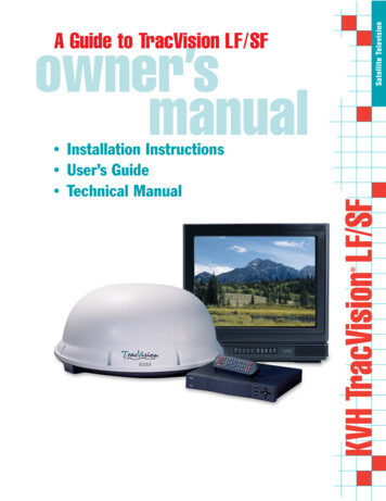
Satellite TelevisionA Guide to TracVision LF/SF Installation InstructionsUser’s GuideTechnical Manual KVH TracVision LF/SFowner’smanual
TracVision LF/SF Owner’sManual Addendum(ECO #s 6768, 6797)The following information applies to Revision C of theTracVision LF/SF Owner’s Manual (KVH Part Number 54-0194).The TracVision LF/SF system now offers a special DISH 500 mode, inwhich the SAT SELECT button switches between the two DISH 500satellites. The following new section explains how to configure and usethis new feature.3.5DISH 500 OperationThe DISH 500 service offers programming on two differentsatellites (Echo 119 and 110). To easily switch between these twosatellites, you will need to configure the system for DISH 500mode, in which the SAT SELECT button selects between just theEcho 119 and 110 satellites.N E T W O R K3.5.1 Configuring the System forDISH 500 ModeTo configure the TracVision system for DISH 500, follow the stepsbelow.1. Turn on your receiver, TV, and TracVisionsystem.2. Using the receiver’s remote control, go to the“Point Dish/Signal Strength” screen (press MENU,6, 1, 1 (on most models)) and select satellite 119 andtransponder 11.3. When the switchplate’s Status indicator fullyilluminates (stops flashing), check the signalstrength meter on the TV. If the meter turns greenand indicates “Locked–Echostar 119,” skip tostep 6.54-0194 Addendum to Rev. C1
4. Press and hold the switchplate’s SAT SELECTbutton for 1 2 second. The Status indicator startsflashing while the antenna searches for anothersatellite.5. When the switchplate’s Status indicator fullyilluminates again, check the signal strength meter.If the meter turns green and indicates “Locked–Echostar 119,” proceed to step 6. If the meter is stillred, repeat step 4.6. Press and hold the SAT SELECT button for fiveseconds, until the Status indicator flashesquickly five times.3.5.2 Switching Between DISH 500 SatellitesOnce the system is configured for DISH 500 mode, you can easilyswitch between the 119 and 110 satellites. Simply press the SATSELECT button to switch from one to the other.IMPORTANT! Switch between satellites only while thevehicle is stationary or, if your system is a TracVision LF, whileyou are driving in a straight line. If you try to switch satelliteswhile the vehicle is turning, the antenna may lock onto thewrong satellite. If this occurs, you will need to reset the system tothe factory default (as described in the next section) then reconfigurethe system for DISH 500 mode (as described in the previous section).3.5.3 Resetting the System to Factory DefaultIf you turn off the TracVisionsystem, move the vehicle, then turnthe system back on, the antennamay not be able to find the correctsatellite upon startup. In this case,you will need to reset the system tothe factory default and thenreconfigure the system forDISH 500 mode.To reset the system to the factory default, in which the antennasearches for a different satellite whenever the SAT SELECTbutton is pressed, follow the steps below.1. Turn off the TracVision system.2. Press and hold the SAT SELECT button whileturning on the TracVision system.3. Continue holding the SAT SELECT button forfive seconds, until the Status indicator flashesquickly five times. When you release the SATSELECT button, the antenna starts up in thefactory default mode.54-0194 Addendum to Rev. C2
Congratulations!You have selected one of the most advanced land-mobile satellitetracking systems available today. KVH Industries’TracVision LF/SF is designed for use with DIRECTV , DISHNetwork , and ExpressVu. This manual provides detailedinstructions on the proper installation, use, and maintenance ofyour TracVision LF/SF system. Before using this manual, besure to check the inside back cover for any addenda, whichmay detail changes to the manual’s information.Throughout this manual, important information is marked foryour attention by these icons:TracVision LF/SF Serial NumberThis serial number will be requiredfor all troubleshooting or servicecalls made regarding this product.Direct questions, comments, or suggestions to:KVH Industries, Inc.50 Enterprise CenterMiddletown, RI 02842 USATel: 1 401 847-3327Fax: 1 401 849-0045E-mail: info@kvh.comInternet: www.kvh.comClick here to go to our state-of-the-artCustomer Support web page.thefastest and easiest way to get all ofyour questions answered!If you have any comments regarding this manual, please e-mailthem to manuals@kvh.com. Your input is greatly appreciated!KVH Part # 54-0194 Rev. C 2003, KVH Industries, Inc.
TracVision and KVH are registered trademarks ofKVH Industries, Inc.DIRECTV is an official trademark of DIRECTV,a unit of GM Hughes Electronics Corporation.DISH Network is an official trademark ofEchoStar Communications Corporation.ExpressVu is a property of Bell ExpressVu, a wholly ownedsubsidiary of Bell Satellite Services.
Table of Contents1Introduction . . . . . . . . . . . . . . . . . . . . . . . . . . . . . . .1-11.1Digital Satellite Television . . . . . . . . . . . . . . . . . . . . . . . . . . . . . .1-11.2System Overview . . . . . . . . . . . . . . . . . . . . . . . . . . . . . . . . . . . .1-11.2.1 TracVision LF/SF Components.1-21.2.2 Integrated Receiver Decoder (IRD) .1-21.3Materials Provided with TracVision LF/SF . . . . . . . . . . . . . . . . .1-21.3.1 Additional Materials Required for TracVision LF/SF Use .1-32Installation . . . . . . . . . . . . . . . . . . . . . . . . . . . . . . . .2-12.1Choosing the Best Location . . . . . . . . . . . . . . . . . . . . . . . . . . . .2-22.2Mounting the Antenna Unit . . . . . . . . . . . . . . . . . . . . . . . . . . . . .2-32.3Connecting System Components . . . . . . . . . . . . . . . . . . . . . . . .2-52.3.1 Connecting the Antenna to the Switchplate .2-62.3.2 Connecting the Antenna to the IRD .2-62.3.3 Sealing the Cable Access Hole .2-82.3.4 Connecting the Switchplate to the IRD .2-82.3.5 Connecting the Switchplate to Vehicle Power .2-92.3.6 Connecting the IRD Ground Wire.2-92.3.7 Installing the Switchplate .2-92.4Activating the IRD . . . . . . . . . . . . . . . . . . . . . . . . . . . . . . . . . . .2-102.5Checking Out the System . . . . . . . . . . . . . . . . . . . . . . . . . . . . .2-102.5.1 Checking Out the System Usingan IRD Data Connection .2-102.5.2 Checking Out the System Withoutan IRD Data Connection .2-122.6Configuring TracVision LF/SF for RemoteSatellite Dish Operation . . . . . . . . . . . . . . . . . . . . . . . . . . . . . .2-133Using Your TracVision LF/SF . . . . . . . . . . . . . . . . . . . . .3-13.1Turning On the System . . . . . . . . . . . . . . . . . . . . . . . . . . . . . . . .3-13.2Tracking the Correct Satellite . . . . . . . . . . . . . . . . . . . . . . . . . . .3-354-0194 Rev. Ci
3.2.1 Using the IRD for Satellite Selection .3-33.2.2 Using the Switchplate for Satellite Selection .3-33.2.2.1The Status Indicator . . . . . . . . . . . . . . . . . . . . . . . . . . . .3-43.3Turning Off the System . . . . . . . . . . . . . . . . . . . . . . . . . . . . . . . .3-43.4Watching Television . . . . . . . . . . . . . . . . . . . . . . . . . . . . . . . . . .3-44Troubleshooting . . . . . . . . . . . . . . . . . . . . . . . . . . . . .4-14.1Causes and Remedies for Common Operational Issues . . . . . .4-14.1.1 Blown Fuse or Improper Wiring .4-24.1.2 Dew or Rain Pooling on Dome .4-24.1.3 Satellite Signal Blocked .4-24.1.4 Satellite Coverage Issue.4-34.1.5 Vehicle Turning During Startup (TracVision LF only).4-34.1.6 Incorrect or Loose RF Connectors .4-34.1.7 Type of Multiswitch Used .4-34.1.8 Stationary Use Only (TracVision SF only) .4-34.2IRD Troubleshooting . . . . . . . . . . . . . . . . . . . . . . . . . . . . . . . . . .4-44.2.1 IRD Wiring .4-44.2.2 AC Power Fluctuating .4-44.2.3 No IRD Data Connection.4-44.2.4 EchoStar IRD Activation Check.4-44.2.5 Failed IRD Status Check .4-54.2.6 IRD Faulty.4-5ii4.3Antenna Gyro and LNB Faults . . . . . . . . . . . . . . . . . . . . . . . . . .4-64.4Computer Diagnostics . . . . . . . . . . . . . . . . . . . . . . . . . . . . . . . .4-64.5Maintenance Port Parser Commands . . . . . . . . . . . . . . . . . . . . .4-75Maintenance . . . . . . . . . . . . . . . . . . . . . . . . . . . . . . .5-15.1Warranty/Service Information . . . . . . . . . . . . . . . . . . . . . . . . . . .5-15.2Preventive Maintenance . . . . . . . . . . . . . . . . . . . . . . . . . . . . . . .5-15.3Replaceable Parts . . . . . . . . . . . . . . . . . . . . . . . . . . . . . . . . . . . .5-25.4Field Replaceable Unit Procedures . . . . . . . . . . . . . . . . . . . . . .5-3
5.4.1 PCB Removal and Replacement.5-55.4.2 Antenna Gyro Assembly (TracVision LF only).5-65.4.3 Antenna LNB Replacement .5-85.5Preparation for Shipment . . . . . . . . . . . . . . . . . . . . . . . . . . . . .5-10Appendix ASystem SpecificationsAppendix BComprehensive System Wiring DiagramAppendix CSwitchplate TemplateAppendix DEchoStar IRD Activation ProcedureAppendix EStartup Data SequencesAppendix FMaintenance Port Parser Commands54-0194 Rev. Ciii
Introduction1Introduction1.1Digital Satellite TelevisionDIRECTV , DISH Network , and ExpressVu systems transmitdigital audio and video data from land-based transmitters to asatellite “parked” above the equator. Each satellite relays thesignals in spot beams covering the continental United States.TracVision LF/SF automatically identifies, locks onto, andreceives signals from the appropriate satellite. TracVision SF isdesigned for stationary use only; TracVision LF works while yourvehicle is at rest and in motion.1.2System OverviewKVH offers an upgrade kit (KVHPart #02-1026) that adds in-motiontracking capability to theTracVision SF, allowing you toreceive satellite signals while onthe move.A complete satellite TV system includes the TracVision LF/SFconnected to an IRD (satellite TV receiver) and a television set. Adesktop or laptop computer is used to conduct diagnostics. Thecomplete system is illustrated in Figure 1-1. System specificationsand a wiring diagram are provided in Appendices A and B,respectively.Figure 1-1TracVision LF/SF SystemConfigurationTracVision AntennaRadome11-16 Volts DC2.5-3.5 AmpsSwitchplateBaseplateData/PowerData (optional)RF2TV 2Satellite Receiver 2VehiclePowerPC MaintenanceRF1Satellite Receiver 1TV 1Laptop PCOptions Purchased Separately54-0194 Rev. C1-1
A Guide to TracVision LF/SF1.2.1 TracVision LF/SF ComponentsThe antenna unit includes the antenna positioning mechanism,signal front end, power supply and control elements. Theantenna is a parabolic dish mounting a dual-output low noiseblock (LNB) converter with built-in preamplifier. A molded ABSradome encloses the baseplate and is secured in place withstandard fasteners. Connectors on the back of the baseplate jointhe power, signal, and control cabling from units inside thevehicle.1.2.2 Integrated Receiver/Decoder (IRD)On-screen messages are notavailable with a DISH Network IRD.The IRD (purchased separately) receives satellite signals from theantenna unit for signal decoding, processing, and channelselection, and sends the signals to the TV set for viewing. Inaddition, messages can be sent from the IRD to the antenna unitand messages can be received from the antenna unit for displayon the television screen. The IRD also provides the interface forthe user to activate authorization for reception. Please refer to theUser’s Manual provided with your selected IRD for completeoperating instructions.1.3Materials Provided withTracVision LF/SFTable 1-1 lists the units, cables, and materials packed in theTracVision LF/SF package by name and KVH part number.Table 1-1TracVision LF/SF Packing ListCables for the TracVision LF/SF arestored beneath the antenna unitduring shipping.1-2ComponentKVH Part No.Antenna Unit (TracVision LF)01-0225-15Antenna Unit (TracVision SF)01-0225-14RF Cable (28 ft)*32-0417-28Data/Power Cable (28 ft)*32-0730-28Kitpack**72-0120Installation and Operation Manual54-0194* RF and data/power cables may be supplied separately.** A complete listing of kitpack contents is provided in Table 2-2.
Introduction1.3.1 Additional Materials Required forTracVision LF/SF UseTo make full use of your new TracVision LF/SF and receivesatellite TV, you will need to provide/purchase the following: Television Appropriate IRD for your selected satelliteTV service54-0194 Rev. CYou can purchase and/or activatean IRD directly from KVH! Call KVHat 1-888-584-4163 for details.1-3
Installation2InstallationTracVision LF/SF is designed for simple installation and setup.Just follow these easy steps:StepRefer to Section.1.Choose the antenna location2.12.Mount the antenna unit2.23.Connect the system components2.34.Activate the IRD2.45.Check out the system2.5Tools and Materials Required Electric drill 3 #2 Phillips and #0 flat tip screwdrivers Silicone sealant or RTV 7 Adhesive suitable for specific roof constructionand materials (e.g., Liquid Nails) Rivet gun and 3 16"-rivets (or other fastener suitablefor specific roof construction) (Recommended) PC with terminal emulationsoftware such as PROCOMM or WindowsTerminal or Hyperterminal and a DB9 (male-tofemale) PC data cable 16"-drill bit and 3 4" hole saw and auger bitTable 2-1Installation ProcessPlan the entire installation beforeproceeding! Take into accountcomponent placement, cablerunning distances between units,and accessibility to the equipmentafter installation. 16"-open end wrenchKitpack ContentsWhile some DIRECTV IRDsoffer on-screen messages, it isrecommended that a PC beavailable for all installations ofDIRECTV, EchoStar, andExpressVu.Table 2-2 lists the materials provided in the kitpack.PartQty.KVH Part No.Switchplate Assembly102-1236-01Tie-wraps522-00133 8" Hole Plugs219-0282-06RJ11 Handset Cable132-0724-25Clam Shell Ventilator119-0230#6 x 3 4" Thread-forming Screws514-0298-12IRD Ground Wire (50 ft)132-0583-5054-0194 Rev. CTable 2-2Kitpack Contents2-1
A Guide to TracVision LF/SF2.1Choosing the Best Location Since the TracVision antenna requires a clear viewof the southern sky to receive satellite signals, theideal antenna site has an unobstructed view of thehorizon/satellite all around. Keep the antenna clear of any obstructions on theroof (e.g., air conditioners). The antenna requires a15º to 75º look angle to receive satellite signals.Figure 2-1Antenna BlockageBlocked!TracVision AntennaAir ConditionerVehicle Roof Consider the location of the antenna relative to thelocation of any equipment or necessary wiringwithin the vehicle. Be sure to mount the antenna on a horizontalsurface with a minimum roof (or other mountingsurface) radius of 250". In other words, whenplaced flat on the mounting surface, the mountingplates should be less than 7 16" above the mountingsurface (see Figure 2-2). Any larger gap will warpthe baseplate and seriously damage the antenna.Figure 2-2Maximum Mounting Surface Slope7 "162-2Maximum Gap
Installation2.2Mounting the Antenna Unit1. Make sure that you have chosen a suitablemounting location based upon the guidelines inSection 2.1, “Choosing the Best Location.”2. Remove the antenna unit from its shipping carton.3. At the bottom of the antenna baseplate, cut thetie-wrap and pull it out of the baseplate. Then sealthe two holes with the plugs provided in thekitpack. The tie-wrap secures the antenna’s LNBfor shipping (as shown in Figure 2-3). Once youremove this shipping restraint, be sure to handlethe antenna unit with care to avoid damage.Always lift the antenna unit by thegray baseplate, never by theradome!Figure 2-3Removing the Shipping RestraintShipping Restraint (Tie-wrap)4. Position the antenna unit in the desired locationon the centerline of the vehicle with the antenna’sforward mounting plate arrows facing the front ofthe vehicle. The proper orientation is illustrated inFigure 2-4.Once you remove the shippingrestraint, handle the antenna unitcarefully. Improper handling maydamage the unit.Figure 2-4Proper Orientation ofthe Antenna UnitVehicleCenterlineBaseplateConnectorsVCe ehicnte lerlineFront ofVehicleTop ViewMounting Plate(1 of 4)FroVe nt ofhicleSide ViewForward MountingPlate Arrows54-0194 Rev. C2-3
A Guide to TracVision LF/SF5. Using the four mounting plates as templates, drill20 3 16" holes through the roof of the vehicle.6. Apply construction adhesive to the bottom of theantenna’s four mounting plates. If using a liquidconstruction adhesive, apply beads to themounting plates in a zig-zag pattern.If the roof’s mounting surface is notperfectly flat as KVH recommends,make sure the baseplate does notwarp when you attach theantenna’s mounting plates. Refer toSection 2.1, “Choosing the BestLocation,” for further details.2-47. Attach the mounting plates to the roof using3 16"-diameter rivets (or appropriate fasteners). Sealall rivet heads and edges with silicone.8. Mark a location on the roof for the cable accesshole to permit convenient cable access to theantenna’s baseplate connectors. Drill the 3 4" cableaccess hole in the vehicle’s roof.
Installation2.3Connecting System ComponentsThe following sections provide instructions for properly wiringthe antenna unit to the components inside the vehicle.Locating the SwitchplateBefore running cables, you need to determine the location for theTracVision LF/SF switchplate.1. The switchplate should be installed in a dry, flatlocation within reach of the cables that willconnect to the antenna unit.2. Once you’ve decided on a suitable location, createa panel cutout in the mounting surface. Figure 2-5illustrates the mounting dimensions and a full-sizetemplate has been provided in Appendix C. Allconnecting cables will be routed through thiscutout.2"Figure 2-5Switchplate Cutout Dimensions2.5"Figure 2-6 shows the antenna unit’s baseplate connectors.Figure 2-7 on the following page shows the switchplate’sconnectors. Refer to these figures when connecting cables to theantenna unit and the switchplate.Figure 2-6Antenna Baseplate ConnectorsRF254-0194 Rev. CData/PowerRF12-5
A Guide to TracVision LF/SFFigure 2-7Switchplate ConnectorsInput Power( 12 VDC)GroundSwitchplate MountingHole (1 of 2)RJ11 Jack(Data Cable to IRD - Optional)Data/Power ConnectorMaintenance Port(DB9 Connector)2.3.1 Connecting the Antenna to theSwitchplate1. Connect one end of the antenna data/power cableto the antenna’s data/power connector and lock inplace (see Figure 2-6).2. Route the other end of the data/power cable downthrough the cable access hole in the vehicle’s roofand out through the switchplate panel cutout.KVH recommends the use ofRG-6 or RG-11 (75 ohms) cablefor RF wiring. Use of non-RG-6or RG-11 (75 ohms) cables willresult in degraded performance.The KVH warranty does not coverdegraded performance due toimproper wiring.When shipped from the factory, theantenna’s RF connectors areprotected with caps. Leave the capinstalled on the RF2 connectorunless you are going to connect asecond RF cable to theTracVision LF/SF.2-63. Connect the data/power cable to the switchplate’sdata/power connector and lock in place (seeFigure 2-7).2.3.2 Connecting the Antenna to the IRD1. Route an RF cable up through the roof’s cableaccess hole.2. Connect the RF cable to the antenna’s RF1connector (see Figure 2-6). Once the cable issecurely connected, loosen the sealing nut at thebase of the RF1 connector and tighten it onto theend of the RF cable.3. Connect the other end of the RF cable to the IRD’sSATELLITE IN connector.
InstallationInstalling Two IRDs and TVsTo connect a second TV and IRD to the TracVision LF/SF system,you must connect a second RF cable to the antenna’s RF2connector (see Figure 2-6). Route the other end of the RF cabledown into the vehicle and connect it directly to the second IRD.Connecting Three or More IRDs and TVsTo install three or more IRD/TV pairs, an active multiswitch(Channel Master model 6214IFD or equivalent) must be placedbetween the antenna unit and the IRDs. Figure 2-8 illustratestypical wiring arrangements for multiple IRDs. If more than fourIRDs are required, contact KVH for additional wiringinstructions. Mount the multiswitch unit in accordance with themanufacturer’s instruction sheet.TracVision IRD Data CableConnector on Switchplate (Optional)TracVision RF ConnectorsFigure 2-8Installing Three or Four IRDsUsing an Active MultiswitchRF1RF2DC PowerDC InRHCP 13VVHF/UHFLHCP 18VMultiswitchOut 1IRD #1Out 2IRD #2Out 3IRD #3Out 4IRD #4If you are connecting multiple IRDs,attach the data cable to the masterIRD. The master IRD must remainon for the secondary IRDs tofunction properly.1. Connect the RF cable tagged “RF1” to themultiswitch input labeled “LNB RHCP 13V.”2. Connect a second RF cable to the multiswitchinput labeled “LNB LHCP 18V.”3. Connect the multiswitch outputs to individual IRDinputs. Use RG-6 cable terminated withF-type connectors for all RF connections.54-0194 Rev. C2-7
A Guide to TracVision LF/SF4. Terminate all unused output connectors with75 ohm DC blocks (Channel Master #7184, RadioShack #15-1259 or equivalent).2.3.3 Sealing the Cable Access HoleOnce the RF and data/power cables are connected to theantenna, you need to seal and cover the cable access hole toprotect against leakage.1. Completely seal the cable access hole with siliconesealant or RTV.Figure 2-9Installing the Clamshell Ventilator2. Install the clamshell ventilator, supplied in thekitpack, over the cable access hole using three ofthe supplied #6 screws (see Figure 2-9).#6 ScrewsClamshellVentilatornisioacVrTTo nnaeAntRF & Data/PowerCablesCable Access Hole(in Roof of Vehicle)2.3.4 Connecting the Switchplate to the IRD(Optional)EchoStar IRDs cannot beconnected to the switchplate dueto incompatibility. Satelliteselection must be done manuallythrough the switchplate’s SATSELECT button.The switchplate includes an RJ11 jack for connecting the systemto an IRD’s low-speed data port. This allows a compatibleDIRECTV IRD to communicate with the antenna for automaticsatellite selection. Without this data connection, you will need tomanually select the satellite using the switchplate’s SAT SELECTbutton (see Section 3.2, “Tracking the Correct Satellite,” for details).1. Connect one end of the supplied data cable (astandard RJ11 telephone handset cord) to theswitchplate’s RJ11 jack (see Figure 2-7).2. Route the other end of the data cable to the IRDand connect it to the IRD’s low-speed data port.2-8
Installation2.3.5 Connecting the Switchplate toVehicle PowerThe switchplate must be connected to a 12 VDC, 2.5-3.5 amppower supply to operate.1. Disconnect vehicle power by removing theappropriate vehicle fuse.2. Run a cable from vehicle’s power (11-16 VDC) outthrough the switchplate panel cutout.3. Connect the power cable to the switchplate’spower terminals as shown in Figure 2-7.Before connecting the antenna unitto vehicle power, remove theappropriate vehicle fuse to preventa short circuit. Replace the fuseafter the connection to vehiclepower is complete.2.3.6 Connecting the IRD Ground WireA grounding wire has been provided to connect your IRD to asuitable ground and protect the system. Attach the groundingwire to any suitable screw on the rear panel of the IRD with agood contact with the IRD chassis. The other end should beconnected to a suitable ground, ideally the ground connector onthe switchplate (see Figure 2-7).2.3.7 Installing the SwitchplateAfter completing the switchplate wiring, you need to install theswitchplate itself.1. Carefully fit the switchplate assembly into thepanel cutout (made in Step 2 of Section 2.3,“Connecting System Components”) until theswitchplate is flush to the mounting surface.2. Secure the switchplate to the mounting surfaceusing the two supplied #6 thread-forming screws.3. Reinstall the vehicle fuse removed in Step 1 ofSection 2.3.5, “Connecting the Switchplate to VehiclePower.”54-0194 Rev. C2-9
A Guide to TracVision LF/SF2.4Activating the IRDKVH makes it easy to activate your IRD. Just call KVH at1-888-584-4163 and ask for IRD Activation (Monday - Friday,8:30 a.m. - 5:00 p.m. EST). For other options, please refer to theuser manual that accompanied your IRD.Note that EchoStar IRDs that have not been activated within severalmonths of manufacture require additional steps to complete the process.Refer to Appendix D for complete details.2.5If a need arises to paint theradome, ONLY use non-metallicautomotive paint to avoiddegrading the RF signal strengthand the reception quality.Checking Out the SystemIf the system is connected to an IRD’s low-speed data port (via anRJ11 cable from the switchplate), follow the procedure inSection 2.5.1, “Checking Out the System Using an IRD DataConnection.” If the system is not connected to an IRD’s low-speeddata port, follow the procedure in Section 2.5.2, “Checking Out theSystem Without an IRD Data Connection.”2.5.1 Checking Out the System Using an IRDData ConnectionTurn on the IRD and press the switchplate’s POWER button topower up the TracVision LF/SF system. Observe messages onyour TV screen to verify proper operation. Some messagesoriginate in the IRD, others are generated in theTracVision LF/SF circuits.All IRDs are susceptible to ACpower fluctuations that can result inthe IRD locking up and requiring areset. Refer to Section 4.2, “IRDTroubleshooting,” for a solution tothis issue.2-10Depending on your choice of satellite TV service and IRD, thesystem may display several text messages on the televisionscreen to aid in monitoring TracVision LF/SF performance. Thesemessages are not displayed when the IRD is displaying theSignal Strength Meter on the TV screen. The messages and theirmeanings are described in Table 2-3 on the following page.
InstallationMessageDefinitionKVH TracVisionDisplays for 5 seconds at startupSoftware VersionCurrent software versionAlternates with “KVH TracVision”InitializingSystem initializingSearch Mode 1Antenna unit in Search Mode 1Search Mode 2Antenna unit in Search Mode 2Search Mode 3Antenna unit in Search Mode 3ReacquisitionSystem is reacquiring the satelliteRF Signal ErrorRF signal detector has no signal at inputAZ Motor ErrorFault detected in azimuth drive subassemblyEL Motor ErrorFault detected in elevation drive subassemblyAnt Gyro Error(TracVision LF only)Fault detected in antenna gyro assembly, ORantenna gyro failed to initialize properlybecause vehicle was turning during the60-second startup and initialization periodfollowing power-upCable UnwrapSystem in process of unwrapping cableTable 2-3TracVision LF/SF OperationalMessagesThe DISH Network and somenewer IRDs (e.g., the Sony A50)give priority to internal IRDmessages rather than on-screenmessages. KVH recommends thatthe maintenance port be used toread installation-related messageson a PC (see Section 2.5.2,“Checking Out the System Withoutan IRD Data Connection”).Differences among IRD low-speed data ports may result indifferent message formats, and some messages may not bedisplayed on the television screen. DIRECTV messages you maysee are listed in Table 2-4.MessageDefinitionSearching for satellite –please stand byThe IRD is powered up anddoesn’t detect the satellite signal.Searching for program guide –please stand byThe system has found the satellite,but has been turned off for morethan approximately four hours. Thismessage appears for about10 seconds.Table 2-4DIRECTV On-screen MessagesRefer to your DIRECTV User’s Manual for specific messagesdisplayed by your system.54-0194 Rev. C2-11
A Guide to TracVision LF/SF2.5.2 Checking Out the System Without an IRDData ConnectionTo ensure that the system is configured and operating properly,you will need to check the data provided in the system’s startuproutine.To do so, you need to connect a PC to the antenna baseplate’smaintenance port. The diagnostics procedure requires terminalemulation software such as PROCOMM or Windows Terminal orHyperterminal. Use the settings appropriate to your application.1. Connect one end of a PC data cable to themaintenance port connector on the switchplate(see Figure 2-10). To access this connector, you mayneed to remove the switchplate from the mountingsurface. Connect the other end to the serial port onthe PC (a 9-pin/25-pin connector adapter may beneeded for some PCs).Figure 2-10Switchplate Maintenance PortFigure 2-11PC Data Cable DB9 ConnectorMaintenance Port(DB9 Connector)2. Open the terminal emulation software andestablish the following settings: 9600 baud no parity 8 data bits 1 start bit 1 stop bit no flow control2-12
Installation3. Press the switchplate’s POWER button to applypower to the TracVision LF/SF system and waitfor the system to fully initialize. Data should bescrolling on the PC d
TracVision LF/SF Owner's Manual Addendum (ECO #s 6768, 6797) The following information applies to Revision C of the TracVision LF/SF Owner's Manual (KVH Part Number 54-0194). The TracVision LF/SF system now offers a special DISH 500 mode, in which the SAT SELECT button switches between the two DISH 500 satellites.