Transcription
Rectangular Zero Clearance Grease DuctModel DWGD-RZ Rectangular Grease Duct Factory Built Double-Wall Zero Clearance Fire Resistive EnclosureInstallation InstructionsTested to: UL1978/ULCS662 UL2221/ULCS144 ULC/S115 ASTM E814Keep these instructions for future reference.For Technical Support or more product information please contact us at 678-388-2740 or visit our website atwww.jeremiasinc.com1Jeremias INSTALL RZ Rev:9/22/2021
INDEXPg.33333444444455567DescriptionSECTION 1 – GENERAL INFORMATIONImportant NoticeIntroductionListings / Codes & AuthoritiesInstallation ConsiderationsMixing Systems & PartsDuct Size & SlopeCleanouts, Drains & Grease TrapsWash down & Fire SuppressionReceiving InspectionTypical Component LocationsFreight DamagePart Identification & Product Code KeySuggested Tools, Equipment & HardwareSafety NoticeClearances & Additional EnclosuresJoint Assembly8889999101111SECTION 2 – SUPPORT & GUIDINGDuct WeightVertical Support Spacing & LimitsLateral Guide SpacingHorizontal Support SpacingFull Angle Support (FAS)Guy Attachment Plate (GAP)Plate Support Assembly (PLS)Full Support Assembly (FSA)Wall Brackets (WBR)12121212121213131313131313SECTION 3 – DUCT SECTIONS & FITTINGSDuct SectionsStraight Sections (STR)Elbow (E)Tee (90T)Wye Tee (WYE)Fan/Hood Adapter Assembly (FAA)Access Panel Section (APS)Open Top Closure (OTC)Rain Cap (RCS)Increasers & ReducersSingle & Double-Wall AdaptersTransition to Round Start & EndPg.14141516161616DescriptionSECTION 4 – THIMBLES, PENETRATIONS, FIRESTOPFloor Penetration Assembly (FPA)Wall Penetration Assembly (WPA)Non-Fire Rated PenetrationsFinishing Plate (FPL)Flashing (FLS)Counter Flashing (CFL)17171717SECTION 5 – FINISHING, INSPECTION & MAINT.Final CheckImportant NoticeMaintenance19WARRANTY2Jeremias INSTALL RZ Rev:9/22/2021
SECTION 1 – GENERAL INFORMATIONIMPORTANT:These instructions must be followed in all details. Failure to do so may result in a hazardous installation. Contact Jeremias Inc. if there are anyquestions regarding these instructions.IntroductionModel DWGD-RZ grease ducts are suitable for the removal of smoke and grease laden vapors from commercial, industrial, institutional, and similarcooking applications where continuous operating temperatures are 500 F (260 C) or less and for intermittent temperatures not exceeding 2000 F(1093 C). Model DWGD-RZ grease ducts are intended to be part of a complete grease duct system which connects the hood or grease extractorwith the outdoors by means of an exhauster or blower system.ListingsJeremias Model DWGD-RZ grease ducts are listed by Intertek as a “zero clearance grease duct enclosure assembly” and as “Grease Ducts forRestaurant Cooking Appliances” when installed in accordance with its Intertek listings, these instructions, and the National Fire ProtectionAssociation’s standard NFPA 96 “Standard for Ventilation Control and Fire Protection of Commercial Cooking Operations,” International MechanicalCode, Uniform Mechanical Code, or other local codes.Model DWGD-RZ has been tested in accordance with the procedures and methods set forth by: UL 2221 /ULC S144 (Tests for Fire Resistive Grease Duct Enclosure Assemblies/Standard Method of Fire Resistance Test-Grease DuctAssemblies) UL 1978/ULC S662 (Standard for Grease Ducts/Standard for Factory-Build Grease Ducts),Model DWGD-RZ with stainless steel liner is qualified as an alternate to a 2-hour rated fire resistive shaft enclosure; eliminating, in most applications,the requirement for a separate fire resistive enclosure.Codes & AuthoritiesInstallation must be made in accordance with local and national code requirements. Follow these instructions carefully and contact local building andfire officials about restrictions and installation inspection in your area. Refer to NFPA 96 (Standard for Ventilation Control and Fire Protection ofCommercial Cooking Operations) and additional NFPA standards as required.Installation ConsiderationsFollow Jeremias’s written installation instructions carefully. Each part of the grease duct system must be installed correctly. Improper or lack ofinstallation of required parts may result in the improper function of the grease duct system.The grease duct layout should be carefully planned to allow adequate space for assembly, installation of supports, connection of support framing,access for cleanouts, accommodate standard fitting dimensions, rough openings for penetrations, etc. Do not assume all equipment producingsmoke or grease laden vapors within a facility can be exhausted with a single grease duct system. Consult a grease duct design professional asrequired.One prime coat and finish coat of appropriate heat resistant paint is recommended on exposed installations which are subject to routine cleaning(e.g. kitchen area) and wherever exposed to the weather when the outer shell of components or accessories is constructed from aluminized steel.Sealing of draw bands, overlapped or butted seams, etc. with an appropriate sealant is recommended on exposed installations which are subject toroutine cleaning (e.g. kitchen area) and wherever exposed to the weather in order to avoid moisture from entering the space between the greaseduct shell and liner.3Jeremias INSTALL RZ Rev:9/22/2021
Mixing Systems & PartsDo not connect a grease duct system with any other building ventilation or exhaust system. Do not connect parts from other grease ductmanufacturers with Model DWGD-RZ components without the expressed consent of Jeremias.Components from other Jeremias product lines, (for example Model DWFL), may be mixed with Model DWGD-RZ components to complete a greaseduct system as long as: clearances, limitations, codes, etc. are followed. Contact Jeremias for more information concerning product lines which arelisted for use as grease ducts.DWGD-RZ systems are intended to be installed as a complete system without the use of other manufacturer or field fabricated components.However, Jeremias recognizes the occasional requirement for a where systems must be mixed duct due to space constraints at certain locations in asystem, or when making modifications or additions to an existing grease duct. In such a case, it is permissible to transition to and from ModelDWGD-RZ Grease Duct to a code compliant, rectangular or round, welded steel grease duct and back again. In such a case, Jeremias willmanufacture and supply a custom single wall stainless steel transition, meeting code thickness requirements, that permits field welding to or from thefield welded duct section(s). Maintain the minimum air space to combustibles of 18” with these custom transitions. Follow NFPA-96 regardingmethods for reduced clearances for these single wall custom transitions as well as the field fabricated grease ducts.Duct Size & SlopeMechanical codes and good practice require that slope (back to a grease reservoir or kitchen hood) be created to prevent pooling of grease withinhorizontal portions of grease duct systems. Model DWGD-RZ grease ducts must be installed accordingly to comply with the requirements asdescribed in order to maintain a listed installation. UL 2221 standard (Tests for Fire Resistive Grease Duct Enclosure Assemblies) states that thesegrease ducts must comply with requirements as set forth by UL 1978 (Standard for Grease Ducts), NFPA 96 (Standard for Ventilation Control andFire Protection of Commercial Cooking Operations), and the International Mechanical Code. Model DWGD-RZ grease ducts should be installed at aslope not less than 1/8” vertical rise in 12” horizontal run toward the hood or toward a grease reservoir. Where horizontal ducts exceed 75 feet inlength, the slope shall be not less than ½” vertical rise in 12” horizontal run. Most Model DWGD-RZ components will permit a small amount of slopeas the system is being installed. However, some installations may require elbow / transition type pieces to allow for proper orientation of fittings atthe vertical risers prior to and after long horizontal runs. It is also acceptable for ducts to have staggered sloped (e.g., uphill to a peak point, thendownhill to a valley point), the distance between a valley point and peak point must follow the limitations above and every valley must allow forgrease drainage (i.e., a hood or reservoir). Contact Jeremias for additional information.Horizontal LengthLess than 75’Greater than 75’SlopeVertical Rise per Horizontal Run1/8” per 12” (0.6 slope)½” per 12” (2.4 slope)Cleanouts, Drains, & Grease TrapsMany Model DWGD-RZ sections, accessories, and combinations can be used for cleanout and inspection access of the grease duct system.Access panel sections, 90 tee sections with end caps, and many other combinations of components can serve as cleanout doors or openings asdescribed by NFPA 96. Grease ducts must be provided with adequate cleanout doors or openings to allow for the inspection and cleaning of theentire grease duct system. Refer to NFPA 96 for specific requirements.Cleanout, drain, and grease trap requirements may change when grease duct systems are equipped with automatic cleaning and / or some types offire suppression equipment. Refer to NFPA 96 and additional codes / authorities having jurisdiction for specific duct system requirements.Wash Down & Fire SuppressionAutomatic hot water / detergent wash down and fire suppression systems can be integrated into a Model DWGD-RZ grease duct system by usingvarious components which are readily available (or by request sections can be factory fit) with threaded pipe nipples, couplings, etc.Receiving InspectionCompare the packing list items and quantities with the contents of the containers to ensure completeness of the shipment. If the shipment is missingcomponents, please contact Jeremias customer service department at (678)388-2740.Typical Component LocationsStraight sections, fittings, etc. will be positioned and stacked accordingly to fill the shipping container. Sections of smaller dimensions may beslipped into sections of larger dimensions. Bags of fasteners, sealant, etc. may also be located inside the liner of the various pieces.Freight DamageInspect each box as it is unloaded from the carrier for damage which may have occurred during transit. Should there be any damaged components,the delivery receipt must be signed damaged in order for Jeremias to file a claim with the carrier. If the delivery receipt is signed damaged contactJeremias immediately. If there are damaged parts and the delivery receipt is not signed damaged, Jeremias or the carrier will not be liable, anddamaged parts will be replaced at the customer’s expense.4Jeremias INSTALL RZ Rev:9/22/2021
Part Identification & Product Codes KeyEach part manufactured by Jeremias is identified with a product code. The product code contains the Model, Vent size, Part ID, and Otherinformation. Part numbers will typically have the letter “DWGD” prefix, followed by the duct size inside dimension (I.D.), then the part descriptioncode, next a special option code(s) and last the liner/shell designation. Part description codes are generally three characters and are either alpha oralpha numeric. Qualifier codes are most often used to designate section lengths, tee projection dimensions, and the large I.D. end of increasers.The following are a couple examples of part numbers with their associated description and part number breakdown.Example: DWGD12X10E45AL-RZRefers to a Model DWGD, 12”X10” I.D., 45 Degree elbow constructed with a 304 S.S. liner and an aluminized steel shellProduct Code Key:FamilyDWDW Double WallModelGDGD Grease DuctSW Single WallHEIGHTx WIDTH12x10Part IDEOption45STR Straight SectionAPS Access Panel SectionDDS Duct Drain SectionE Elbow90T 90 Tee45T 45 TeeWYE 90 WYE SectionC/D End Cap with DrainCAP End CapFAP Fan Adapter PlatePLS Plate Support AssemblyFAS Full Angle SupportWBR Wall BracketFPL Finishing PlateFPA Floor Penetration Assy.WPA Wall Penetration Assy.FLS FlashingCFL Counter FlashingGAP Guy Attachment PlateSuggested Tools, Equipment & HardwareReciprocating & Keyhole Saws DrillMetal SnipsHammerScrewdriversSafety Glasses & GlovesHigh Temp Sealant8-penny nailsAnti-Seize for all Stainless-Steel fasteners30 30” long45 DegreeLinerMaterialAOuterMaterialLVariant-RZA 304 SSA 304 S.S.-RZ RectangularZeroClearanceB 316 SSC 430 SSB 316 S.S.C 430 S.S.L Alz. Steel*x* Plate SizePlumb Bob, Level & Tape MeasureCaulk GunLadder#8 1-1/2” x 2-1/2” screws#3 Phillips Screw Driver5/16” Nut DriverRoofing NailsFraming SquareSafety NoticeProduct has sharp edges. Use extreme caution while working with product. Always wear proper personal protection equipment (gloves, safetyglasses, sleeves, etc.) while working with product.5Jeremias INSTALL RZ Rev:9/22/2021
Clearances & Additional EnclosuresThe clearance to non-combustible materials is zero inches.The clearance to combustible materials is zero inches where the DWGD-RZ is insulated and enclosed by their respective shell, cover, or draw band.Not to be completely enclosed non-ventilated combustible enclosureWARNING: Code compliant clearances must be followed where any uninsulated components that are in direct contact with the liner and thecomponent penetrates through the insulation and exits past (or through) the duct shell or draw band. Examples of this would be support assemblies,drain pipes, or any other similar items. Do not install these items near combustible material.When installed in accordance with these instructions and codes, Model DWGD-RZ grease ducts are equivalent to field fabricated two-hour fire ratedgrease duct enclosure systems. Do not apply wraps or enclosure materials in direct contact with DWGD-RZ in a manner that adds additional weightto the duct.Follow NFPA-96 regarding methods of reduced clearances & termination requirements for Grease Duct and/or kitchen exhaust duct systems.Table 1-1 - Clearance to Combustibles – Grease DuctMinimum Airspace Clearance to CombustiblesDWGD-RZModel:Application:Grease Duct & Fire Resistant EnclosureUL1978 & UL2221Square6”x6” to 36”x36”Rectangular6”x8” to 27”x48”(Max Height / Width ratio is 6:1. E.g, 6”x36”)0” (0 mm)0” (0 mm)Clearance for Non-combustibles0” clearance or as required for installation, access, inspection or per local code.Framing Dimensions though Wall or CeilingWhere the vent passes through the wall or ceiling, refer to section 4.6Jeremias INSTALL RZ Rev:9/22/2021
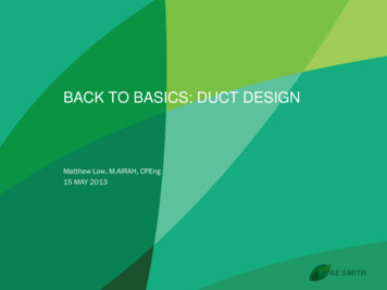
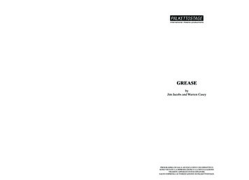
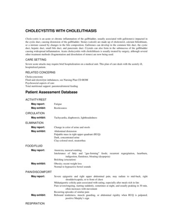
Joint AssemblyAccording to NFPA 96, all grease ducts are to be liquid tight. The following steps are tobe used to ensure this requirement is met.Model DWGD-RZDuct Size (Area)# of Joints per Tube6”x6” (36 in²)206”x12”(72 in²)136”x18”(108 in²)106”x24”(144 in²)86”X36”(216n²)612”x24” (288in²)512”x36” (432 in²)518”x36” (648 in²)424”x36”(864 in²)432”x34” (1088 in²)336”x36” (1296 in²)3Use high temperature silicone sealant, Jeremias part number 101087A. WARNING: Donot substitute any type of water soluble sealants in the flange area.To Install:1. Inspect all liner flanges, and draw bands and straighten any mild deformationsthat may have occurred during shipping.2. To ensure sealant adhesion, degrease and remove any dirt and debris from theliner flanges. Use an acetone based cleaner sprayed on a rag.3. Apply a continuous bead of sealant (1/8” to 1/4”) to one or both of the linerflanges to be joined.4. Butt the flanged ends of the sections being joined, being careful not to smear offthe sealant.a. Install all supplied bolts/nuts finger tight. After all bolt/nuts areTable 1-6. Sealant Usage Chartinstalled on a joint snug them up. After everything is snug finishtightening all bolts to an approx. torque of 4 ft-lb, per bolt manufactures recommended bolt torque.b. Remove / wipe smooth any excess sealant on the inside of the assembled duct.c. Allow sealant to cure 7 days before use. Sealant will not bond to flanges if moistureis introduced into system before sealant has cured.5. With the provided insulation strip, wrap the assembled joint (3) times completely with a 2”overlap at the end of the last wrap. Wrap the joint tight enough for the insulation to fit snug inthe space between the liner & shell. (This method applies wherever a joint requires to bewrapped prior to installing a draw band or cover.)6. Complete the grease duct enclosure by placing the draw band around and overlapping theshell flanges of the assembled components. With the provided fasteners and appropriate toolsdraw up the band accordingly. It is recommended that sealant (provided by others) be appliedto the draw band edges to prevent moisture from entering between the duct walls on allsections exposed to the atmosphere. As necessary, self taping screws can also be used tohelp seal the draw band to the outer shell. (provided by others). Recommended to have aminimum of two screws, per band, in the vertical run.FLANGE / DRAW BAND FASTENERSThe fasteners provided with the flange are standard ¼”-20 hex bolts and nuts. Draw band fasteners are¼” – 20 philips pan head screws with square nuts. Fittings come standard with draw band/cover, thefasteners provided for the flange will be plated steel. The provided fasteners for draw band/cover will beplated steel (where the shell is aluminized steel) or stainless steel (where the shell is stainless steel).Fig 1-6. Apply SealantINSULATION - STRIP WIDTHS & FIRE STOP PACKINGWhere the finished duct assembly uses a draw band (part DWGD-RZ**DRW*) a 4” wide roll of strip insulation is provided. Draw bands are typicallyused wherever standard fittings are assembled in series (mostfittings are provided with a draw band and roll of insulation strips).Where the duct penetrates through a wall or floor: a Fire StopPenetration is to be used, the insulation for packing the opening isprovided in 48” wide strips (the factory may provide 24” wide strips,or a package/container of insulation marked as “Fire Stop PackingMaterial” or “Fire Stop Insulation” as an alternate).Fig 1-7. Assemble Joint7Jeremias INSTALL RZ Rev:9/22/2021
SECTION 2 – SUPPORT & GUIDINGNOTES: The structural engineer for the project should select support member channels, beams,rods, wires/cables, etc. and joining methods in accordance with Good Engineering Practices to suiteeach specific application. Rods, wires/cables should only be used for hangers, NOT supports.Jeremias accepts no responsibility for the design and/or modification of buildings or structures toaccept the given load. All support framing, anchoring methods, etc. are by others.Duct WeightThe approximate installed weight of DWGD-RZ duct systems can be found using Table 2-1. Thistable does not include accessories such as supports and guides, fittings nor shipping packaging orpalletizing weight (See Table 2-1).Vertical Support Spacing and LimitsDWGD-RZ Duct vent must be supported properly. Several support options are available. Refer toTable 2-2 for maximum support height capabilities. For all support options, ensure non-combustiblehanger straps (or similar) are secured into joists or other solid structures. Ensure all minimumclearances to combustibles are maintained. Never drill or screw through the duct system. Additionalsupport must always be located at an elbow or offset to prevent unacceptable stress on that fitting.Model DWGD-RZDuct Size (Area)Lbs. per foot6”x6” (36 in²)186”x12”(72 in²)246”x18”(108 in²)296”x24”(144 in²)356”X36”(216n²)4112”x24” (288in²)4712”x36” (432 in²)5218”x36” (648 in²)5824”x36”(864 in²)6432”x34” (1088 in²)7136”x36” (1296 in²)75Table 2-1. Duct WeightTable 2-2 – Maximum Support HeightSize (Area)Max Load (LBS)Max Height (Ft.)Plate SupportAssembly (PLS)2,400 Lbs.Flange SupportAssembly (FSA)3,400 Lbs.Maximum Support HeightHorizontal Angle Support Horizontal Hangeror Unistrut SupportsBands (BHB)500 Lbs.420 Lbs.Wall Brackets (WBR)4” to 32”1,300 Lbs.Wall Brackets (WBR)34” to 48”900 Lbs.6”x6” (36 in²)133.3188.927.823.372.250.06”x12”(72 in²)100.0141.720.817.554.237.56”x18”(108 in²)82.8117.217.214.544.831.06”x24”(144 582.912.210.231.722.012”x24” (288in²)51.172.310.68.927.719.112”x36” (432 in²)46.265.49.68.125.017.318”x36” (648 in²)41.458.68.67.222.415.524”x36”(864 in²)37.553.17.86.620.314.132”x34” (1088 in²)33.847.97.05.918.312.736”x36” (1296 in²)32.045.36.75.617.312.08Jeremias INSTALL RZ Rev:9/22/2021
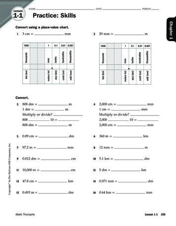
Lateral Guide SpacingDWGD-RZ systems require guides to maintain proper alignment of the system and lateralsupport for wind loads. Refer to Table 2-3 & Fig. 2-1 (Dim B) for Lateral Guide Spacing.Horizontal Support SpacingHorizontal installations require guides to maintain proper alignment of the system and lateralsupport for wind loads. Horizontal supports are used in conjunction with rods or other fieldfabricated support members attached to the building or structure. Position the support awayfrom draw bands & covers. Please note max. spacing of 12 foot making sure to stay within theweight limitation. Refer to Table 2-3 and Fig 2-2.Table 2-3 – Maximum Lateral / Horizontal Spacing Between SupportsSizeMaximum LateralMaximum HorizontalGuide SpacingSupport SpacingAll Sizes30’12’Full Angle Support – (FAS)Full angle supports, in conjunction with field fabricated support members from the FAS attachedto the building or structure, are intended to laterally brace the vertical assembled duct lengthsfrom wind loads and to also maintain alignment as the duct expands and contracts. The FAS iscomprised of (2) halves and when bolted together is a slight clearance fit to the duct. Positionthe FAS away from draw bands & covers as to allow for the unrestricted expansion andcontraction of the duct system. FAS’s cannot be installed over draw bands. See Fig 2-1 & 2-2.Fig 2-1. Lateral Guide SpacingGuy Attachment Plate – (GAP)Guy attachment plate, in conjunction with wires, tensioners, anchors, and othermiscellaneous hardware from the GAP attached to the building structure, areintended to laterally brace the vertical assembled duct lengths from wind loadsand to also maintain alignment as the duct expands and contracts. See Fig 2-3.To Install:1. Connect duct sections per the standard Joint Assembly instructions insection 1.2. Install the necessary wires, tensioners, anchors & miscellaneoushardware (by others) to the plate of the GAP. A minimum of (4)wires/cables equally spaced is recommended.Fig 2-2. Horizontal Support SpacingFig 2-3. Guy Attachment Plate (GAP)9Jeremias INSTALL RZ Rev:9/22/2021
Plate Support Assembly – (PLS)Plate support assemblies are used for vertical & horizontal (breeching anchor) structural support applications. The PLS is to be used with structuralsupport members, which are designed by the building structural engineer. Refer to table 2-1 & 2-2 for structural support limitations.To Install:1. Refer to Table 2-1 & 2-2 for load limitations.2. Position the plate support between the flanges. See Fig 2-5.3. Secure the joint per the standard Joint Assembly Instructions, sandwiching the plate support between the duct flanges.4. Fasten / secure Plate Support to Structural Members. Do not install to combustible material. Ensure all four sides of the plate aresupported. Design support member and fasteners in accordance with goodengineering practices to suit each specific application. Jeremias assumes noresponsibility for the design and/or modification of buildings or structures toaccept the given loads. See Fig 2-6 & 2-7.Fig 2-4. Plate Support Assembly (PLS)Fig 2-5. Plate Support Assembly (PLS)Fig 2-6. Plate Support Assembly (PLS)Fig 2-7. Plate Support Assembly (PLS)10Jeremias INSTALL RZ Rev:9/22/2021
Flange Support Assembly – (FSA)A Flange Support Assembly is a prefabricated duct section with a plate support installed at the factory for structural support applications. The FSA isto be used with structural support members, which are designed by the building structural engineer.To Install:1. Refer to Table 2-1 & 2-2 for load limitations.2. Fasten / secure Plate Support to Structural Members. Do not installto combustible material. Ensure all four sides of the plate aresupported. Design support member and fasteners in accordancewith good engineering practices to suit each specific application.Jeremias assumes no responsibility for the design and/ormodification of buildings or structures to accept the given loads.See Fig 2-8.3. Refer to Joint Assembly section to connect adjacent duct segmentsto the FSA.Fig 2-8. Flange Support Assembly (FSA)Wall Brackets – (WBR)Wall brackets are used in conjunction with our vertical and horizontalstructural and lateral supports. The WBR, in conjunction with anchor bolts orin some instances additional field fabricated support members from the wall brackets to the building or structure, is intended to provide a rigid (static)support location. This rigid support location is intended to withstand the weight of duct components, forces from thermal expansion & exhaustvelocities, etc. The WBR is comprised of (2) wall brackets, (left and right).To Install:1. Refer to Table 2-1 & 2-2 for load limitations.2. Anchor the wall brackets to the wall or additional field fabricated support members accordingly. Design support member and fasteners inaccordance with good engineering practices to suit each specific application. Consult structural engineer regarding design and/ormodification of buildings or structures to accept the given loads. Do not anchor to combustible material. See Fig 2-9 to 2-11.Fig 2-9. Wall Bracket (WBR)Fig 2-10. Wall Bracket (WBR)Fig 2-11. PLS installed on WBR11Jeremias INSTALL RZ Rev:9/22/2021
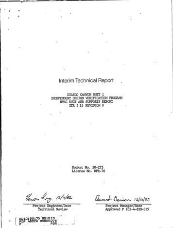
SECTION 3 – DUCT SECTIONS & FITTINGSDuct SectionsA wide range of prefabricated adapters, fittings, elbows, wye’s, tee’s, transitions, increasers, terminations, etcare available. Sections may also be equipped (must be factory installed) with nipples or couplings toaccommodate test probes, fire suppression nozzles, sprinkler heads, drainage, etc. Refer to the DWGD-RZcatalog for additional information on part number designations and the wide range of parts and fittings weoffer to complete a system from start to finish. Additionally, where required, custom lengths may be orderedfrom Jeremias Inc.Straight Sections (STR)Model DWGD-RZ is available in a variety of fixed duct lengths (e.g., 18”, 30” & 42”). Refer to the catalog foravailable sizes. Additionally, where required, custom lengths may be ordered from Jeremias Inc. Refer to thecorresponding Joint Assembly section for installation instructions. See Fig 3-1.Elbow (E)Elbows are used to provide changes in direction. They are available in a variety of standard angles (1.5 , 3 ,15 , 30 , 45 , 70 , 87 , & 90 ). Refer to the catalog for available sizes. Additionally, where available,custom elbows may be ordered from Jeremias Inc. Elbows are installed similar to standard duct. Refer tothe corresponding Joint Assembly section for installation instructions. See Fig 3-2.Fig 3-1. Straight SectionTee (90T)Used as a manifold entry Tee, offset with one of the access cap options, or cleanoutoption. Branch can be same or any size smaller than the body. See Fig 3-3.Wye Tee (WYE)Used for two-way entries where a tee cap or access cannot be used due to the applicationor as a 90 that can have an access cap at the middle.Fig 3-2. ElbowFig 3-3. 90TFig 3-4. WYEFig 3-5. Test Port Section12Jeremias INSTALL RZ Rev:9/22/2021
Fan/Hood Adapter Assembly – (FAA)The fan adapter assembly is intended to be used with a “traditional” roof curb (provided by others)and connection to a hood or an exhaust fan. The FAA is comprised of a fan adapter plate (specifyplate size at time of purchase) with a factory installed starter section that assembles to a standardfitting. Field connect the plate to the hood, curb or fan by (drilling / fasteners & sealant by others asrequired). Refer to the hood, fan unit or the roof curb manufacturer’s installation requirements. (SeeFig 3-6).ACCESS PANEL SECTION – (APS)This part is intended to be used for clean out access. When the access panel section is installed ina horizontal position, it must be orientated in accordance with applicable codes. Please refer to theDWGD-RZ catalog for additional information and part number designation. See Fig 3-7.Fig 3-6. Fan Adapter Assembly(FAA)Open Top Closure – (OTC)The open top closure covers the space between the liner and shell. First, position the OTC aroundthe liner. Next, butt the OTC up against the flange of the liner and using the provided fastenersdraw up the OTC. Last, apply a bead of sealant at the seam formed between OTC and the liner toform a weather tight seal. See Fig 3-8.Rain Cap – (RCS)Rain caps connect to the liner flange per the joint assembly instructions. The space between theliner and shell is then covered using a rain skirt. The rain skirt is installed by positioning the rainskirt around the liner just below the previously installed flange. Next, using the provided fastenersdraw up the rain skirt (the rain skirt should be overlapping and in contact with the top of the shell).Last, apply a bead of sealant at the seam formed between rain skirt and the liner to form a weathertight seal. See Fig 3-9.Increasers and ReducersReduction fittings are typically used in manifold applications when needed. There are many optionsfor increasers and reducers.Fig 3-7. Access Panel Section(APS)Single-to-Double-Wall / Double-to-Single-Wall Adapters (D2S & S2D)These adapters allow a smooth transition to and from double wall and single wall. They may be installed vertically or horizontally. Adapters aremade to order for project requirements.Transition to Round Start & End (TRS & TRE)Used to connect to and from rectangular or square outlets on hood, fans, or auxiliary equipment. Transitions are custom made to order for projectrequirements. The rectangular or square base can be made in accordance with NFPA-96 no-weld hood connection or may be field welded by theinstalling contractor.Fig 3-8. Open Top Closure (OTC)Fig 3-9. Rain Cap (RCS)13Jeremias INSTALL RZ Rev:9/22/2021 p
fire suppression equipment. Refer to NFPA 96 and additional codes / authorities having jurisdiction for specific duct system requirements. Wash Down & Fire Suppression Automatic hot water / detergent wash down and fire suppression systems can be integrated into a Model DWGD-RZ grease duct system by using