Transcription
UFC 4-214-0317 March 2018UNIFIED FACILITIES CRITERIA (UFC)CENTRAL VEHICLE WASHFACILITIESAPPROVED FOR PUBLIC RELEASE; DISTRIBUTION UNLIMITEDUNIFIED FACILITIES CRITERIA (UFC)
UFC 4-214-0317 March 2018CENTRAL VEHICLE WASH FACILITIESAny copyrighted material included in this UFC is identified at its point of use.Use of the copyrighted material apart from this UFC must have the permission of thecopyright holder.U.S. ARMY CORPS OF ENGINEERS (Preparing Activity)NAVAL FACILITIES ENGINEERING COMMANDAIR FORCE CIVIL ENGINEER CENTERRecord of Changes (changes are indicated by \1\ . /1/)Change No.DateLocationThis UFC supersedes UFC 4-214-03, dated JAN 2004 and TM 5-814-9, dated FEB1992.
UFC 4-214-0317 March 2018FOREWORDThe Unified Facilities Criteria (UFC) system is prescribed by MIL-STD 3007 and providesplanning, design, construction, sustainment, restoration, and modernization criteria, and appliesto the Military Departments, the Defense Agencies, and the DoD Field Activities in accordancewith USD (AT&L) Memorandum dated 29 May 2002. UFC will be used for all DoD projects andwork for other customers where appropriate. All construction outside of the United States isalso governed by Status of Forces Agreements (SOFA), Host Nation Funded ConstructionAgreements (HNFA), and in some instances, Bilateral Infrastructure Agreements (BIA.)Therefore, the acquisition team must ensure compliance with the most stringent of the UFC, theSOFA, the HNFA, and the BIA, as applicable.UFC are living documents and will be periodically reviewed, updated, and made available tousers as part of the Services’ responsibility for providing technical criteria for militaryconstruction. Headquarters, U.S. Army Corps of Engineers (HQUSACE), Naval FacilitiesEngineering Command (NAVFAC), and Air Force \2\ Civil Engineer Center (AFCEC) /2/ areresponsible for administration of the UFC system. Defense agencies should contact thepreparing service for document interpretation and improvements. Technical content of UFC isthe responsibility of the cognizant DoD working group. Recommended changes with supportingrationale should be sent to the respective service proponent office by the following electronicform: Criteria Change Request. The form is also accessible from the Internet sites listed below.UFC are effective upon issuance and are distributed only in electronic media from the followingsource: Whole Building Design Guide web site http://dod.wbdg.org/.Hard copies of UFC printed from electronic media should be checked against the currentelectronic version prior to use to ensure that they are current.AUTHORIZED BY:DR. LARRY McCALLISTER, P.E.JOSEPH E. GOTT, P.E.Chief, Engineering and ConstructionU.S. Army Corps of EngineersChief EngineerNaval Facilities Engineering CommandEDWIN H. OSHIBA, SES, DAFMICHAEL McANDREWDeputy Director of Civil EngineersDASD (Facilities Investment and Management)Office of the Assistant Secretary of Defense(Energy, Installations, and Environment)DCS/Logistics, Engineering &Force Protection
UFC 4-214-0317 March 2018UNIFIED FACILITIES CRITERIA (UFC)REVISION SUMMARY SHEETDocument: UFC 4-214-03, Central Vehicle Wash FacilitySuperseding: TM 5-814-9Description: This criteria is a comprehensive reference for scoping, design, andconstruction of vehicle wash facilities and their appurtenant structures.Reasons for Document: Criteria formatting was updated to conform to UFC 1-300-01. Criteria was updated to include sustainable design features, namely Net-Zerowater usage considerations for scoping, design, and construction. Criteria was updated to reflect current codes and methodology.Impact: The update to this criteria will provide a path to more sustainable designs bymeans of water use reduction.
UFC 4-214-0317 March 2018TABLE OF CONTENTSCHAPTER 1 INTRODUCTION . 11-1PURPOSE AND SCOPE. . 11-2APPLICABILITY. . 11-3GENERAL BUILDING REQUIREMENTS. . 11-4BACKGROUND. . 11-5REFERENCES. . 21-6GLOSSARY. . 2CHAPTER 2 CVWF DESIGN CONCEPT . 32-1OVERVIEW. . 32-2PREWASH (OPTIONAL). . 32-3WASTEWATER TREATMENT. . 32-3.1Primary Treatment. . 32-3.2Secondary Treatment. . 32-3.3Water Supply Basin. . 6CHAPTER 3 MASTER PLANNING . 73-1SIZING. . 73-1.1User Input. . 73-1.2Prewash. . 123-1.3Wash Stations. 153-2SITING. . 163-2.1Geography. . 163-2.2Weather. . 183-2.3Geology. . 193-2.4Utilities. . 21CHAPTER 4 DESIGN . 254-1VEHICLE PREPARATION AREA. . 254-1.1General. . 254-1.2Sizing. . 254-1.3Staging Area Cleanup. . 254-1.4Drainage. . 264-24-2.1WASH STATION. . 26Function. . 26i
UFC 4-214-0317 March 20184-2.2Configuration. . 264-2.3Island Design. . 284-2.4Tower Design. 284-2.5Protection Against Freezing. . 314-2.6Water Supply Piping. . 314-2.7Paved Area Drainage. . 314-2.8Pavement. 344-2.9Interior Wash Equipment (Optional). . 354-2.10Lighting. . 354-2.11Physical Security. . 354-2.12Signage. 354-2.13Solid Waste Collection. . 354-2.14Operation and Controls. . 35CHAPTER 5 OPTIONAL PREWASH . 395-1TYPES OF PREWASHES. . 395-1.1Bath Prewash. . 395-1.2Vehicle Spray Stands. . 475-1.3Bath Prewash Support Facilities. . 51CHAPTER 6 WASTEWATER TREATMENT . 536-1GENERAL CONCEPTS. . 536-1.1Overview. . 536-1.2Treatment System. . 536-2DESIGN PARAMETERS. . 546-2.1Criteria. . 546-2.2Wash Period (Tw). . 546-2.3Cleanup Time (K). . 546-2.4Water Usage Factor (Uf). . 546-2.5Storm Water. 556-2.6Stormwater Bypass. . 556-2.7Washwater Demand. . 556-2.8Water Volume. . 566-36-3.1PRIMARY TREATMENT. . 58Function. . 58ii
UFC 4-214-0317 March 20186-3.2Number of Basins. . 586-3.3Siting. . 596-3.4Sizing. . 606-3.5Sediment Basin Influent Structure. . 636-3.6Sediment Basin Effluent Structure. . 636-3.7Sediment Basin Construction. 636-3.8Sediment Basin Drainage. . 646-3.9Sediment Removal. . 676-3.10Oil Removal. . 676-3.11Waste Oil Storage. . 676-3.12Maintenance. . 676-3.13Other Considerations. . 676-4SECONDARY TREATEMENT. . 686-4.1Onsite Secondary Treatment. . 686-4.2Objective. . 686-4.3Intermittent Sand Filter System. 696-4.4Lagoon System. . 816-4.5Discharge System. . 826-5WATER SUPPLY BASIN. . 846-5.1Introduction. . 846-5.2Capacity. . 846-5.3Liner. . 856-5.4Influent Structure. . 856-5.5Service. . 856-5.6Security. . 85CHAPTER 7 OTHER DESIGN CONSIDERATIONS . 877-1WATER SOURCE. . 877-1.1Type of Facility. . 877-1.2Type and Configuration of Treatment System. . 877-1.3Climate. 877-2PIPING. 887-3HOSES, WATER CANNONS, AND NOZZLES. . 887-4CONTROL SYSTEMS. . 88iii
UFC 4-214-0317 March 20187-5SYSTEMS OPERATING MANUAL. . 88CHAPTER 8 DECENTRALIZED WASH FACILITES . 918-1OVERVIEW. . 918-2PLANNING. . 918-2.1Planning Considerations. . 918-2.2Requirements. . 928-3DESIGN CONCEPT FOR DECENTRALIZED VEHICLE WASHSTATIONS. . 928-3.1Overview. . 928-3.2Conceptual Design. . 928-4DESIGN & CONSTRUCTION: “DECENTRALIZED” NET ZERO WASHFACILITY. . 948-4.1Design Features. . 948-4.2Construction Details. . 998-5OPERATION AND MAINTENANCE. . 1008-5.1Operation and Organization Maintenance Tasks. . 1018-5.2Maintenance. . 1018-6PERFORMANCE. . 1018-6.1Past Performance. . 1018-6.2Water Quality. . 101APPENDIX A REFERENCES . 103APPENDIX B BEST PRACTICES . 105B-1CASE STUDY: DECENTRALIZED VEHICLE WASH FACILITY. . 105B-1.1Background. 105B-1.2Construction. 105B-1.3Performance. . 108B-1.4Conclusion. . 109B-2DESIGN EXAMPLE . 109B-2.1Introduction. . 109B-2.2Master Planning Considerations. . 110B-2.3Engineering and Design. 117APPENDIX C GLOSSARY . 143C-1ACRONYMS . 143C-2DEFINITION OF TERMS . 144iv
UFC 4-214-0317 March 2018APPENDIX D “DECENTRALIZED HEAVY SOLIDS WASH RACK SITE SURVEY . 149FIGURESFigure 1-1 Standard Sequence for Tactical Vehicles . 2Figure 1-2 Washing Procedure with Optional Prewash . 2Figure 2-1 Standard Central Vehicle Wash Facility Plan . 5Figure 2-2 Central Vehicle Wash Facility Plan with Bath Prewash . 6Figure 3-1 Cohesive Soil Gradation Curve . 9Figure 3-2 Noncohesive Soil Gradation Curve . 10Figure 3-3 Soil Classification and Soil Type Number Diagram . 11Figure 3-4 Vehicle Processing Rates (Vehicles per Hour) . 13Figure 4-1 Skewed Wash Station Arrangement . 27Figure 4-2 Wash Island Plan Showing Spacing . 28Figure 4-3 Double-Tower Island . 29Figure 4-4 Cross Section of an Island . 30Figure 4-5 Longitudinal Section of an Island . 32Figure 4-6 Tower Detail in Cross Section . 33Figure 4-7 Cross Section of a Trench Drain . 34Figure 4-8 Example Floor Plan for the Control Building . 37Figure 4-9 Control Building Exterior . 38Figure 5-1 Example of Combined Bath Lane Facility, Plan view . 40Figure 5-2 Tracked Bath Lane, Cross Section . 41Figure 5-3 Example Inner Wash Island . 42Figure 5-4 Example of Outer Wash Island . 43Figure 5-5 Example Cross Section of a Cannon Island . 44Figure 5-6 Tracked Bath Lane. 45Figure 5-7 Dual Purpose Lane . 48Figure 5-8 U-Drain. 49Figure 5-9 Bath Cross Section . 49Figure 5- 10 Configuration of U-Drains in the Bath . 50Figure 5-11 Water Level Control Structure . 51Figure 6-1 Single Cell Sediment Basin, Plan View . 59Figure 6-2 Single Cell Sediment Basin, Cross Section. 60Figure 6-3 Dual Cell Sediment Basin, Plan View . 60Figure 6-4 Dual Cell Sediment Basin, Cross Section . 61Figure 6-5 Typical Design Water and Sediment Depths. 61Figure 6-6 Typical Effluent Structure with an Overflow Trench, Sedimentation Basinswithout Bath . 65Figure 6-7 Typical Effluent Structure with Motorized Gates, Sediment Basins with Bath. 65Figure 6-8 Sedimentation Basin Drain System. 66Figure 6-9 Components of an Intermittent Sand Filter System. 68Figure 6-10 General Schematic of an Intermittent Sand Filter Recycle System . 69Figure 6-11 Example Equalization Basin, Plan View . 70Figure 6-12 Equalization Basin, Cross Section . 71Figure 6-13 Distribution System Using Grid Arrangement. 76v
UFC 4-214-0317 March 2018Figure 6-14 Distribution Box . 77Figure 6-15 Distribution System Using Distribution Boxes . 78Figure 6-16 Collection System . 80Figure 6-17 Intermittent Sand Filter Cross Section . 81Figure 6-18 Components of a Lagoon System . 82Figure 6-19 General Flow Schematic of a Lagoon System . 83Figure 6-20 Components of a Total Discharge System . 84Figure 6-21 General Flow Schematic of a Total Discharge System . 85Figure 6-22 Water Supply Basin, Plan View. 86Figure 6-23 Water Supply Basin, Cross Section . 86Figure 8-1 Decentralized Wash Facility Layout . 97Figure 8-2 Single Lane, Heavy Solids Wash Rack . 97Figure 8-3 Dual Lane, Net Zero, Heavy Solids Wash Rack. 98Figure 8-4 Quad Lane, Net Zero, Heavy Solids Wash Rack . 98Figure 8-5 Dual Lane, Net Zero Wash Lane with Heavy Solids and Detailing Lanes . 99Figure B-1 Decentralized Dual Lane Wash Facility . 105Figure B-2 Vehicles Returning from the Training Areas each Month . 112Figure B-3 Site Map with a Proposed Layout – Fort Swampy . 118Figure B-4 Bath Design . 119Figure B-5 Configuration A . 122Figure B-6 Configuration B . 123Figure B-7 Cross Section of the Bath . 124Figure B-8 Water Volume Configuration: (a) Plan View and (b) Cross Section . 134Figure B-9 Overall Cell Configuration . 136Figure B-10 Equalization Basin: (a) Plan View and (b) Cross Section . 137Figure B-11 Water Supply Basin: (a) Plan View and (b) Cross Section . 139Figure B-12 Equalization Basin Water Balance – Water Volume versus Time. 141Figure B-13 Water Supply Basin Capacity . 142TABLESTable 6-1 Estimated Volume of Material per Vehicle. 62Table B-1 Number of Vehicle Types by Motor Pool Assignment . 111Table B-2 Number of Vehicles Returning from the Field each Month . 112Table B-3 Summary of CVWF Flow Rates . 128Table B-4 Summary of Average Daily Volume . 130Table B-5 Summary of Maximum Volumes . 132vi
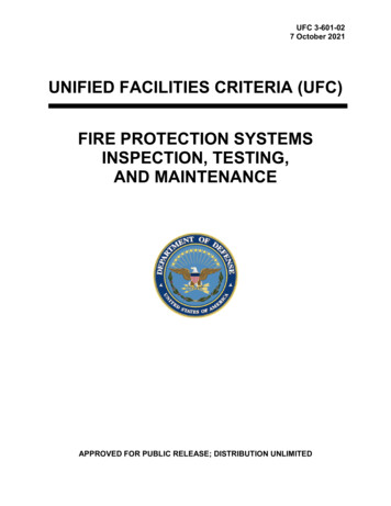
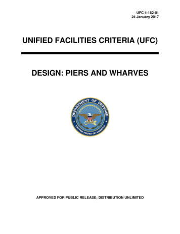
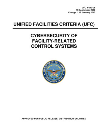
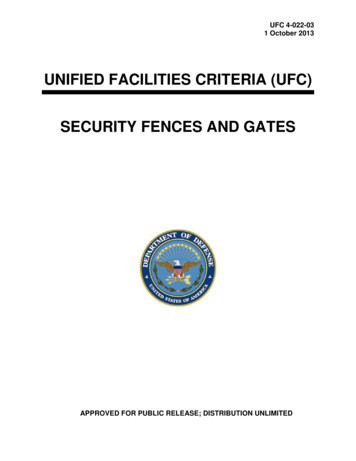
UFC 4-214-0317 March 2018CHAPTER 1 INTRODUCTION1-1PURPOSE AND SCOPE.This manual provides a comprehensive reference source for planning, and designing acentral vehicle wash facility (CVWF) and decentralized, net zero wash facilities. TheCVWF provides a rapid, economical method for washing tracked and wheeled tacticalvehicles. The design elements provide for water pollution control, solid waste disposal,and conservation of manpower and water. This manual is limited to wash facilities andwastewater treatment for cleaning vehicle exteriors only; this design information doesnot pertain to facilities for treating wastewater from maintenance cleaning activities.The Original Technical Manual (TM) 5-814-9 was adopted in 1992 to provide for largeoperational and rapid washing of tracked and wheeled tactical vehicles. The TechnicalManual was converted to the current UFC 4-214-03 in 2004 utilizing the same conceptsfor washing tactical vehicles. The detailed requirements for washing these typevehicles are based on large lay-down areas and large quantities of water withintroduction of new water as necessary. This update incorporates Chapter 8 whichintroduces new Net Zero design capabilities for Installations to meet the current needsfor saving water and utilizing smaller lay-down areas for washing tactical vehicles.Installations are encouraged to review this alternative method of washing tacticalvehicles in combination with the modernization of the type of wheeled vehiclesnecessary for rapid deployments. The Net Zero Concept is especially pertinent forchanging climate and for smaller installations with large Reserve Components.1-2APPLICABILITY.Information in this manual applies central vehicle wash facilities and decentralized, netzero wash facilities on all installations that maintain a fleet of tactical vehicles for whichthere is a consistent washing requirement demanding cost-effective, on- post facilities.1-3GENERAL BUILDING REQUIREMENTS.Comply with UFC 1-200-01, General Building Requirements. UFC 1-200-01 providesapplicability of model building codes and government unique criteria for typical designdisciplines and building systems, as well as for accessibility, antiterrorism, security, highperformance and sustainability requirements, and safety. Use this UFC in addition toUFC 1-200-01 and the UFCs and government criteria referenced therein. All applicablecodes and criteria should be followed, including, but not limited to the InternationalBuilding Code (IBC) and UFC 3-600-01 Fire Protection.1-4BACKGROUND.The Department of Defense has unique vehicle cleaning requirements in terms ofnumbers, types of vehicles, washing time, and degree to which washing is critical.Civilian technologies for cleaning off-road tactical vehicles and treating the wastewatercreated by this washing are not recommended. However, civilian technology may applyto facilities for washing vehicles in a transportation motor pool (TMP), most of which arethe wheeled, on-road type such as sedans and buses. Figure 1-1 shows the1
UFC 4-214-0317 March 2018recommended washing sequence for tactical vehicles. For installations where specificconditions require that a prewash be constructed, the washing procedure is shown inFigure 1-2. The central vehicle wash facility is designed to provide expedient, costeffective vehicle cleaning for tactical vehicles. The concept incorporates waterconservation including recycle techniques and pollution control.Figure 1-2 Washing Procedure withOptional PrewashFigure 1-1 StandardSequence for TacticalVehicles1-5REFERENCES.Appendix A contains a list of references used in this document. The publication date ofthe code or standard is not included in this document. In general, the latest availableissuance of the reference is used.1-6GLOSSARY.Appendix C contains acronyms, abbreviations, and terms.2
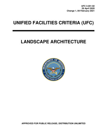
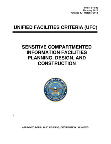
UFC 4-214-0317 March 2018CHAPTER 2 CVWF DESIGN CONCEPT2-1OVERVIEW.The standard CVWF consists of a vehicle preparation area, wash stations, and vehicleassembly area Figure 2-1 Standard Central Vehicle Wash
CENTRAL VEHICLE WASH FACILITIES . UFC 4-214-03 17 March 2018 . CENTRAL VEHICLE WASH FACILITIES . Any copyrighted material included in this UFC is identified at its point of use. Use of the copyrighted material apart from this UFC must have the permission of the copyright holder.