Transcription
UFC 3-501-01October 6, 2015Change 1, 01 November 2019UNIFIED FACILITIES CRITERIA (UFC)ELECTRICAL ENGINEERINGAPPROVED FOR PUBLIC RELEASE; DISTRIBUTION UNLIMITED
UFC 3-501-01October 6, 2015Change 1, 01 November 2019UNIFIED FACILITIES CRITERIA (UFC)ELECTRICAL ENGINEERINGAny copyrighted material included in this UFC is identified at its point of use.Use of the copyrighted material apart from this UFC must have the permission of thecopyright holder.U.S. ARMY CORPS OF ENGINEERSNAVAL FACILITIES ENGINEERING COMMAND (Preparing Activity)AIR FORCE CIVIL ENGINEER CENTERRecord of Changes (changes are indicated by \1\ . /1/)Change No.1Date01 November2019LocationAdded Environmental Severity Classification andhumidity design requirements and updated corrosionprevention requirements in 1-3.1, 2-1.11 and AppendixF.This UFC supersedes UFC 3-501-01, dated 3 February 2010, with Changes 1-3.
UFC 3-501-01October 6, 2015Change 1, 01 November 2019FOREWORDThe Unified Facilities Criteria (UFC) system is prescribed by MIL-STD 3007 and providesplanning, design, construction, sustainment, restoration, and modernization criteria, and appliesto the Military Departments, the Defense Agencies, and the DoD Field Activities in accordancewith USD (AT&L) Memorandum dated 29 May 2002. UFC will be used for all DoD projects andwork for other customers where appropriate. All construction outside of the United States isalso governed by Status of Forces Agreements (SOFA), Host Nation Funded ConstructionAgreements (HNFA), and in some instances, Bilateral Infrastructure Agreements (BIA.)Therefore, the acquisition team must ensure compliance with the most stringent of the UFC, theSOFA, the HNFA, and the BIA, as applicable.UFC are living documents and will be periodically reviewed, updated, and made available tousers as part of the Services’ responsibility for providing technical criteria for militaryconstruction. Headquarters, U.S. Army Corps of Engineers (HQUSACE), Naval FacilitiesEngineering Command (NAVFAC), and Air Force Civil Engineer Center (AFCEC) areresponsible for administration of the UFC system. Defense agencies should contact thepreparing service for document interpretation and improvements. Technical content of UFC isthe responsibility of the cognizant DoD working group. Recommended changes with supportingrationale should be sent to the respective service proponent office by the following electronicform: Criteria Change Request. The form is also accessible from the Internet sites listed below.UFC are effective upon issuance and are distributed only in electronic media from the followingsource: Whole Building Design Guide web site http://dod.wbdg.org/.Refer to UFC 1-200-01, General Building Requirements, for implementation of new issuanceson projects.AUTHORIZED BY:JAMES C. DALTON, P.E.JOSEPH E. GOTT, P.E.Chief, Engineering and ConstructionU.S. Army Corps of EngineersChief EngineerNaval Facilities Engineering CommandRANDY E. BROWN, SESMICHAEL McANDREWDirectorAir Force Civil Engineer Center(DASD)Facilities Investment and ManagementOffice of the Assistant Secretary of Defense(Energy, Installations, and Environment)
UFC 3-501-01October 6, 2015Change 1, 01 November 2019UNIFIED FACILITIES CRITERIA (UFC)NEW DOCUMENT SUMMARY SHEETDocument: UFC 3-501-01, Electrical EngineeringSuperseding: UFC 3-501-01, Electrical Engineering, with Change 3, 1 July 2012.Description: This UFC 3-501-01 provides electrical engineering design and analysiscriteria for design-build and design-bid-build projects. It is organized to provide the toplevel minimum mandatory electrical requirements and refers to other UFCs asappropriate.Reasons for Document: Provides technical requirements for electrical system design criteria. Establishes design analysis requirements in support of design activities. Defines minimum requirements for design drawings in terms of drawing typesand content. Provides links to related material in other UFCs.Impact: There are negligible cost impacts associated with this UFC. However, thefollowing benefits should be realized. Standardized guidance has been prepared to assist electrical engineers in thedevelopment of the plans, specifications, calculations, and Design/BuildRequest for Proposals (RFP). This UFC coordinates with all electrical-related UFCs and providesrequirements consistent with the other electrical-related UFCsUnification Issues Section 2-1.3: The Army and Navy allow hot capping of conductors duringconstruction to maintain an energized circuit. Section 2-2.5: For cathodic protection systems, comply with UFC 3-570-02Nfor the Navy and UFC 3-570-02A for the Army. The unified UFC is underdevelopment and is at the 90% review level. Section 3-3: For the Navy, additionally comply with FC 1-300-09N for specificdrawing requirements and drawing phases.
UFC 3-501-01October 6, 2015Change 1, 01 November 2019TABLE OF CONTENTSCHAPTER 1 INTRODUCTION . 11-1PURPOSE AND SCOPE. . 11-1.1UFC Hierarchy . 11-1.2Upgrades and Modifications to Existing Systems . 11-2APPLICABILITY. . 11-3GENERAL BUILDING REQUIREMENTS. . 21-3.1Environmental Severity and Humid Locations . 21-4WAIVER AND EXEMPTION PROCESS. . 41-5REFERENCES. . 41-6DESIGN STANDARDS. 41-7CYBERSECURITY. . 51-8PERMITS – CONSTRUCTION, ENVIRONMENTAL, AND OTHER. . 5CHAPTER 2 DESIGN REQUIREMENTS . 72-1GENERAL. . 72-1.1Hazardous Materials and Waste, and Controlled Materials. . 72-1.2Removal of Existing Cables and Conductors. . 82-1.3Hot Caps and Removal of T-Splices Inside Manholes. . 82-1.4Modification to Existing Electrical Equipment. 82-1.5Salvaged Materials and Equipment. . 82-1.6Scheduling and Sequencing Outages. . 92-1.7Calculations. . 92-1.8Energy Efficiency and Sustainable Design. . 92-1.9Antiterrorism and Physical Security. . 92-1.10Facility Systems Safety. . 102-1.11Corrosive and High Humidity Areas. . 102-1.12Arc Flash Warning Labels. . 112-1.13NFPA 70 (NEC) / IEEE C2 (NESC) Design Interface Points. . 112-1.14Utility Interactive Systems (Microgrids). . 142-2SITE EXTERIOR POWER DISTRIBUTION SYSTEMS. 142-2.1Exterior Power Distribution Systems, Including Housing. . 142-2.2Dockside Utilities for Ship Service. . 14i
UFC 3-501-01October 6, 2015Change 1, 01 November 20192-2.3Exterior Lighting Systems. . 142-2.4Airfield Lighting. . 142-2.5Cathodic Protection Systems. . 142-2.6High-Altitude Electromagnetic Pulse (HEMP) Shielded Systems –Exterior. . 152-2.7Generators. . 152-3INTERIOR DISTRIBUTION SYSTEMS. . 152-3.1Interior Electrical Systems. . 152-3.2Interior Lighting Systems. . 152-3.3Emergency and Standby Systems. . 152-3.4Sensitive Compartmented Information Facilities (SCIF). . 152-3.5Hazardous Locations. . 152-3.6Battery Areas and Battery Racks. . 152-3.7HEMP Shielded Systems – Interior. . 162-4COMMUNICATIONS AND SECURITY. . 162-4.1Telecommunication Systems. . 162-4.2Television Systems. . 162-4.3Community Antenna Television (CATV) Systems. 162-4.4Electronic Security Systems (ESS). . 172-4.5Mass Notification Systems. . 17CHAPTER 3 DESIGN ANALYSIS AND DOCUMENTATION . 183-1GENERAL. . 183-2DESIGN ANALYSIS. . 183-2.1Basis of Design. . 183-2.2Electrical Calculations – Overview. . 213-2.3Load Analysis. . 233-2.4Short Circuit Analysis. . 263-2.5Protective Device Time-Current Coordination Study. . 273-2.6Arc Flash Analysis. . 293-2.7Voltage Drop. . 313-2.8Motor Starting/Flicker Analysis. . 313-2.9Lighting. . 313-2.10Underground Structures Design. . 31ii
UFC 3-501-01October 6, 2015Change 1, 01 November 20193-2.11Cable Pulling Tension Calculations. . 313-2.12Calculations for Directional Boring. . 323-2.13Sag, Tension, and Guying Analysis. . 323-2.14Cathodic Protection Calculations. . 323-2.15Lightning Protection Calculations. 323-2.16CATV Network Loss Calculations. . 323-2.17ESS Calculations. . 323-2.18Renewable Energy System Calculations. . 323-3DRAWING REQUIREMENTS. . 333-3.1Legends and Abbreviations. . 343-3.2Site Plans. 343-3.3Demolition Plans. . 363-3.4Lighting Plans and Details. . 373-3.5Power Plans. 383-3.6Communication Plans. . 383-3.7Grounding Plan. . 383-3.8Roof Plan. . 383-3.9Lightning Protection Plan. . 383-3.10Hazardous Location Plan. . 383-3.11Power One-Line/Riser Diagrams. . 393-3.12Telecommunications Riser Diagram. . 413-3.13Intercommunication/Paging Riser Diagram. 413-3.14Fire Alarm Riser Diagram. . 413-3.15Special Systems Riser Diagrams. . 413-3.16Schedules and Elevations. 413-3.17Details/Diagrams. . 433-3.18Grounding Diagrams. . 433-3.19Cathodic Protection Plans and Details. . 43APPENDIX A REFERENCES . 44APPENDIX B ELECTRICAL UFCS . 48APPENDIX C TRI-SERVICE ELECTRICAL WORKING GROUP TECHNICALPAPERS . 52APPENDIX D DESIGN DATA TABLES . 54iii
UFC 3-501-01October 6, 2015Change 1, 01 November 2019APPENDIX E ELECTRICAL ENGINEERING PRELIMINARY CONSIDERATIONS . 58APPENDIX F GLOSSARY . 80F-1ACRONYMS . 80F-2DEFINITION OF TERMS . 84FIGURESFigure 1-1 Electrical UFC Delineation . 3Figure 2-1 Illustration of NFPA 70 Service Point and NFPA 70 / IEEE C2Demarcation . 13Figure B-1 Additional Electrical-Related UFCs . 49Figure B-2 Additional Electrical-Related UFCs. 50TABLESTable D-1 Typical Loading For Personal Computer Systems. 54Table D-2 Load Data For Preliminary Demand Calculations . 54Table D-3 Dwelling Demand kVA per A/C Size . 55Table D-4 Typical A/C Size for Dwelling Units . 55Table D-5 Demand for Electric Strip Heat . 55iv
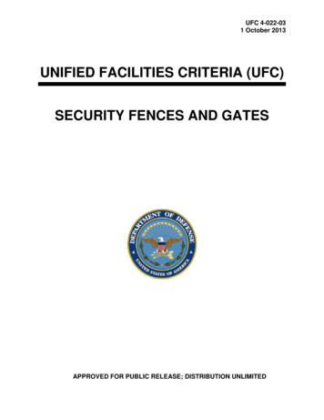
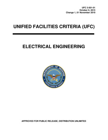
UFC 3-501-01October 6, 2015Change 1, 01 November 2019CHAPTER 1 INTRODUCTION1-1PURPOSE AND SCOPE.The purpose of this UFC is to provide technical requirements for general aspects of theelectrical design of projects. Apply the criteria provided in this UFC for the developmentof the plans, specifications, calculations, and Design/Build Request for Proposals(RFP). It serves as the minimum electrical design requirements for design-build anddesign-bid-build projects. Project conditions may dictate the need for a design thatexceeds these minimum requirements.1-1.1UFC HierarchyThis UFC provides the top-tier baseline requirements for electrical UFCs and isintended as a reference for all electrical work on projects. Figure 1-1 shows therelationship of this UFC to other related UFCs. They rely on this UFC for overallrequirements regarding design analysis and documentation. There are existingindividual service UFCs and other UFCs under development; these documents areidentified in similar figures in Appendix B.1-1.2Upgrades and Modifications to Existing SystemsModernization of electrical systems solely for the purpose of meeting design criteria inUFCs is not required. Upgrades or modifications to electrical systems should considerthe design criteria in this UFC, but it is not intended that an entire facility or systemrequire modernization solely because of a minor modification.For minor projects, determine if the project will affect existing electrical systemcalculations such as by modifying circuit breaker settings. If any electrical systemcalculations are affected by the modification, update the calculations, including the arcflash calculation, as part of the project.Note: Arc flash calculation updates are necessary for electrical safety.1-2APPLICABILITY.Compliance with this UFC is mandatory for the design of electrical systems at allfacilities and bases.Facilities located outside of the United States must also comply with the applicable hostnation standards; refer to UFC 3-510-01 for additional information. Different voltages,frequencies, and grounding conventions often apply in other host nations; however,follow the design principles provided in this UFC to the extent practical, as well as therequirements provided in UFC 1-202-01, Host Nation Facilities in Support of MilitaryOperations. U.S. Department of Commerce International Trade Administrationdocument, Electric Current Abroad, provides additional information and can be obtainedat ent2002final.pdf.1
UFC 3-501-01October 6, 2015Change 1, 01 November 20191-3GENERAL BUILDING REQUIREMENTS.UFC 1-200-01, DoD Building Code (General Building Requirements), providesapplicability of model building codes and government-unique criteria for typical designdisciplines and building systems, as well as for accessibility, antiterrorism, security,sustainability, and safety. Use this UFC in addition to UFC 1-200-01 and the UFCs andgovernment criteria referenced therein.1-3.1\1\ Environmental Severity and Humid Locations.In corrosive and humid environments, provide design detailing, and use materials,systems, components, and coatings that are durable and minimize the need forpreventative and corrective maintenance over the expected service life of thecomponent or system. UFC 1-200-01, section titled “Corrosion Prone Locations”identifies corrosive environments and humid locations requiring special attention. UFC1-200-01, section titled “Requirements for Corrosion Prone Locations” providesexamples of necessary actions. To determine Environmental Severity Classifications(ESC) for specific project locations refer to UFC 1-200-01 Appendix titled“Environmental Severity Classifications (ESC) for DoD Locations”. /1/2
UFC 3-501-01October 6, 2015Change 1, 01 November 2019Figure 1-1 Electrical UFC DelineationUFC 1-200-02High Performance andSustainable BuildingRequirementsUFC 1-200-01General BuildingRequirementsUFC 3-501-01Electrical EngineeringElectricalSafetyUFC 3-560-01Electrical Safety, O&MExteriorElectricalInteriorElectricalUFC 3-550-01Exterior ElectricalPower DistributionUFC 3-520-01Interior ElectricalSystemsTelecomUFC 3-580-01Telecom BuildingCabling SystemsPlanning and DesignUFC 3-580-10NMCI StandardConstruction PracticesUFC 3-530-01Interior and ExteriorLighting Systemsand ControlsUFC 3-520-05StationaryBattery AreasUFC 3-540-01Engine-GeneratorSystems for BackupPower Applications3UFC 3-575-01Lightning andStatic ElectricityProtection Systems
UFC 3-501-01October 6, 2015Change 1, 01 November 20191-4WAIVER AND EXEMPTION PROCESS.The waiver and exemption process is provided in MIL-STD 3007.1-5REFERENCES.Appendix A contains the list of references used in this document. The publication dateof the code or standard is not included in this document.The design is intended to use the most current version of a publication, standard orcode in effect when the design contract is signed unless written direction is provided tothe contrary. If dates are not indicated in the contract or in the absence or otherdirection, the issue/version of publication in effect at the time the design started is to beused. Designs that have been started and then delayed will need to evaluate whichversion is applicable, and may have to update to the newer version if considerable timehas gone by. This may require some redesign.1-6DESIGN STANDARDS.The electrical Designer of Record must complete each of the following for each project:a.Apply NFPA 70 and IEEE C2 to electrical designs.b.Provide contract documents that fully indicate the scope of work.c.Comply with applicable UFCs, codes, regulations, laws, and servicespecific requirements.d.Provide a completed project within funding limits.e.Provide a completed project within scope of work limits.f.Provide a completed project of acceptable appearance within designstandards.g.Provide a completed project with coordinated systems (structural,mechanical, electrical, and other applicable disciplines).h.Provide complete, accurate, and coordinated construction documentationfor the project.i.Provide a completed project considerate of the ecological, physical, andvisual features of the site.j.Comply with applicable environmental requirements.k.Provide a completed project that incorporates sustainable designprinciples.l.Provide a completed project, meeting the Installation Appearance Plan(IAP) or Base Exterior Architectural Plan (BEAP), as applicable.4
UFC 3-501-01October 6, 2015Change 1, 01 November 20191-7CYBERSECURITY.All control systems (including systems separate from an energy management controlsystem) must be planned, designed, acquired, executed and maintained in accordancewith DoD Instruction 8500.01 and DoD Instruction 8510.01, and as required byindividual Service Implementation Policy.1-8PERMITS – CONSTRUCTION, ENVIRONMENTAL, AND OTHER.Identify the permits and fees necessary for environmental, construction, and operationof facilities.5
UFC 3-501-01October 6, 2015Change 1, 01 November 2019This Page Intentionally Left Blank6
UFC 3-501-01October 6, 2015Change 1, 01 November 2019CHAPTER 2 DESIGN REQUIREMENTS2-1GENERAL.Design electrical systems to meet the needs of the activity and supporting facilities inaccordance with this document.Provide electrical equipment that is the manufacturer’s standard catalog products,conforming to the latest published industry and technical society standards at the dateof contract award. Underwriters Laboratories (UL) listing or third-party certification isrequired for all basic equipment. Use of shop or field fabricated electrical equipmentassemblies that are not manufacturer’s standard catalog products or do not conform tothe industry and technical society standards are not acceptable.2-1.1Hazardous Materials and Waste, and Controlled Materials.Demolition or replacement of existing electrical equipment may involve hazardousmaterials and waste. This equipment includes, but is not necessarily limited to thefollowing: Pad mounted transformers – dielectric fluid containing PCBs, lead paint onthe exterior Pad mounted switches – dielectric fluid containing PCBs, lead paint on theexterior Oil-fused cutout switches – dielectric fluid containing PCBs Capacitors – dielectric fluid containing PCBs Pole mounted transformers – dielectric fluid containing PCBs Fluorescent ballasts – dielectric fluid containing PCBs Fluorescent and HID lamps – mercury Self-luminous exit signs – tritium Lead shielded cables – lead Manholes, handholes, and ductso Asbestos fireproofing – spray on typeo Asbestos fireproofing – tapeo Cable asbestos fill Storage batteries – lead, cadmium, lithium, and electrolytes7
UFC 3-501-01October 6, 2015Change 1, 01 November 2019Demolition or replacement of existing electrical equipment may involve controlledmaterials, such as SF6 gas.2-1.2Removal of Existing Cables and Conductors.When a project requires disconnection of existing cables and conductors enclosed ineither duct or conduit, physically remove the existing cables and conductors.Associated ducts or conduits may be abandoned in place only for the followingconditions: They are planned for re-use. Removal will cause substantial facility damage. Conduits are inaccessible.On duct systems between underground structures (handholes, manholes, and vaults),provide a pull wire (string or rope) for future use, and seal both ends of duct. Applylabel to each end of the pull rope noting the location of the other end of the conduit.2-1.3Hot Caps and Removal of T-Splices Inside Manholes.Regardless of voltage, do not hot cap conductors in a manhole or handhole as part ofdemolition.If the conductor is part of a T-splice or Y-splice that is being removed, remove the spliceand install an in-line splice for the remaining conductors. For the Army and Navy, if theconductor is part of a T-splice or Y-splice that is being re-used, a hot cap is allowedduring construction to maintain an energized circuit.Note: Hot caps are only allowed as a temporary method during construction to maintainan energized circuit.2-1.4Modification to Existing Electrical Equipment.Uniquely identify equipment to be “Modified” or “Added to” and include themanufacturer’s name and other pertinent manufacturer’s identification (e.g., serialnumber, model number, style), if such information exists.2-1.5Salvaged Materials and Equipment.Demolition projects may require equipment or material to be salvaged for, or by theGovernment. Uniquely identify all salvageable equipment or material. Include themanufacturer’s name and other pertinent manufacturer’s identification including serialnumber, model number, style, physical dimensions, and weight if such informationexists. Indicate who is responsible for removal, storage, and transportation.8
UFC 3-501-01October 6, 2015Change 1, 01 November 20192-1.6Scheduling and Sequencing Outages.Designer of Record must: Determine and address scheduling, sequencing, and outage requirementsincluding anticipated outage durations as a part of contract designdocuments. Provide a specific and detailed suggested sequence ofconstruction. Identify any temporary requirements, including the need foremergency generators for backup power during construction-relatedoutages. Require the contractor to review all identified requirements and submitoutage requests for approval by the Government prior to initiating thespecific work task. Require that all work complies with the electrical safety requirementscontained in UFC 3-560-01 for government workers and EM 385-1-1 forcontractor work.Note: UFC 3-560-01 is usually more stringent than EM 385-1-1.However, it may be invoked on contractor work when desired and agreedto by the Activity. In that case, include the appropriate requirementsduring the design phase in the contract documents.2-1.7Calculations.Provide calculations as specified in Chapter 3.2-1.8Energy Efficiency and Sustainable Design.Comply with UFC 1-200-02.Note: Criteria documents for renewable energy sources are under development: UFC3-540-08, Renewable Power Generation (for utility level systems); UFC 3-440-01Facility Renewable Energy Systems; UFGS 23 XX Landfill Gas Systems; UFGS 26 3100 Solar Photovoltaic Components; UFGS 48 14 00 Solar Photovoltaic Systems (forutility level systems); and UFGS 48 15 00.00 00 for Wind Generator Systems. ContactService Electrical Discipline Working Group Representative for guidance andinformation.2-1.9Antiterrorism and Physical Security.UFC 4-010-01 is a multidiscipline document which contains several standards that mayimpact electrical system design. Electrical designers must be familiar with UFC4-010-01 and how it may affect the design of utilities, service entrance equipment,emergency backup systems, and bracing of electrical equipment. Incorporate theminimum standards into the design of all new construction and major renovations ofinhabited DoD buildings.9
UFC 3-501-01October 6, 2015Change 1, 01 November 2019UFC 4-020-01 supports the planning of DoD facilities that include requirements forsecurity and antiterrorism. Use in conjunction with UFC 4-010-01 to establish thesecurity and antiterrorism design criteria that will be the basis for DoD facility designs.2-1.10Facility Systems Safety.Note: This section applies to the Army.Incorporating safety into the engineering and design process is an important part ofdesigning, constructing and maintaining safe facilities for use by U.S. Military, USGovernment and Contractor personnel. Army projects will incorporate the safetyengineering practices delineated under the Facilities Systems Safety (FASS) programas prescribed under DA PAM 385-16 to the extent practicable and feasible.Ensure systems safety engineering related to equipment access and proper equipmentclearances are addressed during a FASS review at the earliest phases of projectdevelopment when remedies and solutions are more easily addressed rather thanduring construction
UFC 3-501-01 October 6, 2015 Change 1, 01 November 2019 UNIFIED FACILITIES CRITERIA (UFC) NEW DOCUMENT SUMMARY SHEET Document: UFC 3-501-01, Electrical Engineering Superseding: UFC 3-501-01, Electrical Engineering, with Change 3, 1 July 2012. Description: This UFC 3-501-01 provides electrical engineering design and analysis criteria for design-build and design-bid-build projects.