Transcription
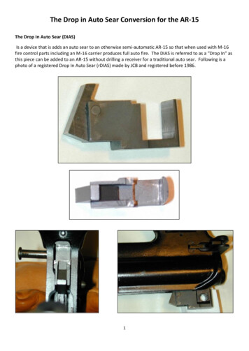
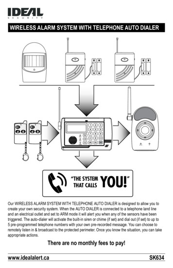
Manuals User Manuals Simplified.AUTO-VOX TW1 Truly Wireless Backup Camera Kit User ManualFebruary 21, 2022February 21, 2022Leave a commentHome » AUTO-VOX » AUTO-VOX TW1 Truly Wireless Backup Camera Kit User ManualContents [ hide1 AUTO-VOX TW1 Truly Wireless BackupCamera2 Components3 Get Started4 Installation5 Operation6 Battery Indicator7 Optional Accessory – Solar Panel8 TROUBLESHOOTING9 SPECIFICATION10 Warranty11 FCC Statement12 Documents / Resources12.1 Related Manuals / ResourcesAUTO-VOX TW1 Truly Wireless Backup Camera
ComponentsNote: The backup camera can work with optional solar panel. For more information, please refer to page 11.Get StartedCharge the CameraBefore installing your backup camera, fully charge the camera’s battery using a plug and the battery charging cable. Let the battery charge for 4-5 hours.Attention:1. If you are leaving your vehicle unused for more than half a month, press the power button on the right side to turn off the camera. This prevents thebattery from discharging.2. The backup camera can work continuously for 7.5 hours at 100% charge. If ii is being used 3 times a day ( the reversing time is 60 seconds ), the fullycharged camera can last for about 45 to 60 days. When a low battery icon flashes on the display, please charge the camera in time. (The working hoursare for your reference only, it also depends on the using environment.)3. If you use a power bank or a jump starter to charge the device, make sure that its battery capacity is no less than 5000mAh.4. If the product has been installed, you can charge the camera by battery charging cable using a mobile power supply or jumper starter. Or you canremove the camera as following instructions and then charge it.Unscrew the anti-theft screw of the camera with the equipped screwdriver;Remove the camera in the direction specified below.Test the SystemPrior to installing your backup camera, test all components in the system to ensure proper functionality. (Camera and monitor come pre-paired)1. Supply power to the monitor. If the indicator light is Iii, the monitor is on and functioning.2. Press the power button to turn on the rear camera. The indicator light will flash once. This indicates that the backup camera is on the functioning.3. Press the camera activation button on car charger or any side button on the monitor once. The indicator lights on the monitor flash twice, then themonitor will display image of the camera. In addition, the camera indicator light will remain solid. If you can not see camera image showing on themonitor, refer to the troubleshooting section of the manual.Note: By default, the monitor will stop displaying images and enter into standby mode after 60 seconds.InstallationInstall the Rear Camera
1.2.3.4.Unscrew and remove your license plate.Snap the bracket of camera into the license plate.Secure the backup camera and license plate with screws back onto the rear of your vehicle.You can also install the camera on the bottom of the license plate.Note: The installation pictures are for reference only.If ii is hard to tighten the backup camera and license plate with screws back onto the rear of your vehicle, install the camera as following steps:1. Unscrew the anti-theft screw, Slide the camera in the specified direction to separate it from the bracket;2. Install the camera bracket to your license plate and fasten screws;3. Fix the camera onto the bracket and fasten the anti-theft screw.Tear off the double-sided tape and stick ii to the front of the camera bracket. Then tear off the other side of the double-sided tape, slick the camera to aproper position on your license plate. For installation about the solar panel, please refer to page 11.Adjust the Camera AngleThe camera can be rotated up and down by 30 , you can adjust ii according to your needs.Mount the MonitorFind a mounting surface inside your vehicle where the monitor can be easily seen from the drivefs seat and does not obstruct your vision when driving. Youcan mount the monitor on your dashboard or on your windshield.Note: Before permanently mounting the monitor, test the reception of the camera signal in several locations as one may have better reception than the other.1. Clean and dry the area you will be mounting your monitor to before fixing the suction cup.2. Press the suction cup against the mounting surface and push theNote:1. For a clean installation, you can hide the charging cable into the decorative seam around the edge of the dashboard, and if necessary, bundle theadditioal wires with a cable tie.2. If the 12V/24V DC power port on your vehicle is a permanent power source and still have electricity go through after the engine is off, be sure to unplugthe car charger before leaving the vehicle in case the car battery drains outOperationDisplay Rear View1. Tum on the camera ( Please make sure the camera is fully charged, see “Charge the Camera”)2. Start your vehicle, the monitor is getting power, and then the monitor will display the rear image. (If ii doesn’t display rear image, press the button on thecar charger or any buttons on the monitor to activate the camera) StatusCamera Status Light Quick ReferenceStatusDescription Red light is off when camera is off or instandby modeRed light is on for 10 seconds and thenturns off. Camera enters standby mode Red light flashes until pairing success iscomplete While the monitor is showing the cameraima ge, the red light will remain solid.Red light flashes 2 times when thecamera is powered off.Operate the MonitorThe monitor indicators glow when the monitor is getting power, indicating that the monitor is in standby mode. Pressing any side button on the monitor youwill see rear view image.M: Menu / Return / ConfirmForward I IncreaseT : Back / DecreasePress M to access the menu. The display will show the menu for 3-5 seconds.
Press or T to increase/decrease, or switch between the following menu items:Brightness: adjust brightnessContrast: adjust contrastM/U Control: switch to Mirror/Normal/Upside/Down ImageSetting: to pair the monitor with the backup camera/choose different language/retrun to factory settings Reversing time: set the duration ofreversing display limeGuide line: activate or deactivate guide lineChoose the Size of Guidelines1.2.3.4.Set the guideline ON on menu;Press and hold M for about 4 seconds until the guidelines fiick;Press “- or T to choose from 6 different sizes;Press M to confirm.Note: The guidelines setting screen will close automatically if no operation is performed for about 5 seconds, then the settings will be saved. Pair the Cam 21.2.3.4.Press M to enter the main setting menu;Press or T switch to Setting Pair, press M to enter the pairing interface;Press or T switch to CAM 2, press M to enter pairing mode. Indicators on the monitor will flash while pairing;Press the power button to turn on the camera, press and hold the power button for 5s to start pairing. The indicator on the camera will flash whilepairing;5. The monitor will display the image of CAM 2 when pairing is successful.Note:1. The pairing timeout is the default 30s. If the pairing does not finish in 30s, the pairing screen will close automatically, and then the monitor entersstandby mode. If the pairing is failed, try again.2. The Cam 1 is pre-paired with the monitor, and ii is set as rear camera as default.Switch Cam 1/Cam 2 ChannelIf the monitor has been paired with both CAM 1 &CAM 2, and the monitor is not on any setting interface, press and hold T for 3 seconds to switch betweenCam 1 and Cam 2 display.Switching will be invalid in the following situations:When the monitor is only paired with one camera.When the monitor is paired with 2 cameras, but only one is connected successful.Note: The settings include Guide line, contrast and M / U control can be changed separately by channels. This indicates that when you change Cam 1 ‘sguidelines, it only saves in this channel instead of both channels.Confirm Version NumberWhen the monitor displays the rearview without signal indication, press and hold for 3 seconds in a non-menu state, the firmware version will be displayedin the upper and middle of the screen. The information will be automatically hidden after 3 seconds. The screen version number starts with RX and thecameras’ with TX, for example, Cam 1 is TX1: xxx, Cam 2 is TX2: xxx.Battery IndicatorThe battery icon is located in the upper right corner of the display, showing the battery level of the backup camera.Battery power RelativestatuspowerEstimatedduration[ill)100%75 days70%45 days[C)40%20 days[O20%10 daysNoteNeed to chargeNote: The parameters are tested under 25’C, low temperature may decrease the performance of the built-in battery. For reference, the chart below depictsbattery life at different temperatures at 100% charge (being used 3 times a day). However, specific battery performance will vary according to localtemperature and actual use.Temperature( Fi C)140 Ft60 c 113 F/45 C 77 Ft2s0 c 0 Fto0 c14 Ft- -4 Ft- -22 Ft10 c 20 c 30 cBatteryWorking Days75 daysBattery100%Performance(%)74 days73 days57 days50days25days0 days99%98%86%77%44%0%Optional Accessory – Solar Panel
In addition to charging the battery by USB cable, you can also use the optional accessory – solar panel to charge it. Under the condition that the solar panelcan be fully exposed to sunlight for 2 hours a day, and you are using it 3 times a day for 60 seconds each time, you should not need to charge the camera for3 to 9 months. (The charging effect of solar panel and working hours is for your reference only, it also depends on the using environment.)PackageInstall the Solar Panel1. Solar Panel and Camera Install Separate CDStick the double-sided tape on the solar panel.Unscrew and remove your license plate.Remove the cover(the antenna), and insert the solar panel plug to the camera’s micro socket. Ensure that they are connected properly.Hide the solar panel wire behind the license plate. Secure the backup camera and license plate with screws back onto the rear of your vehicle.Tear off the double-sided tape on the solar panel and then stick the solar panel on the bottom of the license plate frontside.Tips:1. You can also install the solar panel on the top of your license plate, and install the camera on the bottom. If you install the camera on the bottom of thelicense plate, please go to the setting menu and set the image’s up and down correctly to avoid image inversion necessary, you can install the solarpanel to other places near the license plate.2. Install Solar Panel onto the CameraSecure the bracket and the solar panel with screws. (Use a standard screwdriver to tighten screws.) @ Unscrew the anti-theft screw on thecamera with the equipped anti-theft screw screwdriver.Fix the solar panel onto the camera by sliding in the direction shown below.Remove the cover from the camera charging port, and insert the solar panel plug to the camera’s micro socket. Ensure that they are connectedproperly.Align the hole of the solar panel and camera, then tighten the anti-theft screw.Snap the bracket of the camera into the license plate. Secure the backup camera and license plate with screws back onto the rear of your vehicle.
Tips: If you install the camera on the bottom of the license plate, please go to the setting menu and adjust the image’s up and down correctly to avoid imageinversion.Note:1. The installation pictures are for reference only.2. Ensure that the solar panel is not covered by any objects. Otherwise, the wireless signal might be affected. {Antenna is in the solar panel.)TROUBLESHOOTINGSPECIFICATION
RFDeviceBackup CameraTransmissionDesignation KitDistance230 ft. (70 m)Storage-4 F to 149 F / - OperatingTemperature 20 C to 65″CTemperature-4 F to 149 F / 20 C to 65 CTransmissionFrame Rate25 FPSOperational MaxCurrent430mA@4.2VWorkingVoltageDC yCapacity3350mAhOperationalCurrentMax 300mA(@12V)Image Delay 150 msMultilingual EN/DE/JPCameraJX-H65Battery Type Lilhium BatteryView Angle 115 5 MonitorOperatingVoltageDC 12-24VScreen Size 5-inchWarrantyYou (as the end-user) receive a 12 months guarantee from the date of purchase. In addition, you can contact our service representative via the email addressgiven in the warranty card to obtain an extra 6 months warranty for free. If we repair or replace a product, the repaired or replaced product shall be warrantedfor the remaining time of the original warranty period. If for any quality problem not satisfied with your purchase, you shall return any item in its originalcondition within 30 days of receipt and we will gladly provide a refund, replacement, or an exchange. Any items received after 30 days will not be acceptedfor refund. For any items received after 30 days, we will provide repair service during the warranty period.Our warranty does NOT cover the following situations:1.2.3.4.5.6.Warranty expiredDamage caused by human factors, accident, misuse of the productProducts purchased from unauthorized channelsUnauthorized alternation to or change of parts or components of the productFail to provide a receipt or proof of purchasMalfunctions caused by phenomena such as fire, natural disastersFor speedy processing of your warranty claim you will need:Copy of the receipt showing the purchaseReason for the claim(description of defect).Customer support can be found at www.auto-vox.comAlternatively, send an e-mail to a service representative at service@auto-vox.comFCC StatementThis equipment has been tested and found to comply with the limits for a Class B digital device, pursuant to Part 15 of the FCC Rules. These limits aredesigned to provide reasonable protection against harmful interference in a residential installation. This equipment generates uses and can radiate radiofrequency energy and, if not installed and used in accordance with the instructions, may cause harmful interference to radio communications. However, thereis no guarantee that interference will not occur in a particular installation. If this equipment does cause harmful interference to radio or television reception,which can be determined by turning the equipment off and on, the user is encouraged to try to correct the interference by one or more of the followingmeasures:– Reorient or relocate the receiving antenna.Increase the separation between the equipment and receiver.Connect the equipment into an outlet on a circuit different from that to which the receiver is connected.Consult the dealer or an experienced radio/TV technician for help.This device complies with part 15 of the FCC Rules. Operation is subject to the following two conditions:1. This device may not cause harmful interference, and2. this device must accept any interference received, including interference that may cause undesired operation.Changes or modifications not expressly approved by the party responsible for compliance could void the user’s authority to operate the equipment.Documents / ResourcesAUTO-VOX TW1 Truly Wireless Backup Camera Kit [pdf] User ManualTW1, IK4TW1, TW1 Truly Wireless Backup Camera Kit, TW1, Truly Wireless Backup Camera KitRelated Manuals / ResourcesTruly Wireless Earphones TW-E3A User Manual
Truly Wireless Earphones TW-E3A User Manual - Optimized PDF Truly Wireless Earphones TW-E3AUser Manual - Original PDFTruly Wireless Earphones YW-E7A User ManualTruly Wireless Earphones YW-E7A User Manual - Optimized PDF Truly Wireless Earphones YW-E7AUser Manual - Original PDFYamaha TW-E7A Truly Wireless Earphones User GuideYamaha TW-E7A Truly Wireless Earphones User Guide - DownloadYamaha Truly Wireless Earphones TW-E7A User ManualYamaha Truly Wireless Earphones TW-E7A User Manual - Original PDFLeave a commentYour email address will not be published.CommentNameEmailWebsiteSave my name, email, and website in this browser for the next time I comment.Post CommentManuals ,homeprivacy
1 AUTO-VOX TW1 Truly Wireless Backup Camera 2 Components 3 Get Started 4 Installation 5 Operation 6 Battery Indicator 7 Optional Accessory - Solar Panel 8 TROUBLESHOOTING 9 SPECIFICATION 10 Warranty 11 FCC Statement 12 Documents / Resources 12.1 Related Manuals / Resources AUTO-VOX TW1 Truly Wireless Backup Camera