Transcription
Chapter17Capacitive ReactanceTopics Covered in Chapter 1717-1: Alternating Current in a Capacitive Circuit17-2: The Amount of XC Equals 1/(2πfC)17-3: Series or Parallel Capacitive Reactances17-4: Ohm's Law Applied to XC17-5: Applications of Capacitive Reactance17-6: Sine Wave Charge and Discharge Current 2007 The McGraw-Hill Companies, Inc. All rights reserved.
17-1: Alternating Current in aCapacitive Circuit Capacitive reactance is the opposition a capacitoroffers to the flow of sinusoidal current. Symbol: XC Units: Ohms Formula (this applies only to sine wave circuits):1XC 2π f CMcGraw-Hill 2007 The McGraw-Hill Companies, Inc. All rights reserved.
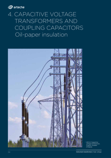
17-1: Alternating Current in aCapacitive Circuit Current flows with ac voltage applied to a seriesconnected capacitor and light bulb. There is NO current through the capacitor’s dielectric. While the capacitor is being charged by increasingapplied voltage, the charging current flows in onedirection in the conductors to the plates. While the capacitor is discharging, when the appliedvoltage decreases, the discharge current flows in thereverse direction. With alternating voltage applied, the capacitoralternately charges and discharges.
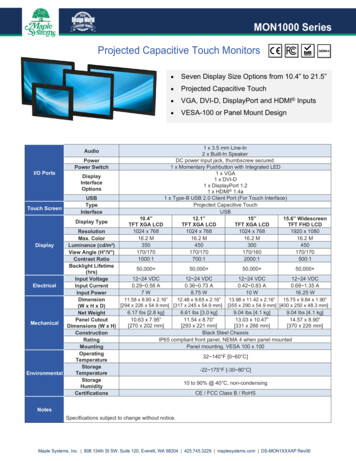
17-1: Alternating Current in aCapacitive CircuitWith a 4-µF capacitor,the bulb lights brightly.The smaller capacitor hasmore opposition to ac andthe bulb is dim.The capacitor blocksdc and the bulbcannot light.Fig. 17-1: Current in a capacitive circuit. (a) The 4-µF capacitor allows enough current I tolight the bulb brightly. (b) Less current with smaller capacitor causes dim light. (c) Bulb cannotlight with dc voltage applied because a capacitor blocks the direct current.Copyright The McGraw-Hill Companies, Inc. Permission required for reproduction or display.
17-1: Alternating Current in aCapacitive Circuit Summary: Alternating current flows in a capacitive circuit with acvoltage applied. A smaller capacitance allows less current, which meansmore XC with more ohms of opposition. Lower frequencies for the applied voltage result in lesscurrent and more XC. With a steady dc voltage source (zero frequency),the capacitor’s opposition is infinite and there is nocurrent. In this case the capacitor is effectively anopen circuit.
17-1: Alternating Current in aCapacitive Circuit Summary, cont. XC depends on the frequency of the applied voltage andthe amount of capacitance. XC is less for more capacitance. XC is less for higher frequencies.
17-2: The Amount of XCEquals 1/(2π f C) Factors Affecting XC The value of XC is inversely proportional to the value ofcapacitance: Increasing C decreases XC Decreasing C increases XC The value of XC is inversely proportional to thefrequency: Increasing f decreases XC Decreasing f increases XC
17-2: The Amount of XCEquals 1/(2π f C) Summary of the XC Formulas: When f and C are known: When XC and f are known: When XC and C are known:1XC 2π f C1C 2π f XC1f 2π C XC
17-3: Series or ParallelCapacitive Reactances Capacitive reactance is an opposition to AC, so seriesor parallel reactances are combined in the same way asresistances. Combining capacitive reactances is opposite to the waycapacitances are combined. The two procedures arecompatible because of the inverse relationship betweenXC and C.
17-3: Series or ParallelCapacitive Reactances Series Capacitive Reactance: Total reactance is the sum of the individual reactances.XCT XC1 XC2 XC3 . etc. All reactances have the same current. The voltage across each reactance equals current timesreactance.VC1 I XC1
17-3: Series or ParallelCapacitive Reactances Parallel Capacitive Reactances Total reactance is found by the reciprocal formula:1XCT 1XC1 1XC2 1XC3 . etc. All reactances have the same voltage. The current through each reactance equals voltagedivided by reactance.I C VC / X C
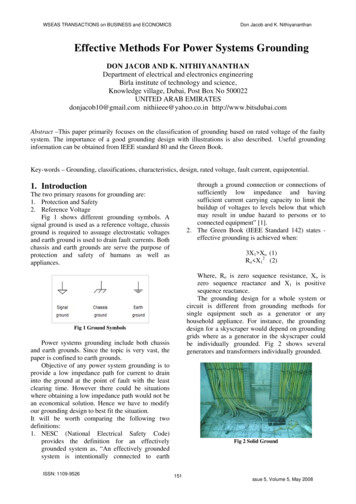
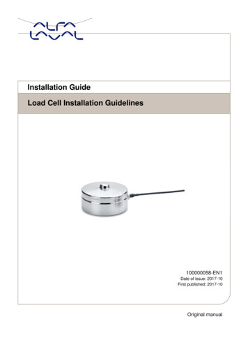
17-4: Ohm's Law Applied to XC Current in an ac circuit with XC alone is equal to the appliedvoltage divided by the ohms of XC.I V/XC 1 AI V/XCT 1/3 AIT I1 I2 1 ½ AFig. 17-6: Example of circuit calculations with XC. (a) With a single XC, the I V/XC. (b) Sum ofseries voltage drops equals the applied voltage VT. (c) Sum of parallel branch currents equalstotal line current IT.Copyright The McGraw-Hill Companies, Inc. Permission required for reproduction or display.
17-5: Applications ofCapacitive Reactance The general use of XC is to block direct current butprovide low reactance for alternating current. Ohms of R remain the same for dc or ac circuits, but XCdepends on frequency. The required C becomes smaller for higher frequencies.
17-5: Applications ofCapacitive ReactanceTable 17-1C (Approx.)Capacitance Values for a Reactance of 100 ΩFrequencyRemarks27 µF60 HzPower-line and low audio frequency1.6 µF1000 HzAudio frequency0.16 µF10,000 HzAudio frequency1600 pF1000 kHz (RF)AM radio160 pF10 MHz (HF)Short-wave radio16 pF100 MHz (VHF) FM radio
17-5: Applications ofCapacitive Reactance Summary of Capacitance vs. Capacitive Reactance: Capacitance Symbol is C Unit is F Value depends onconstruction iC C(dv/dt) Capacitive Reactance Symbol is XC Unit is Ω Value depends on C and f XC vc / ic or 1/(2πfC)
17-5: Applications ofCapacitive Reactance Summary of Capacitive Reactance vs. Resistance: Capacitive Reactance Symbol is XC Unit is Ω Value decreases forhigher f Current leads voltage by90 (Θ 90 ). Resistance Symbol is R Unit is Ω Value does not changewith f Current and voltage are inphase (Θ 0 ).
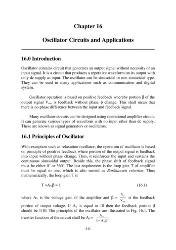
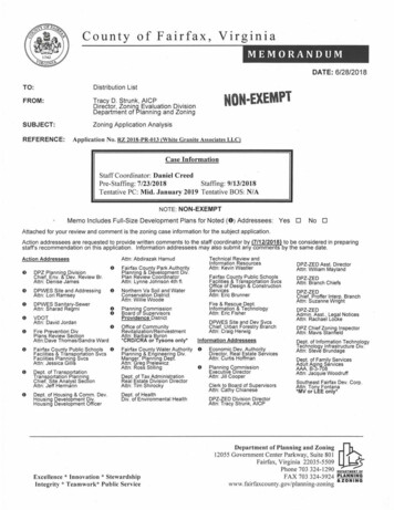
17-6: Sine Wave Charge andDischarge CurrentVA is positive andincreasing,charging C.VC decreasesby discharging.VA increases butin the negativedirection. Ccharges but inreverse polarity.Negative VAdecreases andC discharges.Fig. 17-7: Capacitive charge and discharge currents. (a) Voltage VA increases positive to chargeC. (b) The C discharges as VA decreases. (c) Voltage VA increases negative to charge C inopposite polarity. (d) The C discharges as reversed VA decreases.Copyright The McGraw-Hill Companies, Inc. Permission required for reproduction or display.
17-6: Sine Wave Charge andDischarge Current Charge and discharge current of a capacitor can befound if we know two factors:1. The capacitance value of the capacitor2. The rate of voltage change across the capacitor Capacitive current, iC depends on the rate of voltagechange across its plate
17-6: Sine Wave Charge andDischarge Current Calculating the Values of iC. The greater the voltage change, the greater the amountof capacitive current. Capacitive current is calculatedic Cdvdt i is in amperes C is in farads dv/dt volts per second.
17-6: Sine Wave Charge andDischarge Current 90 Phase Angle iC leads vC by 90 . ICE The difference results from the fact that iC depends onthe dv/dt rate of change, not v itself. The ratio of vC / iC specifies the capacitive reactance inohms.
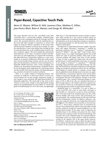
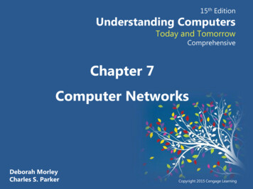
17-6: Sine Wave Charge andDischarge Currentdv/dt for Sinusoidal Voltage is a Cosine WaveVoltagedv/dtdvi CCdt0θSine waveVinst. Vmax x cos θCopyright The McGraw-Hill Companies, Inc. Permission required for reproduction or display.
27 µF 60 Hz Power-line and low audio frequency 1.6 µF 1000 Hz Audio frequency 1600 pF 1000 kHz (RF) AM radio 160 pF 10 MHz (HF) Short-wave radio 16 pF 100 MHz (VHF) FM radio. 17 -5: Applications of Capacitive Reactance Capacitance Symbol is C Unit is F Value depends on construction