Transcription
Call RecorderManualInternationalHeadquartersVIDICODE Datacommunicatie BVBlauwroodlaan 140, 2718 SK ZoetermeerThe NetherlandsTel. 31 79-3617181 Fax 31 79-3618092vidicode@vidicode.nl www.vidicode.nlUSAVIDICODE DatacommunicationsPMB 259, 1616 Shipyard Blvd.Wilmington, N.C. 28403Tel. 910.452.5600 Fax 910.254.3525vidicode@vidicode.com www.vidicode.comCall Recorder Manual -2001 Vidicode Datacommunicatie BV1
2Call Recorder Manual -2001 Vidicode Datacommunicatie BV
Contents1INTRODUCTION71.1 CONNECTING TO THE TELEPHONE NETWORK TO RECORD CALLS 891.2 CAPACITY OF THE RECORDER1.3 THE DIFFERENCES BETWEEN THE THREE TYPES OF CALLRECORDER.101.3.11.3.21.3.31.42SOME TERMINOLOGYINSTALLING THE CALL RECORDER1515151620CONFIGURING THE CALL RECORDER233.1ASPECTS OF 83.1.93.1.103.1.113.1.123.1.13412UNPACKINGMOUNTING THE HEADSET RESTCONNECTING THE CALL RECORDERTURNING ON THE POWER2.12.22.32.43The Hard Disk Call Recorder . 10The LS120 Call Recorder . 10The Flash Call Recorder . 11OPERATING THE CALL RECORDER4.14.223Recording From: . 23Setting the Start Signal . 24Signal Setting. 25Procedure for setting the signal level of speech detection . 26Setting the Telephone. 29Setting the Recorder . 29Network settings . 30Card Code. 30Quality of Recording . 30Setting the Clock. 31Setting the Password . 31Selecting the Language . 32Reset all Values . 32AUTOMATIC RECORDINGMANUAL RECORDINGCall Recorder Manual -2001 Vidicode Datacommunicatie BV3333333
4.34.4OPERATING OPTIONS WHILE RECORDINGSEARCH AND PLAY4.4.14.4.24.557INTRODUCTIONTHE DISK FUNCTIONSOPERATING A FLASH CALL RECORDER6.16.26.36.4INTRODUCTIONARCHIVINGSEARCH AND LISTENMANAGEMENT OF THE ARCHIVEOPERATING AN LS120 CALL RECORDER7.17.27.3INTRODUCTIONTHE LS120 DISKDISK 8Access to Recorder Settings. 38Card Always Needed . 38Minimum Time of Call . 39Notification Tone . 39Asking to Store or Delete . 39Beep after storage . 40Silence Period. 40Playback Volume . 40Microphone Amplification. 40Use of the Foot Switch. 41OPERATING A HARD DISK CALL RECORDER5.15.26Searching and Finding Recordings. 35The Function of the Recorder Keys Before and During Playback36RECORDER 5.94.5.103435434343454545464647474748Copying the Memory . 48Free Space on Disk . 49Verifying a Disk . 50Erasing Memory . 50Automatic Copying. 50Software Update . 51COPYING ONE RECORDINGPLAYING BACK FROM A DISKLS120 DISKS AND YOUR PC515252Call Recorder Manual -2001 Vidicode Datacommunicatie BV
8THE CALL RECORDER IN USE AS A TELEPHONE8.18.2OPERATING THE CALL RECORDER AS A NORMAL TELEPHONECONFIGURING THE TELEPHONE .2.99DESK-TOP OPERATION9.1.19.1.29.1.39.1.49.26365Introduction . 65Entering the Password. 66Listening to New Messages Remotely . 66Selecting a Different Welcome Message Remotely . 67Changing the Password Remotely. 67Changing the Welcome Message Remotely . 67Switching the Answering Machine on Remotely . 68Changing the System Messages . 6810 THE CALL RECORDER AS A NORMAL RECORDER10.1 RECORDING10.2 SEARCH AND PLAY11 THE NETWORK INTERFACE11.1 THE POSSIBILITIES11.2 CONFIGURATION11.3 USE OF THE NETWORK INTERFACE11.3.111.3.263Switching On and Off . 63Welcome Messages. 63Playing Back Messages. 64Playing Old Messages . 65OPERATING THE CALL RECORDER 58Telephone Active or not . 58Hook Flash and Earth Flash . 58Waiting after Dialling . 59Caller ID . 59K-break Detection (UK only) . 59Answering . 60The Settings of the Telephone Ring . 60Use of Speaker with Answering Machine. 61Maximum Message Time . 61THE TELEPHONE ANSWERING MACHINE9.15571717273737477The FTP protocol . 77The monitor. 77Call Recorder Manual -2001 Vidicode Datacommunicatie BV5
12 THE CRYPTO CARD OPTION12.112.212.312.4HOW A CRYPTO CARD WORKSCHANGING THE CARD CODERECORDING WITH THE CRYPTO CARDPLAYING RECORDINGS WITH THE CRYPTO CARD797980818113 ERASING A RECORDING8314 MAINTENANCE8514.1 CHANGING THE DISK DRIVE8515 POSSIBLE PROBLEMS & FREQUENTLY ASKED QUESTIONS8715.1 POSSIBLE PROBLEMS15.2 FREQUENTLY ASKED QUESTIONS878916 ACCESSORIES9117 GUARANTEE CONDITIONS9518 ADDITIONAL INFORMATION9719 INDEX996Call Recorder Manual -2001 Vidicode Datacommunicatie BV
1 IntroductionThe Call Recorder is an audio recorder with certain special features: It has been specially designed to record telephone conversations It has connections for a microphone, a telephone headset and atelephone line It records digitally It starts and stops recording automatically (or manually, if preferred) It archives the recordings to facilitate searching It highly compresses recordings, resulting in a large storage capacity It can encrypt recordings using the optional Crypto Card for a highlevel of security It can interface with computers and networks using the Ethernetinterface and TCP/IP protocol with the built-in FTP serverThe Call Recorder can be configured to automatically record from any one offive possible signal sources A telephone line that goes through the recorder A telephone conversation conducted while the Call Recorder itself isin use as a telephone A telephone line that is being monitored The telephone handset A microphoneThere are three different types of Call Recorder: The Hard Disk Call Recorder, with an internal hard disk and a highcapacity of 1950 or 3900 hoursCall Recorder Manual -2001 Vidicode Datacommunicatie BV7
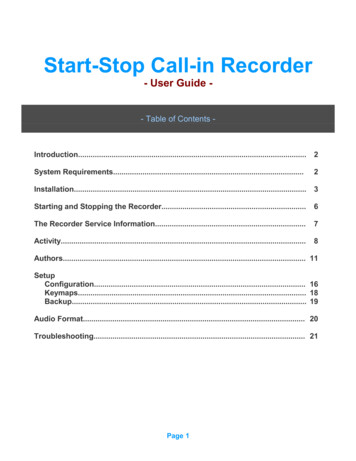
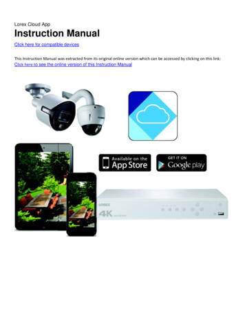
The Flash Call Recorder, with enough memory to record theoccasional conversation and a capacity of 3.5 or 7 hours The LS120 Call Recorder, with exchangeable LS120 disks eachhaving a capacity of about 32 hours.The Call Recorder can function as a recorder only, but also as a telephone ortelephone answering machine, whichever you prefer.1.1Connecting to the Telephone Network to Record CallsThere are four ways of connecting the Call Recorder to the telephonenetwork:1.As a stand-alone unit. TheCall Recorder functions as atelephone which records theconversationsconductedover it.2.In series with a s the conversations onthe normal telephone, butcan itself still be used as atelephone at any time. A callon the normal phone can bemonitored on the CallRecorder, both via theheadset and the built-inCall Recorder being used as a telephoneloudspeaker. The recorder isactivated by the line currentas soon as the handset of the telephone is taken off the hook.3.Via the handset connection of the telephone. The recorder isactivitated when words are spoken into the handset and switches itselfoff when no sound has been detected for a certain period of time.4.Parallel to a telephone line which is being monitored.Whenconnected in this way, the line is not led through the recorder, so therecorder cannot monitor the hookswitch. In principle a telephone linecould be tapped this way. It is used most often, however, to connect to a8Call Recorder Manual -2001 Vidicode Datacommunicatie BV
switchboard at some central point. The switchboard determines thebeginning and the end of the recording via the external contact. If there isno external contact the recorder is activated when people speak on theline, and de-activated when nothing has been said for some time.1.2Capacity of the RecorderThe Call Recorder can be set to operate seven different audio compressiontechniques. The standard quality is meant for storage of telephone calls, andis comparable in quality to GSM; it is the one most often used by ourcustomers.In those cases where the quality of the recordings is of special importance, itis possible to set a lower compression factor; the advantage is a significantgain in quality, the disadvantage a lower storage capacity. When onlytelephone conversations are being recorded, little is gained because thequality of the telephoneline itself is a limiting factor. High quality will make adifference, however, when one is recording a meeting, for instance.It is also possible to set a higher compression factor to raise the storagecapacity. The highly compressed G.723 Low Rate still offers an acceptablerecording quality though to most listeners it will be obvious that this is highlycompressed audio.The various compression techniques are interchangeable. All you need to dois change the settings prior to recording. When the recordings are played, therecorder will recognize the compression method used.The table below gives an overview of the capacity of every model dependanton the compression method used.Digitalk(standard)G.729G.728G.723High RateG.723Low RateNo. 1390hard diskNo. 1391hard diskNo. 1380flashmemoryNo. 1382flashmemoryNo. 1370LS120floppy1950 hours3900 hours4 hours8 hours31 hours2080 hours1040 hours2500 hours4160 hours2080 hours5000 hours4,5 hours2,25 hours5,5 hours9 hours4,5 hours11 hours33 hours16,5 hours41,5 hours3145 hours6290 hours6,5 hours13 hours50 hoursCall Recorder Manual -2001 Vidicode Datacommunicatie BV9
G.711 ALawG.711 µLaw1.3260 hours260 hours520 hours520 hours0,5 hours0,5 hours1 hours1 hours4 hours4 hoursThe differences between the three types of Call Recorder.The table above shows that there are three different types of Call Recorder:one with a hard disk, one with an internal flash memory and one with anexchangeable LS120 disk. Each type of recorder treats the medium it recordsfrom in a different way. The capacity of the storage medium has noconsequences for the way a Call Recorder operates. A recorder with a harddisk of limited capacity operates in exactly the same way as one with a highcapacity, for instance.1.3.1The Hard Disk Call RecorderA Call Recorder with a hard disk will automatically create space for newrecordings by erasing the oldest ones when the disk is close to full capacity.This should be taken into account, and recordings that need to be kept longershould be archived. It should present no practical problems, because thecapacity of this type of recorder is sufficient to store conversations of severalyears.The maximum number of recordings that can be stored in the recorder with ahard disk is 500,000 for all models, which means there are no practicalrestrictions.When after several years of use the hard disk is approaching its full capacity,the recorder will give a warning signal well in time for the user to check ifthere are any objections to the oldest recordings being overwritten.1.3.2The LS120 Call RecorderAn LS120 Call Recorder not only has the capacity of the floppy disk at itsdisposal, but also an internal flash disk, which is equal to that of article no.1280 (flash disk 16Mb). This implies that when the floppy disk is full, somefour hours of recording time will be left, leaving ample time to place a newdisk in the recorder.10Call Recorder Manual -2001 Vidicode Datacommunicatie BV
The Call Recorder with a LS120 drive makes all its recordings in the (flash)memory. Every night these recordings are automatically stored on the LS120disk. When space is about to run out, a warning will appear on the display,and a new LS120 should be placed in the disk-drive of the recorder.It is also possible to manually copy the recordings onto the LS120 disk, In thisway several copies can be made, if this is required.The maximum number of recordings that can be kept on an LS120 disk is2048.1.3.3The Flash Call RecorderThe Flash Call Recorder has two important areas of application: applications in which recordings only occasionally need to be storedpermanently Applications in which the computernetwork continually centrally archivesrecordings (e.g. at least once a day)In the first application the capacity has therefore been split into two parts,unlike the Hard Disk Call Recorder.One half of its memory works just like a Hard Disk Call Recorder, continuallyoverwriting the oldest recordings. The other half of the memory serves as anarchive. A recording in the archive will be kept until it is erased by the user.By pressing on the red button, for instance, the user is able to place arecording in the archive.When the archive is about to reach its limit, i.e. no more than 30 minutes ofstandard quality recording can be added, a warning will be displayed on thescreen. Recordings will need to be erased, but before this is done, they canbe archived in a PC.In the second application this type of recorder works just like a Hard Diskrecorder. Its entire capacity is utilised, and when the memory is full up, theoldest recordings will be overwritten. It is essential that our Call RecorderArchive Software has been installed on the network and automaticallyarchives the recordings at least once a day. In the case of automaticarchiving, using a Flash Call Recorder is more economical than using a HardDisk Call Recorder.Call Recorder Manual -2001 Vidicode Datacommunicatie BV11
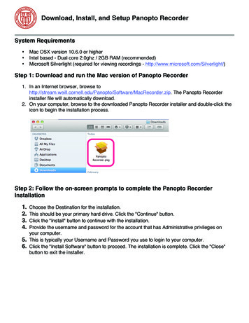
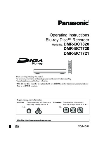
There is no limit to the number of recordings in this type of Call Recorderother than the capacity of the memory.1.4Some TerminologyFor clarity the following terms are used to refer to the recorder’s controls:1: LCD or displayThe screen that gives the user information2: SoftkeysThe keys under the display that perform thefunction on the display3: Telephone keysThe keys 0 and 1 to 9, * and #4: Function keysThe keys with their function shown above them as12Call Recorder Manual -2001 Vidicode Datacommunicatie BV
a pictogram5: Recording keysThe keys,,,,andto those on a cassette or video recorder, similarThe following terms are used to describe the recording keys:Record keyRewind keyStop keyPlay keyFast forward keySpecial Call Recorder key for selecting the next recordingThe following are the function keys:Telephone keyLoudspeaker keyTelephonebook keyDisk key (for model with hard disk or flash disk)Disk key (for model with LS120 floppy disk)Call Recorder keyAudio Recorder keyCall Recorder Manual -2001 Vidicode Datacommunicatie BV13
Answering Machine keyMenu (Configuration) key14Call Recorder Manual -2001 Vidicode Datacommunicatie BV
2 Installing the Call Recorder2.1UnpackingThe Call Recorder comes supplied with the following parts:2.2 headset mains supply adapter telephone cable with 2 jack plugs having six contacts adapter plug for the local telephone network, when applicable short coiled telephone cable with 2 jack plugs having 4 contacts metal rest for the headset, and a small plastic bag with two screwsand rings for mounting it this manual one LS120 disk (only with model 1370)Mounting the Headset RestThe headset rest has two square corners on one side. These should bepressed firmly into the L-shaped groove at the bottom of the recorder, andthen tightly screwed in with the two screws and rings supplied.Call Recorder Manual -2001 Vidicode Datacommunicatie BV15
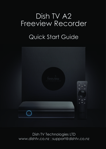
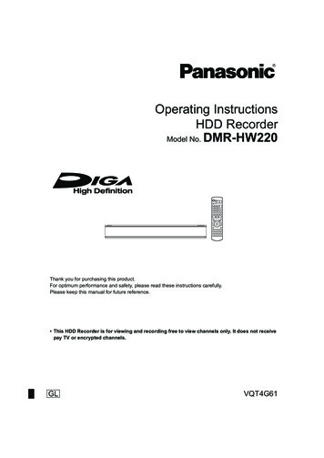
2.3Connecting the Call RecorderThe way the Call Recorder is connected depends upon the intended use. Theavailable connections are listed below.ABCDEFGConnection for a footswitch and/or start recording switchConnection for external mains supplyConnection for headset/microphone/external speakersConnection for link to computerConnection to a 10BaseT ethernet hub/switchConnection for recording via the handset of the telephoneConnection for recording via telephone and telephone lineEvery application requires the following connections to be made:BCConnect the external mains supply adapter to BConnect the headset to CThe use of the headset itself is not compulsory. A separate microphone, ormulti media speakers, could be connected to the headset/microphone port aswell.Use as a TelephoneIn this application the Call Recorder itself is used as the only telephone. Thisis possible when there is an analog telephone connection for non-systembound telephones. When the Call Recorder is used in this way it should beconnected as follows:G16Connect the telephone line to the ‘LINE’ portCall Recorder Manual -2001 Vidicode Datacommunicatie BV
The telephone cable with the RJ12 jacks that comes supplied with the CallRecorder should be used for this. It is an American type of cable that isbecoming increasingly popular outside America.If you still have an old-fashioned wall socket, the telephone cable can beconnected with the adapter supplied.Use in Combination with an Analog TelephoneIn this application the Call Recorder and the telephone stand side by side.The following should be connected:GConnect the telephoneline to the ‘LINE’ portConnect the telephone to the ‘PHONE’ portIf you have a normal analog extension, you will now be able to use both therecorder and the telephone for making calls. All calls will be recorded.If your phone has been equipped with a special local plug, it can easily beconnected onto the adapter plug supplied.Use in Combination with a System-Bound Analog TelephoneIn this application the Call Recorder and telephone stand side by side. Thefollowing should be connected:GConnect the telephoneline to the ‘LINE’ portConnect the telephone to the ‘PHONE’ portIf you own a telephone that is system-bound (i.e. that is part of the in-housetelephone network) but is analog in its functioning, only the phone can beused for making calls, not the recorder. The recorder will record all calls madeCall Recorder Manual -2001 Vidicode Datacommunicatie BV17
on the telephone. There is a possibility that the recorder will not alwaysregister the numbers you dial.If your phone has been equipped with a special local plug, this can easily beconnected onto the adapter supplied.Use with Entirely Digital and ISDN TelephonesIn this application the recorder and the telephone stand side by side. Whenused in this way the recorder taps the conversation on the cable between thetelephone and the telephone handset. The following should be connected:FDisconnect the cable of the telephone handset from the side ofthe phone, and connect it to the ‘HANDSET RECORDING’ - ‘tohandset’ portUse the short cable supplied to connect the old connection tothe telephone handset on the phone to the ‘HANDSETRECORDING’ - ‘to base’ portIf you have a modern telephone, the cable of the handset will fit straightaway.You might own a telephone with an integral cable, in which case a specialcable may need to be made. Alternatively you could possibly swap yourphone with someone else’s in your firm who owns a more modern model.Note: This method of connecting may mean that two jumpers within therecorder have to be adjusted. They can be found at the back of the recorderand are marked: JP3.JP3 enables you to adapt the Call Recorder to a different wiring from the cablebetween your telephone and telephone handset. Normally the inner two wiresserve the loudspeakers, while the outer two serve the microphone, or the otherway round: so either MLLM or LMML. In this case the jumpers JP3 are in thecorrect position.18Call Recorder Manual -2001 Vidicode Datacommunicatie BV
The alternative is that the pairs of wires lie next to each other, according to theschedule MMLL. If that is the case, the recorder can be adjusted by placingboth the jumpers on JP3 that are normally directed towards the left side (on pin1 and 2 and on pin 4 and 5) of the recorder so that they directed to the rightside of the recorder (that is on pin 2 and 3 and on pin 5 and 6).In order to do so it is necessary for you to open the recorder. If this is toodifficult for you, your supplier will gladly assist you.NB: You may have noticed that this way of connecting works for every type oftelephone, so should be the preferred one. There are two drawbacks to thismethod, however. One is that the recorder cannot distinguish between a freeand an engaged telephone line, and will stop recording when there is a longishpause, for instance when you walk away from your telephone to get something,occasionally resulting in two recordings of one conversation. The otherdrawback is that the recorder cannot be used as an answering machine ortelephone when connected this way.Use as a Normal Audio RecorderWhen the Call Recorder is in use as a recorder, apart from the power supply,only the normal audio connections are used, i.e. ‘HEADSET mic’(microphone) and ‘HEADSET ls’ (loudspeaker).Use of the Footswitch (option)The only additional connection needed is:AConnect the footswitch to the ‘SWITCH’ portUse of an External Contact as Start SwitchThe only additional connection needed is:AConnect the external switch to the ‘SWITCH’ portConnecting to the PC (with optional PC software)If you have PC software for the Call Recorder, the PC should be connectedas follows:Call Recorder Manual -2001 Vidicode Datacommunicatie BV19
For a direct serial connection:DConnect the PC cable to the ‘PC’ port on the Call Recorder, and toCom 1 or Com 2 on the PCThe throughput of a serial connection is rather slow but this type ofconnection can be made with almost any PCFor a connection over the LAN or internet:EConnect the ethernet port of the recorder with a hub or switch ofyour network using a standard network patch cableThis is the preferred way for an office environment with several recorders.For a direct connection between the ethernet port of the recorder andthe ethernet port of a PCEConnect the ethernet port of the recorder with the ethernet port ofthe PC using a special crossover cableIn this way a very fast connection between a PC and a recorder can beestablished for applications where there is only one PC and one recorder.When such a fast connection is required but the PC has no ethernet card butdoes have a USB port, as is common on notebook PC’s, a USB to ethernetadapter can bridge the gap and offer a cost efficient high speed connection.2.4Turning on the powerConnect the mains supply adapter to the mains. The display will show thefollowing text:RESETFollowed by:INIT20Call Recorder Manual -2001 Vidicode Datacommunicatie BV
Ending with for instance:Monday19-08-01 10:53Call RecorderSometimes the following message is displayed:Monday01-01-00 00:00***The clock is Wrong***This means that the clock has not been configured yet, and should first be setto the right date and time. How to do this is explained in the next chapter,which covers configuring the Call Recorder.Call Recorder Manual -2001 Vidicode Datacommunicatie BV21
22Call Recorder Manual -2001 Vidicode Datacommunicatie BV
3 Configuring the Call RecorderA newly installed Call Recorder needs to be configured for the desired. You willapplications. The configuring menu can be reached by pressingthen be asked to answer a few important configuring questions, regarding theclock, for example, or, in one of the sub-menus, the telephone settings.In this chapter only configuring the recorder for use as a call recorder isdiscussed.3.1Aspects of ConfiguringAccess to the recorder may have been secured with a password. At deliverythis is not yet the case.When installing, you will find the options represented by the softkeysindicated on the display. You can scroll through the options with the recorderkeys.selects the previous menu functionselects the next menu function (similar to ‘NEXT’)3.1.1PressRecording From:and you will see:Record from : LineNEXTCHANGESTOPThis selects the source from which the recorder will automatically record.By repeatedly pressing the ‘CHANGE’ softkey, you can select one of threepossible sources: Line, if the telephone line has been connected to the recorderCall Recorder Manual -2001 Vidicode Datacommunicatie BV23
Handset, if the handset has been connected to the recorder Microphone, if you want to record automatically from themicrophoneThe recorder can only record automatically if the source of the signal hasbeen correctly set.3.1.2Setting the Start SignalThe display will show:Start:NEXTSeries off-hookCHANGESTOPIt is important to know which signal the recorder uses to start and stop arecording. These are the possibilities:Phone in seriesThe telephone has been connected to the Phone port of the recorder. Therecorder reacts to the current that flows from the telephone exchange to theappliance when the handset is taken off the hook, which is an extremelyreliable method. However, it can only be used when one is recording from theline.Phone in parallelIn this case the recorder and the phone have been connected in parallel. Therecorder reacts to the voltage level. It is another very accurate way ofdetermining the beginning and end of a telephonce conversation. The hugedrawback of this method, however, is that recording starts as soon as theconnection between the recorder and the line is interrupted. For this reason itis recommended that it should only be used when the recorder has to listen toa line that may not be led via the recorder. This method can only be usedwhen recording from the line.24Call Recorder Manual -2001 Vidicode Datacommunicatie BV
Speech detectionIn this case the recorder reacts to a signal on the line. Speech detectionshould be used in combination with “Signal Setting”, which is discussedbelow. Speech detection is not advisable when one is recording from the line,as the recorder might be set off by not just speech, but by any other signal onthe line, such as a ring from the phone.Opening contact or Closing ContactThese settings are used when the “Switch” port of the recorder is connectedto an external contact such as can be found in various telephone exchangesand apparatuses. Recording starts whenever the external contact opens orcloses.ManuallyOf course it is also possible to start recordings manually. When manualrecording has been selected, recording is started by pressing the Recordbutton and stopped by pressing the Stop button. Note: This setting is anexception because the normal function of the Record button is not to start amicrophone recording, but to answer the question from which source one isrecording: line, handset or microphone.3.1.3Signal SettingThis question concerns the level of the signal above which the recorder willautomatically start to record. Only when speech detection has been selectedin the preceding question will the following question be shown on the display:NEXTSignal SettingCHANGESTOPTo set this select ‘CHANGE’ and the signal level measure will appear on thedisplay:A4 : BACKCall Recorder Manual -2001 Vidicode Datacommunicatie BV25
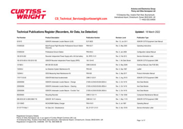
Any signal made now will be graphically represented in the following way:A4 BACKA signal beyond the bar is sufficient to start the recorder, with the barindicating the minimum signal level necessary for recording to start. Thecolon indicates the switch-off level. Recording stops when the signal staysbelow the switch-off level for a certain time (manufacturer’s setting is 10seconds). Normally the switch-off level will be lower than the switch-on level,so that recording will take pl
6 call recorder manual -2001 vidicode datacommunicatie bv 12 the crypto card option 79 12.1 how a crypto card works 79 12.2 changing the card code 80 12.3 recording with the crypto card 81 12.4 playing recordings with the crypto card 81 13 erasing a recording 83 14 maintenance 85 14.1 changing the disk drive 85 15 possible problems & frequently asked questions87