Transcription
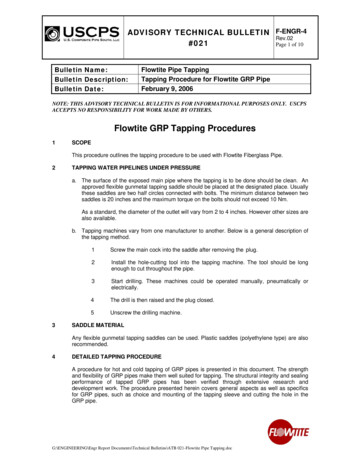
ADVISORY TECHNICAL BULLETIN F-ENGR-4Rev.02#021Page 1 of 10Bulletin Name:Bulletin Description:Bulletin Date:Flowtite Pipe TappingTapping Procedure for Flowtite GRP PipeFebruary 9, 2006NOTE: THIS ADVISORY TECHNICAL BULLETIN IS FOR INFORMATIONAL PURPOSES ONLY. USCPSACCEPTS NO RESPONSIBILITY FOR WORK MADE BY OTHERS.Flowtite GRP Tapping Procedures1SCOPEThis procedure outlines the tapping procedure to be used with Flowtite Fiberglass Pipe.2TAPPING WATER PIPELINES UNDER PRESSUREa. The surface of the exposed main pipe where the tapping is to be done should be clean. Anapproved flexible gunmetal tapping saddle should be placed at the designated place. Usuallythese saddles are two half circles connected with bolts. The minimum distance between twosaddles is 20 inches and the maximum torque on the bolts should not exceed 10 Nm.As a standard, the diameter of the outlet will vary from 2 to 4 inches. However other sizes arealso available.b. Tapping machines vary from one manufacturer to another. Below is a general description ofthe tapping method.31Screw the main cock into the saddle after removing the plug.2Install the hole-cutting tool into the tapping machine. The tool should be longenough to cut throughout the pipe.3Start drilling. These machines could be operated manually, pneumatically orelectrically.4The drill is then raised and the plug closed.5Unscrew the drilling machine.SADDLE MATERIALAny flexible gunmetal tapping saddles can be used. Plastic saddles (polyethylene type) are alsorecommended.4DETAILED TAPPING PROCEDUREA procedure for hot and cold tapping of GRP pipes is presented in this document. The strengthand flexibility of GRP pipes make them well suited for tapping. The structural integrity and sealingperformance of tapped GRP pipes has been verified through extensive research anddevelopment work. The procedure presented herein covers general aspects as well as specificsfor GRP pipes, such as choice and mounting of the tapping sleeve and cutting the hole in theGRP pipe.G:\ENGINEERING\Engr Report Documents\Technical Bulletins\ATB 021-Flowtite Pipe Tapping.doc
ADVISORY TECHNICAL BULLETIN F-ENGR-4Rev.02#021Page 2 of 104.1 INTRODUCTORY INFORMATIONThis procedure is intended to assist the installer and owner of GRP pipe systems inunderstanding the requirements and the procedures for successful mounting of tapping sleeveson existing pipelines. Tapping is convenient for fitting a branch pipe or valve to an alreadyexisting pipeline where it is not practical to use a standard GRP nozzle or tee fitting. Theprocedure covers both hot and cold tapping.This tapping procedure is founded on extensive research and development work. A series ofshort and long term pressure tests as well as FEM analysis was performed for qualification of atapping sleeve for use on a GRP pipe. Stainless steel material is selected as the material for thetapping sleeves to get a service life similar to that of the GRP pipe system. Not all types oftapping sleeves are suitable for this service.This tapping procedure applies for all properly installed standard GRP pipes carrying water orwater based fluids. The tapping sleeve shall be placed in an area with low local axial pipestresses. Extra support may be needed for above ground pipes.The following definitions apply: Hot tapping: Installation of a nozzle or branch pipe on an existing pressurized or fluid filledGRP pipeline using a steel sleeve. Cold tapping: Installation of a nozzle or branch pipe on an existing empty and nonpressurized GRP pipeline using a steel sleeve.Flexible stainless steel sleeves (see Figure 1) are recommended for tapping into GRP pipes.Approved tapping sleeves suitable for GRP pipes are given in Table 1.Figure 1: Recommended tapping sleeves for GRP pipesIt is recommended to engage tapping experts for both hot and cold tapping jobs. The tools forperforming the hot and cold tapping may vary.For hot tapping, the sleeve is mounted on the pressurized pipe. A valve and a tapping machinecontaining the cutter are mounted on the sleeve. The valve is opened and a hole drilled. Thecutting device is then retracted, the valve closed and the tapping equipment is removed leavingthe sleeve and the closed valve. A branch pipe can then be fitted on the valve and the valveopened.For cold tapping, a branch pipe hole is drilled in a non-pressurized pipe. The tapping sleeve isthen mounted around the pipe with the branch aligned with the hole. A branch pipe or valve canG:\ENGINEERING\Engr Report Documents\Technical Bulletins\ATB 021-Flowtite Pipe Tapping.doc
ADVISORY TECHNICAL BULLETIN F-ENGR-4Rev.02#021Page 3 of 10then be fitted to the tapping sleeve. – The procedure for hot tapping can also be used for coldtapping.4.2 SELECTION AND USE OF TAPPING SLEEVESGRP approved tapping sleeves are given in Table 1.Table 1: Approved Tapping Sleeves and Gasket TypeSleeve TypeDimensionsPressure ClassGasket TypeSupplierRomacon SST(Stainless-steeltapping sleeve)Up to DN30”Up to 250 psi workingpressure.SBR RubbergasketRomaconPipelineProducts B.V.www.romacon.nlTel: 31 77 3549116The maximum tapping branch pipe diameter shall be limited to: 20 % of header pipe diameter for SN18 pipe. 25 % of header pipe diameter for SN36 pipe. 30 % of header pipe diameter for SN72 pipe.Maximum surge (water hammer) pressure that can arise in the pipeline must be accounted for inthe selection of tapping sleeve pressure rating.The tapped system is qualified for vacuum corresponding to the pipe stiffness.The tapping sleeves are designed to closely fit the outer diameter of the pipe. The tapping sleevewill therefore need to match the outer diameter of the GRP pipe.Thrust that the tapped system may generate must be balanced.The location of the sleeve shall at a minimum be: A length of not less than one pipe diameter away from the nearest coupling and/or fitting. The tapping sleeve shall be placed in an area with low local axial pipe stresses. Extrasupport may be needed for above ground pipes.4.3 TAPPING PROCEDURESCare must always be exercised when working with pressurized systems. This is especially truefor hot tapping, where pressurized media is irreversibly exposed. Expert advice and proficiencyshould always be sought in such cases.When working in trenches, precautions should be taken to prevent objects from falling into thetrench, or its collapse caused by instability or the position or movements of adjacent machinery orequipment.This procedure covers preparation, mounting, bolt torques, cutting, inspection, and testing.G:\ENGINEERING\Engr Report Documents\Technical Bulletins\ATB 021-Flowtite Pipe Tapping.doc
ADVISORY TECHNICAL BULLETIN F-ENGR-4Rev.02#021Page 4 of 104.3.1 PreparationsAdequate access for mounting the tapping sleeve and the tapping machine must beprovided. The pipe must be uncovered if buried. The pipe shall be cleaned thoroughlyprior to mounting the tapping sleeve. Loose particles, dust, sand, and grease, etc. shallbe removed. Normally, no further surface preparation is necessary.The pipe surface shall be inspected for damage in the area underneath and adjacent tothe tapping sleeve after cleaning. No damage to the pipe is acceptable in this area.4.3.2 TappingHot and cold tapping procedures are covered below.4.3.2.1 Hot TappingFor hot tapping, a specialized tapping machine is always required. In addition to thetapping sleeve and machine, the assembly consists of a branch valve (gate or ball) andthe cutting device (see Figure 3). The pressure rating of the branch valve and the tappingequipment shall be at least equal to the pressure rating of the pipeline.For hot tapping the following procedure shall be followed:1. The tapping sleeve shall be located and oriented according to the plans and/ordrawing.2. Mount the tapping sleeve on the pipe. The installation instructions issued by thetapping sleeve manufacturer for the tapping sleeve shall be used except for the bolttorque. Bolt torques applicable for GRP pipes, are given in Section 4.3.2.3.3. Mount the valve on the tapping sleeve. Follow the instructions for the valve or flangeassembly with respect to bolt torque, seal type, etc.4. Pressure test to verify sealing of tapping sleeve and valve is recommended prior totapping. It should be noted that a test with overpressure between sleeve and pipe ismore demanding on the rubber seal than a pressure test of the tapped pipe. If the tapping sleeve is equipped with a test plug, this test can be conducted withthe branch valve closed. Otherwise a blind flange with test plug can be mountedon the valve and the test conducted with open valve. Some tapping machines areequipped with a test plug rendering the blind flange superfluous. Fill the space between the pipe and the tapping sleeve with water, see Figure 2,evacuate entrapped air and pressurise to test the integrity of the seals betweenthe sleeve and the pipe and between the sleeve and the valve. The test pressureneed not exceed the actual internal pressure of the pipe to be tapped by morethan 3 bars. (If a leak occurs, dismount and inspect for dirt or damage. Do notincrease the bolt torque on the sleeve). – The test pressure shall also neitherexceed the maximum test pressure rating of the tapping sleeve nor the pipe, seeSection 4.3.3.5. Mount the tapping machine on the valve. Follow the instructions for the tappingmachine or flange assembly with respect to bolt torque, seal type, etc.6. Make sure that the valve is open and perform the cutting operation, see Figure 3.Detailed instructions for cutters and cutting are given in Section 4.3.2.4.7. After cutting, the cutting device with the coupon is retrieved through the valve. Thetapping machine with the cutting tool along with the pipe coupon can be removedonce the valve is closed (see Figure 4).8. Inspection and hydrostatic test of the assembly can be performed upon completion ofinstallation. See details in Section 4.3.3.G:\ENGINEERING\Engr Report Documents\Technical Bulletins\ATB 021-Flowtite Pipe Tapping.doc
ADVISORY TECHNICAL BULLETIN F-ENGR-4Rev.02#021Page 5 of 10Figure 2: Pressure testing of sleeve and valve assemblyFigure 3: Tapping assembly and hot tapping cuttingG:\ENGINEERING\Engr Report Documents\Technical Bulletins\ATB 021-Flowtite Pipe Tapping.doc
ADVISORY TECHNICAL BULLETIN F-ENGR-4Rev.02#021Page 6 of 10Figure 4: Tapping machine, valve and retrieved couponTapping machine with cutting deviceClosed valveCutting motorTapping machine with cutting devicePipe wall coupon.ValveTapping sleeve4.3.2.2 Cold TappingFor cold tapping the following procedure shall be followed.1. The tapping sleeve shall be located and oriented according to the plans and/ordrawing.2. The hole may be cut in advance or after mounting the tapping sleeve for coldtapping. Detailed instructions for cutting are given in Section 4.3.2.4.3. The steel sleeve shall be mounted around the existing pipe such that the sleevebranch tapping hole is aligned with the hole in pipe.4. The procedure issued by the tapping sleeve manufacturer for mounting of the tappingsleeve shall be followed except for the bolt torque. Bolt torques applicable for GRPpipes are given in Section 4.3.2.3.5. The sealing between the tapping sleeve and the pipe wall may be tested prior tocutting the hole. Follow the pressure test procedure for hot tapping given in Section4.3.2.1.6. The valve or branch pipe can be installed after cutting and assembly of the sleeve forthe cold tapping.7. Inspection and hydrostatic test of the assembly can be performed upon completion ofinstallation. See details in Section 4.3.3.G:\ENGINEERING\Engr Report Documents\Technical Bulletins\ATB 021-Flowtite Pipe Tapping.doc
ADVISORY TECHNICAL BULLETIN F-ENGR-4Rev.02#021Page 7 of 104.3.2.3 Bolt TorqueThe flexibility and pressure expansion of GRP pipes significantly enhances the sealingperformance of a tapping sleeve compared to mounting on rigid pipes like steel or ductileiron. The bolt torque required for mounting of tapping sleeves on GRP pipes is thus lowerthan for inflexible materials, and high torques may indeed be harmful for the system. Therecommended bolt torque for tapping of GRP pipes are given in Table 2. Higher bolttorques are not recommended.Table 2: Bolt torque for hot and cold tapping of GRP pipes.Sleeve TypeRomacon SST(Stainlesssteeltapping sleeve)BoltDimensions(mm)Torque(Nm)M1670CommentThe bolt torque is lower for GRPpipes than for steel pipes.4.3.2.4 CuttingCutting tools suitable for cutting of GRP pipe shall be used for cutting the tapping holes.The cutting tool must give a clean cut without tearing or breaking the pipe wall. This isespecially important when the cutting device penetrates the inner surface of the GRP pipeto avoid peeling.The following shall be observed with respect to cutting the tapping hole: A special diamond coated cutting device for glass fibre laminates is recommended (seeFigure 5). A closely spaced thin-walled fine tooth steel cutting device may also beused (see Figure 6); however, this type of device tends to wear out fast. Advancement rate of the cutter during drilling must be limited to avoid damage andpeeling of the inner surface. A test cut on a pipe wall sample is recommended foroperators and tools not previously exposed to GRP pipes (see Figure 8). The cut surface may be left as it is after cutting without further surface preparations.G:\ENGINEERING\Engr Report Documents\Technical Bulletins\ATB 021-Flowtite Pipe Tapping.doc
ADVISORY TECHNICAL BULLETIN F-ENGR-4Rev.02#021Page 8 of 10Figure 5: Recommended diamond coated cutting deviceFigure 6: Alternative cutter with closely spaced teethG:\ENGINEERING\Engr Report Documents\Technical Bulletins\ATB 021-Flowtite Pipe Tapping.doc
ADVISORY TECHNICAL BULLETIN F-ENGR-4Rev.02#021Page 9 of 10Figure 7: Unsuitable cutter with widely spaced teeth. This cutter has few widely spaced teeth and tearsglass fibers from the laminate.Figure 8: Test cut on pipe wall sample to adjust cutting speed and advance rate4.4 INSPEC
4.3.2.1 Hot Tapping For hot tapping, a specialized tapping machine is always required. In addition to the tapping sleeve and machine, the assembly consists of a branch valve (gate or ball) and the cutting device (see Figure 3). The pressure rating of the branch valve and the tapping equipment shall be at least equal to the pressure rating of the pipeline. For hot tapping the following procedure shall be followed: