Transcription
Introduction to Control andInstrumentationCourse No: E04-037Credit: 4 PDHManuel Gooding, P.E.Continuing Education and Development, Inc.22 Stonewall CourtWoodcliff Lake, NJ 07677P: (877) 322-5800info@cedengineering.com
INTRODUCTION OF CONTROL AND INSTRUMENTATIONINTRODUCTION TO CONTROL ANDINSTRUMENTATIONCopyright 2010, Manuel GoodingPage 1 of 40
INTRODUCTION OF CONTROL AND INSTRUMENTATIONTABLE OF CONTENTSError! Bookmark not ontrol System4Process Control4Variables4Control Loop4CONTROL LOOP DESCRIPTION, ELEMENTS, AND TYPES5Open Loop5Closed Loop5Comparison between Closed and Open Loops6Elements of a Control Loop7PRIMARY SENSORS9Instrument Characteristics9PRESSURE10Definition10Atmospheric Pressure12Gauge, Absolute and Differential Pressure12Other pressure units12Pressure Sensors13Pressure Instrument Calibration14Pressure Instruments Figures15Definitions18Temperature Sensors19Temperature Sensors – Length Based19Electrical Based Temperature Sensors21LEVEL23Level Sensors23Level Sensor and Transducers Figures26FLOW28Flow instruments28Figure 19 – Pressure tube location for DP measurementsOther Methods forMeasuring Flow Rate30MOTOR CONTROLS33Introduction33Motor Controllers33Motor Control Elements35Starters36Modern Automatic Motor Controls39Copyright 2010, Manuel GoodingPage 2 of 40
INTRODUCTION OF CONTROL AND INSTRUMENTATIONINTRODUCTIONThis course will present the following areas of control and instrumentation:1) Control Loop definition, elements, and types2) Study of elements of the control Loop:a) Set point, controllers, and amplifiersb) Sensors and transducersc) Instrument and measurementsd) Motors, valves, and actuatorse) Final Control Elementsi) Electrical such as heaters, generators, etc.ii) Mechanical such as valves, levers, etc3) Basic of motor controls4) Control circuit diagramsInstrumentation and control is the nervous system of industrial complexes, powergeneration, and basically all the processes that require some intelligence to accomplishthe task of producing a product or process.When a process is modified to improve its function, the best and most economic changeof the system is to improve the control and occasionally the instrumentation areas.Quality, quantity, and efficiency are directly related to the control and instrumentationsystems. The efficiency of the controls reflects directly in the profitability and quality ofthe product or service obtained from a process or system.Examples of other benefits obtained by applying control systems are evident inenvironmental controls, which help to manage the waste and regulate the interfacebetween the system and the environment. One application in this area is seen in control ofemissions which use specialized instruments and controls to decrease the impact ofpollutants in the atmosphere.The growth of the computer industry and its techniques has provided expandingtechnology in the controls area, consequently producing more efficient and sophisticatedsystems. These systems now control more precisely the production of goods andinformation given to operators to refine the quality of products and services.This course will walk you through the elements that make a control system and present toyou the most common instrumentation used in industry.Copyright 2010, Manuel GoodingPage 3 of 40
INTRODUCTION OF CONTROL AND INSTRUMENTATIONDefinitionsInstrumentation:Use of technology and devices to detect and control physical and chemical characteristicsof materials; this includes motion, light, color, acidity, etc.Control SystemA system that takes the information from instruments of a process manipulating it usinglogic (algorithms) then applying the results to a process or system to change itscharacteristics.Process ControlA control system that is used in the process and chemical industries. A process controlhas the characteristic of automatically regulating a process. Automatic in this contextmeans that the process is controlled without the need of human intervention.VariablesAre defined as the characteristic of the process. Some variables are temperature, speed,humidity, viscosity, density, etc. There are two basic types of variables: measured orcontrolled, and manipulated.Control LoopControl loop is a control system architecture that will manage a process using elementsthat sense, adjust, and act upon the process. We can define it as the configuration bywhich the control system manipulates the control parameters.Copyright 2010, Manuel GoodingPage 4 of 40
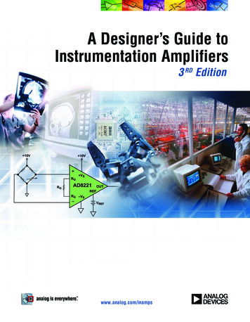
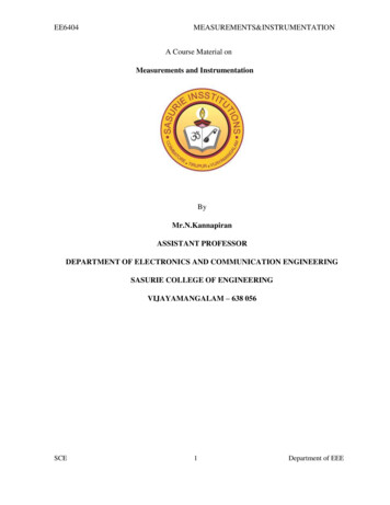
INTRODUCTION OF CONTROL AND INSTRUMENTATIONFigure 1CONTROL LOOP DESCRIPTION, ELEMENTS, ANDTYPESOpen LoopThe control loop configuration should be open, as in the control of a valve to open. Thecontroller receives the signal to open the valve. That operation is completed withoutadditional action. The loop is open because it starts at the open command and ends at thevalve opening. This is known as an open-ended control.Closed LoopA closed loop defines the action of sending a signal to a modulating valve to open it halfway; the controller applies the open signal until the valve reaches the half way point. Theposition of the valve is determined by an instrument that detects the position and sendsthe signal back to the controller to close the loop. The loop is made from the controller tothe valve actuator to the position device to the controller. See Figure 1 for a closed loopcontrol.Copyright 2010, Manuel GoodingPage 5 of 40
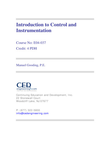
INTRODUCTION OF CONTROL AND INSTRUMENTATIONComparison between Closed and Open LoopsOpen LoopA measurement is detectedMonitoring is performed (usually manually)No adjustment is madeReturn to measurementEXAMPLESA conveyor belt carrying materialA measurement is made (scale)An alarm bell performs monitoringReporting: Activation of alarm is made ifweight is exceededClosed LoopA measurement is detectedMeasurement is compared to a setvalueAdjustment is made to the processReturn to measurement, repeating theadjustment until the set value andmeasurement are equal.Tank level controlA level sensor feeds measurement to atransducerA comparison is made to set point atthe controllerAction: If level is low a signal is sentto an inlet valve to open.If level is high or equal to the setpoint a signal is set to inlet valve tocloseTable 1 – Open and Close Loop ExamplesFigure 2Copyright 2010, Manuel GoodingPage 6 of 40
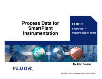
INTRODUCTION OF CONTROL AND INSTRUMENTATIONElements of a Control LoopProcess:The controlled system is called the process. It could be defined as a conditioned situationthat produces results which must be kept under an expected value or range of values. Asin Figure 2, the process deals directly with the product. Product in this case could betaken as a material, fluid, or whatever is produced, manufactured, or treated.Primary Sensor:The primary sensor is normally an instrument that has properties to detect the physicalproperty desired to be measured. An example is a thermocouple which produces a changein an electrical circuit proportional to the temperature; this signal is sent to a transducer tobe detected and interpreted.Transducer:The transducer is a device that translates the signal from the sensor into a processedelectric signal that can be amplified and used by the controller.Set Point:This is a fixed value that is contained in the controller, set by the operator or by anintelligent algorithm or device. This value is compared to the measured value from thetransducer. The difference of this comparison is called the Error.Controller:The controller is normally an electrical or electronic device that has the followingfunctions: Compares the sensing signal from the transducer to the Set point (at thesummation point) Produces an Error signal from the comparison Processes the error signal:o To convert it into an actuation signalo To manipulate it to condition it by an algorithm, this algorithm will makeit: proportional to the error as a function signal that anticipate changes as a function signal that uses history of changes to apply thecorrection as a function signal with a combination of the above features.Copyright 2010, Manuel GoodingPage 7 of 40
INTRODUCTION OF CONTROL AND INSTRUMENTATIONThe manipulation of the error signal is processed by a mathematical operator called acontrol algorithm. An example of an algorithm is the PID or Proportional, Integral,Derivative algorithm. This Algorithm uses: the mathematical constant K or proportional multiplier actuating the final controlelement in a linear way proportional to the value of the errorthe integral operator to produce an actuator signal based on the history of theprevious errorsthe derivative operator to produce an actuator signal anticipating the next changebased on the slope of the error functionOther algorithms are available easily today in the controllers; an example could be therate-lag operator which uses a combination of PID elements.Amplifier:The amplifier increases the intensity of the signal until it is large enough to be able to beused by the actuator.Actuator:It is an electromechanical device that takes the actuation signal and converts it intomotion following the actuation signal. This motion could be a position as in the case of asolenoid valve, on or off, or a motion, as in the positioning of a modulating or controlvalve.Final Control Element:It is the element upon which the actuator operates. This device is in contact with theprocess itself.An example would be a valve which closes or opens as operated by the actuator andcontrols in such a way the flow of a process, liquid, or gas.Copyright 2010, Manuel GoodingPage 8 of 40
INTRODUCTION OF CONTROL AND INSTRUMENTATIONPRIMARY SENSORSPrimary sensors detect the variable to be measured. The following sensing instrumentswill be presented in this portion of the course: PressureTemperatureLevelFlowInstrument CharacteristicsThe following table presents the most important general characteristics of instrumentsand their commonly accepted definitionsCharacteristicsStaticDynamicApplicable to variables that are not changingApply when variables are changingAccuracy:FidelityIs the instrument characteristic or capability tois the capability of the instrument to correctlypresent the real or actual measured variable?indicate or record a change in a measuredIf applied to a control system: it is thevariable?capability of the control system to maintain the For a control system, it is the ability of theactual measured value during the controlcontroller to follow the changes in the inputprocessvariable with the correct output signalStatic error:Dynamic error is the deviation of the controllerThe difference between the actual or true value output from its correct valueand the measured or indicated valueStatic error in a control system refers to thedeviation from the desired control valuecontributed by the control systemReproductivityResponsiveness The ability of the instrument to is characteristic of the instrument toproduce identical values of the samefollow variable changesmeasured variable when the measuredMeasuring lagvalue is the same under the same is the measured inability of theprevious conditionsinstrument to follow a variable change? A displacement from the same the measured duration of this lag isprevious value is called driftcalled dead timeCopyright 2010, Manuel GoodingPage 9 of 40
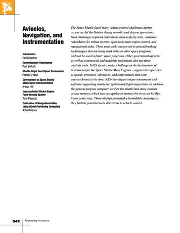
INTRODUCTION OF CONTROL AND vityis the magnitude of the smallest value that aninstrument can measure?Dead ZoneFor instrumentation, it is the range where theinstrument cannot measureFor control systems, it is the area of controlwhere the system cannot respondTable 2PRESSUREDefinitionPressure is a physical function of force and surface. The mathematical definition ofpressure is F/A where F is force and A is area.Mathematically:P FAForce is an action that causes distortion or movement.Surface is a section of the two-dimensional presentation of space.Other expressions of pressure:Hydraulic pressure in a press or tank: It can be expressed in water column height,mercury column height, psi, etc. This pressure is due to the weight of the mass of waterplus the weight of the mass of air on the water surface. It has been found that the pressureof a liquid can be expressed as a function of the height of the column of liquid.These expressions of pressure are based on experimental observations as well ascalculations and deductions using physical laws. The equivalence of these measurementscan be also be performed using dimensional analysis.To demonstrate the above concepts, we will use the case of the column of water pressuremeasurement.See Figure 3 for reference to the following calculations.Copyright 2010, Manuel GoodingPage 10 of 40
INTRODUCTION OF CONTROL AND INSTRUMENTATIONOne of the characteristics of matter is density. It is defined by the ratio between mass andvolume that it occupies. Water density has been given the value of 1.The relation that expresses density is:Mass 1 for waterVolumeFor specific density, we can replace mass by weight and the equation becomes:ρ sd Weight 1 for waterVolumeweight sd (Volume)FWeight sd (Volume) AAABut Volume Area times height orP sd ( Ah) (sd) h, since for water sd 1AP h for water.P The pressure exerted by the water column represented in Figure 3 is the height of thewater column (A to B). For another fluid, its P is AB times the fluid specific density.Figure 3– Pressure vesselCopyright 2010, Manuel GoodingPage 11 of 40
INTRODUCTION OF CONTROL AND INSTRUMENTATIONAtmospheric PressureThe column of atmospheric air has weight. Air applies pressure everywhere on earth thatis exposed to the atmosphere. Because pressure depends on the height of column of fluid,atmospheric pressure is smaller at higher altitudes. This property is the basis of earlieraltitude instruments. Also, water will boil using less heat at a higher altitude. Water willboil at a lower temperature in Mexico City than in New York City.To measure atmospheric pressure: Fill the bottom sealed tube with mercurySeal the other end of the tube with your fingerTurn the tube upside downSubmerge the end sealed with the finger inside a tank containing mercuryLet go of the finger as soon as the tube is vertical positionMeasure the height of the mercury column in inches, it is the atmosphericpressure given in inches pf mercuryGauge, Absolute and Differential PressurePressure can be expressed as gauge, differential and absolute pressure. Gauge pressureis the pressure that results of subtracting the atmospheric pressure from the pressure truevalue or Absolute Pressure. Absolute pressure is the true pressure measuring it inreference to zero pressure or vacuum. Differential pressure is the pressure of a systemcompared to the pressure of another system.Other pressure unitsPascal:The Pascal is the SI (The International System of Units, abbreviated SI from the FrenchLe Système International d'Unitéspressure measurement).The dimensional analyses is:FP AForce is given in newton and the area in square meter or a pascal is equal to 1 newtonforce per square meter area.Pascal is used in metrology expressed in a larger unit multiplied hundred times orhectopascal.1 hectopascal or hpa is equal to 100 pascal or 100 pa. As a physics reminder: 1 newton isthe force that accelerates the mass of one kilogram to one meter per second.When the height of the column of mercury is measured, the value is 29.9 in. at sea level.This pressure is indicated as 29.9 in of mercury.These units are equivalent to 14.7 psi or pounds per square inch 1 atmosphere (atm) 101.3 kPa (kilopascals) 14.7 psi (pounds per square inch) 760 torr.Copyright 2010, Manuel GoodingPage 12 of 40
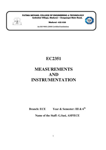
INTRODUCTION OF CONTROL AND INSTRUMENTATIONPressure SensorsInstrumentManometerDescription It is a U tube that contains aliquid. Levels at both sides areequal.One end of the tube is thenclosed; the other end is leftopen.The pressure to be measured isapplied to the open end.The level will rise on the closedend and it will sink in the openend.The pressure is given by thedifference in the levels.It is a mechanical instrumentthat senses pressure andconverts it to displacementThe pressure indication ismechanically amplified using apointer or indicator needleThe Bourdon-tube displacementis a function of the pressureappliedA set of two bourdon tubesmounted in one case is called aduplex gauge A bellows elastic element is aconvoluted unit It expands and contracts axiallywith changes in pressure.The pressure to be measured can beapplied to either the outside or the insideof the bellows Bourdon-tube Bellows ElasticElements - HelicalApplication Measurement ofpressure in liquid andgasesBlood pressuremeasurements.See Figure 4Many industrialapplications for fluidand gas pressuresHydraulic systems(hydraulic gauges)Low-pressureBourdon tubes(pressures up to 2000psi) are often made ofbronze.High-pressureBourdon tubes(pressures above 2000psi) are made ofstainless steel or otherhigh-strengthmaterialsUsed mostly forhydraulic fluidmeasurements.See Figure 5 - Bourdon TubeManometer and Figure 6 Helical Bourdon PressureInstrument for its componentsCopyright 2010, Manuel GoodingPage 13 of 40
INTRODUCTION OF CONTROL AND INSTRUMENTATIONInstrumentSimple BellowsElementPressure SwitchesDescriptionApplicationBellows elastic elements aremade of brass, bronze, stainlesssteel, beryllium-copper, or othermetal Motion of the element (bellows)is transmitted by suitablelinkage and gears to a dialpointer. Most bellows gauges are springloaded with a spring thatopposes the bellows force andprevents full expansion of thebellows.To determine specific pressures, such asa high or low pressure, pressureswitches are used to activate a signalthat is sent to the monitoring and alarmsystems.The principle used in thisinstrument can be used also tomeasure differential pressure.In this case, there are twobellows chambers withmechanisms that subtract thetwo pressure producedmovements. Single pole single throwswitches are frequently usedfor these applications.Electronic switches are alsoused in newer devices. SeeFigure 8.Table 3Pressure Instrument CalibrationThe calibration of a pressure instrument has been traditionally done using a methodcalled the dead weight calibration.A typical test set-up is shown in Figure 9.The setup works ion the following manner:Step1234ProcedureLoad the measuring piston with calibrated weightsAdd or retrieve load until the loaded measuring piston rises and appears to floaton the fluidCalculate the pressure using the formula P FAUse the weights as the force and the area of the piston as the ATable 4Copyright 2010, Manuel GoodingPage 14 of 40
INTRODUCTION OF CONTROL AND INSTRUMENTATIONPressure Instruments FiguresFigure 4 – U-Tube ManometerFigure 5 - Bourdon Tube ManometerCopyright 2010, Manuel GoodingPage 15 of 40
INTRODUCTION OF CONTROL AND INSTRUMENTATIONFigure 6 - Helical Bourdon Pressure InstrumentFigure 7 – Simple Bellows GaugeCopyright 2010, Manuel GoodingPage 16 of 40
INTRODUCTION OF CONTROL AND INSTRUMENTATIONCopyright 2010, Manuel GoodingPage 17 of 40
INTRODUCTION OF CONTROL AND INSTRUMENTATIONTemperatureThis section will present the basic concepts of temperature, its measurements, andtechniques. Definitions and a small section of the physics of temperature will begin thesection; later a presentation of the most commonly used temperature sensors andtransducers will be outlined including reference material for practical engineering use.DefinitionsTemperature is defined as the degree of heat or cold that an element exhibits. Thisconcept comes from practical evaluation of the thermal behavior of substances, mostcommonly water.A more sophisticated definition would be: the measurement of temperature is themeasurement of the average thermal energy per molecule contained in a material.The unit used to describe the thermal energy per molecule of a certain material is thedegree of temperature. These units are arranged in a scale called the temperature scales.An important place to calibrate a temperature scale is a point of equilibrium thermalequilibrium in the substance. This point is seen as a temperature in which the substanceremains at an equilibrium, (ie. ice and water mixture or water an steam).In water, there are several points of thermal equilibrium at a given pressure.The most notable point for water is the point in which solid, liquid, and gas are atequilibrium (triple point). This point exits at normal atmospheric pressure of oneatmosphere and it is the zero-degree point for the Celsius thermal scale.Another point of the scale calibration could be found at the point where liquid and gaswater are at equilibrium at one atmosphere. This point was arbitrarily given the value of100 on the Celsius scale. Then the scale was built dividing it into 100 equal divisions.Other scales use other equilibrium points; the Fahrenheit scale uses a zero point as thepoint where a mixture of salt (NaCl) and water allows the existence of liquid and solidwater to remain at equilibrium.The relations shown below can help to convert Celsius to Fahrenheit and Fahrenheit toCelsius5C (F-32)99F C 325Copyright 2010, Manuel GoodingPage 18 of 40
INTRODUCTION OF CONTROL AND INSTRUMENTATIONTemperature SensorsTemperature is measured using the fact that when exposed to temperature changes, somematerials change. Some changes are changes in physical properties and physicaldimensions.There many types of change that are related to thermal variations such as: LengthElectrical propertiesEnergyLengthSome metals change in length of as well as expand and contract when subjected totemperature changes. These changes are used to design temperature sensors.ElectricalGenerationWhen temperature changes are applied to two different materials in physical contact,there is a migration of electrons from one of the materials to the other due to thedifference of each material’s electrochemical properties. This effect is used inthermocouples.ResistanceBecause resistance is a thermal property of materials (discovered by Joule), it would beexpected that a change in temperature would produce a change in resistance; this is usedby RTDs.EnergyInfraredInfrared temperature measurement is used to measure temperature in radiating bodies andat a distance. Such measurement could be the temperature of an oven or the temperatureof a remote hot object. The explanation of this method of temperature measurement usesquantum mechanics starting with Plank’s radiation law.Temperature Sensors – Length BasedThe most commonly used sensor based on length changes is the bimetallic sensor. Itsimportance is due to its practical use and price. Bimetallic sensors are used in manyelectrical applications, including motor overload trip devices and temperature measuringindicators.Copyright 2010, Manuel GoodingPage 19 of 40
INTRODUCTION OF CONTROL AND INSTRUMENTATIONA metal exposed to heat will expand or contract with heat. The length that a metal willexpand at given temperature is different for each metal.When two strips of different metals are joined together at both ends they will bend as thetemperature is increased. One metal will expand more than the other, forcing the pair tobend. The distortion depends on the amount of temperature surrounding the metals.This property can be used to create a thermometer as shown in Figure 10.The instrument shown in Figure 10 is made with a spiral wound bimetallic wire. As thewire gets hot the wire size increases and bends due to the constraint of one metal by theother.Copyright 2010, Manuel GoodingPage 20 of 40
INTRODUCTION OF CONTROL AND INSTRUMENTATIONElectrical Based Temperature SensorsThermocouplesGeneration of electricity is a phenomenon that occurs when two dissimilar metals arejoined together. Each metal has a different level of energy due to its electronic level. Thisis referred sometimes as the energy well of the metal.When two different metals are joined together with a small separation between them,there is a thermos-ionic migration from the metal that has the smallest energy level.This effect is called the tunnel effect and occurs for very small distances, small enough toallow the electronic energy level of each metal superimpose each other.A distance of 10-7 centimeters would allow this effect to happen. A detailed explanationof this effect is beyond the intent of this course.The previously described effect is called thermocouple effect. The increase intemperature will increase the amount of energy in the junction and more current will flowfrom one metal to the other.Resistance Temperature Detectors or RTDResistance is always part of a conductor. Heat generated by a conductor by the flow ofelectrical current is intimately related to resistance. The temperature of a conductor willalter the value of the resistance of the conductor. An RTD is a device that detectstemperature based on this property.Normally a RTD is made with of a fine coil of metal wrapped around a ceramic or glasscore. To protect this delicate arrangement, it is placed inside a sturdy probe.The resistance of the metal used in the RTD is well documented at various temperatures,via testing of the RTD response to various temperatures. Many selected materials havewell established and documented change in resistance as the temperature changes.To measure the temperature using an RTD, use RTD reference tables which are based onspecific values of the RTD resistance versus temperature.RTDs are used when the following important factors are required: AccuracyStabilityRepeatabilityImmunity to electrical noiseAdditionally, the time response of RTDs is better than other similar thermal instrumentsused in the same applications, such as thermocouples.Copyright 2010, Manuel GoodingPage 21 of 40
INTRODUCTION OF CONTROL AND INSTRUMENTATIONBoth thermocouples and RTDs are placed in thermowells when the temperature is to besensed inside a tank or a pipe. See Figure 11 –Thermowell.Figure 11 –ThermowellEnergy Based SensorsInfrared detection is produced detecting light in the infrared frequency emitted bymaterials. The detectors use materials that will react to the energy content of infraredwaves and their reaction can be quantified and translated into temperatures. In quantumtheory, using the Stefan-Boltzmann Law, we can say that the total radiation energy(emitted by the material) is proportional to the fourth power of the absolute temperature.The early twentieth century scientist Wien indicated in his “Displacement Law” that theproduct of the peak wavelength and the temperature is a numerical constant. He wasawarded the Nobel Prize for Physics for the year 1911.This relationship can be used to measure temperatures.The sensor in an IR (Infra-Red) thermometer collects a small amount of energy (usually0.0001 watt) radiated from the target, then it generates an electrical signal that isamplified by a sensitive amplifier and converted into voltage output.An analog to digital chip (such as a 16 bit Analog-to-Digital Converter) digitizes thesignal sending the signal to an Arithmetic Unit which solves a temperature equationbased on Planck’s Radiation Law; it uses an algorithm to compensate for the ambienttemperature and emissivity. The result of these manipulations produces a temperaturereading.Copyright 2010, Manuel GoodingPage 22 of 40
INTRODUCTION OF CONTROL AND INSTRUMENTATIONLEVELLevel SensorsLevel measurements are an essential part of modern industry. Tanks containing fluids andsolids have their levels continuously monitored to determine the amount of material, toprevent spills or overflow, and to determine the need to add more material.One way to classify level sensors is by how the measurement is made, either directly orindirectly, depending on the material that is being monitored.Direct methods are used to measure liquid levels, granular material such as grains, andpowder, or flour and salts.Indirect methods use other physical properties to indirectly determine the level ofmaterials. Among these physical properties are: pressure which could vary with theincrease or decrease of material in a container, or weight inside the container.Another way to classify these instruments is how the sensor senses the material. In thiscase, the detection could be either continuous detection or a single point detection. Thecontinuous detection sensors detect the level as it changes. This detection method sensesthe level at a certain specific point. One example would be a low-level point; anotherpoint would be a high-level point. This type of sensor is normally a switch or switcheslocated to be activated as the corresponding level is reached.The following table will present the most common level sensors.Level sensorsSensorFloatsPneumaticConductivity probesType/DescriptionThis type of sensor is a direct measurement and point detection sensor.Traditionally it has been a floating ball connected to the controller bymeans of a rod or link, the movement of the ball positions a linkedlever that actuates the corresponding switch.More modern units use a floating cylinder containing a ferromagneticmaterial. See Figure 12. This cylinder slides on a shaft that contains amagnetic link or rod. The link or rod moves as the level varies, theposition of a cam on the other end of the link or rod actuates switchesmounted in the switching housing.This type of sensor is a direct measurement as well as point detectionsensor.Pneumatic level sensors are used in hazardous areas, such as thoseclassified as IE by the NEC, or where there is no electric power, and inapplications involving material such as sludge.The mechanism of these devices is as follows:When the level of the material changes, it compresses a column of airwhich is in contact with a diaphragm. This diaphragm actuates aswitch, which
The control loop configuration should be open, as in the control of a valve to open. The controller receives the signal to open the valve. That operation is completed without additional action. The loop is open because it starts at the open command and ends at the valve opening. This is known as an open-ended control.