Transcription
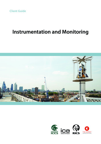
Client GuideInstrumentation and Monitoring
Client Guide to Instrumentation and MonitoringDefinition of termsActivityThe construction, development or aggravating operation.AssetThe item or feature to be measured, such as a wall, bridge, railway or building.Global Navigation Satellite Systems (GNSS)GNSS is the overall term for positioning satellite systems such as GPS, GLONASS, Galileo and BeiDou.Impact assessment (IA)A report that covers geotechnical analysis and live and dead loading effects. It covers the existing capacity arrangementsand how they affect structures. Predicted movements are quantified to help define associated trigger and action levels. Thereport will commonly be referred to as a ‘structural IA’ or ‘settlement IA’.Instrument and monitoring (I&M)I&M is a commonly used abbreviation for the particular instruments and monitoring systems to be used.Instrument and monitoring plan (I&M plan)A report produced for the client by the designers involving the structural assessment team, geotechnical and I&M specialistscovering the recommended instruments and monitoring methods to be used.MovementThis can refer to x, y, z, angle, rotation heave, settlement and displacement.Zone of influence (ZOI)The identified area that will be affected by the activity. Specialist structural engineers and geologists would need to beconsulted to determine the ZOI.References and sources of informationMeasured surveys of land, buildings and utilities: Client requirements guidance note and specificationRICS 3rd Edition, ISBN 0 85406 539 3Geotechnical investigation and testing: Geotechnical monitoring by field instrumentationGeneral rulesISO 18674-1: 2015Geotechnical investigation and testing: Geotechnical monitoring by field instrumentationPart 2: Measurement of displacements along a line: ExtensometersISO 18674-2: 2016Geotechnical investigation and testing: Geotechnical monitoring by field instrumentationPart 3: Measurement of displacements across a line: InclinometersISO 18674-3: 20172v1.0
Client Guide to Instrumentation and MonitoringContentsDefinition of terms 2References and sources of information 21.Preface 42.Introduction 43.Terms of reference 44.Purpose 55.Scope of monitoring 66.Information required to establish an initial assessment6.1Identifying the asset 76.2What type of movement are you interested in?7.Commencement and lifespan 97.1Influences on the asset to be considered97.2Why is the asset being monitored?97.3What elements of the asset should be measured?98.Requirement of the scheme 108.1Duration 108.2Frequency 108.3Units and type of change to be measured8.4Reporting interval 118.5Triggers, alerts and limits of predicted or acceptable movement9.Data management system 129.1Objective 129.2Key requirements 1210.Operational phasing 1310.1Selection of monitoring system and method10.2Installation 1310.3Commissioning 1310.4Baseline data 1310.5Reporting 1310.6Maintenance and service interventions 1410.7Decommissioning and reinstatement 1410.8Archiving 1411.Equipment and accuracies 1511.1How do we monitor? 1511.2System accuracies 1511.3What errors could occur in a monitoring system?7810111315Appendix A: Accuracy bands 16Appendix B: Operational phasing process 17Appendix C: Geotechnical monitoring system design18Appendix D: Geospatial/geodetic monitoring equipment19Appendix E: Geotechnical monitoring equipment 22Appendix F: Example trigger level and actions - flow diagramv1.0273
Client Guide to Instrumentation and Monitoring1. PrefaceThis first edition of the Client Guide to Instrumentation and Monitoring has been prepared to assist those associated with theinception, design, management and undertaking of monitoring projects. It has been compiled by public and private industryexperts along with instrument and software manufacturers.The aim of the guide is to consider the common questions posed by clients, designers and contractors during a monitoringscheme – from the initial inception through to installation. As with all projects, it is important that a solution is right first time;is cost-effective; sets out to achieve objectives; and adds value to a project.In a fast-moving world, technological enhancements and innovations offer various solutions for monitoring, but whatremains paramount is the fundamental understanding of what you are monitoring and why. Various questions will be posedwithin this guide that provoke thought, debate and solutions, as well as raising an industry awareness of the equipment andmonitoring systems on offer.It is hoped that this best practice reference guide will contribute to transparency as well as enhanced collaboration betweenall parties involved on a project. Individual professionals shall have the responsibility of deciding upon the appropriate finalchoices and criteria to meet project requirements.The following have contributed to this document;Mike Brown (Network Rail), Sean Brown (Skanska), Marco DiMauro (Leica Geosystems), Stuart Edwards (Newcastle University),Nick Giles (Morgan Sindall), Aidan Laimbeer (Senceive), Mark Lawton (Skanska), Angus Maxwell (Maxwell Geosystems),Chris Preston (Network Rail), Graham Smith (Senceive) and Steven Thurgood (SCCS).Thanks are expressed to the equipment suppliers, manufacturers and monitoring companies for supplying imagesand equipment data information; Trimble, Leica Geosystems, Topcon, RST Instruments, Imetrum, Telespazio, Gete andGeotechnical Observations.2. IntroductionThis document is a guide for clients to select the most appropriate monitoring scheme and allows them to formulateboth general and specific project requirements. This initial information will then allow a monitoring specialist to propose,design and implement an optimum solution with the advantage of being aware of the technical systems as well as advancesin technology.It will be important that the project team understands the scale of movement predicted (usually through an impactassessment, including the zone of influence) and the size of movements to be detected. An understanding of the capabilityand capacity of an asset is required to determine if any movement is likely to cause a detrimental effect that couldinterrupt operations.3. Terms of referenceMonitoring can take many forms; environmental, geospatial or geophysical. All are important in gaining a full understandingof the factors at play in a given location. The focus of this document will be geospatial monitoring, concentrating onsettlement monitoring and the movement of assets.4v1.0
Client Guide to Instrumentation and Monitoring4. PurposeWhy do we monitor?Protecting our national heritage is of paramount importance, especially the history that it represents. The regeneration andrestoration of assets using innovative and challenging design and build processes needs different solutions as technologyand techniques advance. Linked to this is protecting the assets we already have, such as listed and heritage buildings. Anynew works must not have a detrimental effect on their structural integrity.It will be important to observe movements that the client and designers deem to be of critical importance. This can becontrolled by a previously known asset identification list and the operational working tolerances that apply. Escalators andrailway tracks are examples of operational assets that would have key safety movement band tolerances pre-identified.Providing accurate and precise monitoring systems that deliver data representation, analysis and interpretation of resultsis important so that we can understand the relationship between construction activities and any potential deformationmovement. The information collected allows: Lifecycle planning and preventative maintenance of an asset. Movement trend analysis to confirm behaviour and design model predictions. Recording for the operations manual and project archive purposes. Statutory duties to be performed. Preparation of safety cases. Safeguarding of existing buildings and other adjacent facilities. Assurance to relevant stakeholders. Value for money while delivering added value.v1.05
Client Guide to Instrumentation and Monitoring5. Scope of monitoringWhen considering the scope of monitoring, the client and monitoring specialist should ask: What are the site extents and the zone of influence (ZOI)? What accuracy is required and at what intervals or frequency are measurements and readings required? What is the rate of predicted change and movement? What is the expected duration of the monitoring activity? How long does the baseline monitoring period need to be before activities start? Is there a monitoring and risk mitigation plan for during and after activities? Is there a long term monitoring plan accounting for residual movement? What measurement techniques and equipment will be used? Is there an absolute or relative monitoring requirement? What software and data formats will be used? What kind of interface will display the report? Will it need to be available on a web portal? What are the trigger thresholds? Keep in mind that a factor of safety may be required to protect against instrument error. What reporting systems and actions need to be in place?SafetyConsider risk reduction for any unplanned additional time for delays; increased costs mitigation/avoidance; and health andsafety guidance to the workforce and public.Risk planningAllow for risk management and forward planning to mitigate delays and avoid increased costs. Consider what liabilities couldor would be associated with the works and any potential movement detected.Asset managementReview the asset in relation to its long term structural health monitoring, beyond any associated works deemed to haveany movement influence. This could be in relation to the design life of an asset which is extended; long term environmentaleffects which may increase fatigue in a structure, such as a bridge, or safety critical assets, such as a steep railwayembankment or cutting, which could have a greater risk of failure.6v1.0
Client Guide to Instrumentation and Monitoring6. Information required to establish an initial assessment6.1 Identifying the assetLocationThe asset location should be provided in a detailed description using aligned referencing consistent with the asset owner’snumbering or reference system. Plans, photographs and maps are key to identifying the asset location in relation to itsenvironment and physicality.The asset and its conditionA detailed description of the asset type should be provided that is sufficient enough to identify what features requiremonitoring along with their current condition.Note: The accuracy band table in Appendix A (Table 5) should be reviewed before completing Table 1. Further consultationwith other experts to attain anticipated movements of geological features and structures should be undertaken.AssetRequiredAccuracy mbankments)Walls(inc retaining walls)RailwaysRoads and highwaysBridgesTunnels and subwaysUnderground utilitiesand servicesDams and embankmentsCoastal erosion andbeachesArchaeology abstractsOther (specify)Table 1: Assets to be monitored.Interested partiesAll interested parties and stakeholders should be described, be they the immediate asset owner, companies/persons involvedwith works or changes to the asset or a third party.v1.07
Client Guide to Instrumentation and Monitoring6.2 What type of movement are you interested in?The interested party should provide a brief outline of the type of movement expected. For example, vertical movement,horizontal movement or a combination of both; or movement parallel or perpendicular to site gridlines or in relation to aparticular asset or structure, such as a railway line, retaining wall or river. This aids the interpolation of the data.Furthermore, for data analysis purposes, it is common practice to quantify these movements as displacements, be theylongitudinal (perpendicular), lateral/transversal (parallel) or, in the case of tunnel monitoring, described as sectional change.Movement typeRequiredCompliant equipmentHorizontalExtensometers; global navigationsatellite systems (GNSS);interconnected tilt sensors; shapeaccel arrays (SAA); tape measures(offset markers); terrestrial laserscanners; total stations (manual rs; global navigationsatellite systems (GNSS);interconnected tilt sensors;interferometry; laser alignmentsystems; precise levels; shape accelarrays (SAA); total stationsRotational(about the Z axis/twist)Accelerometers; gyroscopic devices;photogrammetry (camera andimage-based); total stations; videomonitoringTilt (about the X or Y axis/inclination)Inclinometers; plumb lines;tiltmetersVibrationAccelerometers; geophones;velocimetersCrack/joint expansionCalibrated digital images;crackmeters; digital calipers; laserscanners (manual and automated);non-invasive systems; tell-tales;total stationsStrainCalibrated digital images; fiberoptics; potentiometer; strain gaugesConvergenceShape accel arrays (SAA); tapeextensometers; tilt sensorsCombination of any ofthe above to providevalidationCalibrated digital imagesOther (specify)Environmental monitors; noiseand vibration monitors; weatherstationsCommentsTable 2: Movement type and compliant equipment.8v1.0
Client Guide to Instrumentation and Monitoring7. Commencement and lifespan7.1 Influences on the asset to be consideredUnmanageable influencesWeather factors, such as rain, wind, temperature and sun, will affect the movement of the asset. Movement can also comefrom other external factors, such as tidal river loads, the ground water table and peak hour traffic. The combination of thesecan be termed seasonal effects and/or environmental trends for which the implicated baseline monitoring period shouldbe undertaken over a sufficient time period to establish background information. Evaluation of this information will aidunderstanding of movement trends over time. ‘Acts of God’, such as natural disasters (flooding, storms, droughts, tectonicactivity and so on), may have significant effects on any system – both in displacement and function. These normally cannotbe accounted for in the predictions, however, a pre and post-event analysis could be undertaken to quantify their effect.Manageable influencesPassive and dynamic loads could affect the asset. A passive (dead) load such as a stockpile adjacent to another part of the asset could cause influence. A dynamic (live) load such as differing amounts of traffic on a bridge at different times of the day or days of the weekwould cause a dynamic influence.Development and construction activitiesConstruction, refurbishment or demolition of another asset or buildings within the zone of influence can affect movement.This needs to be considered relative to the project lifecycle, designs for works and the monitoring specification.Change to existing conditionsWhen the use of an asset or an adjacent asset alters, this can have an influence on the asset’s movements and needs to beconsidered and accounted for. For example, this could be moving road or rail traffic on another part of a bridge, the closureor opening of an office floor, or the removal of bridge structural components for refurbishment.7.2 Why is the asset being monitored?Various scenarios may be considered in answer to this question. However, some possible explanations are: Is the asset identified as being ‘safety critical’ and being monitored to ensure it is not operationally affected during theactivity period? (An example of this would be railway track movements and clearances). Is the change to the asset affecting a third-party asset in the activity period? (This could be related to managing risksassociated with the asset or a third-party asset that are covered by an insurance policy. By installing a monitoring system,it may allow the negotiation of better insurance premiums for risk liabilities.) Is it to provide assurance and confirm movements do not exceed predictions? Is it to give confidence that the asset is complete during and after adverse weather? Is it to keep an infrastructure route open? Is it to understand the rate of change of an asset?Note: Where a new third-party asset is identified, it is necessary to re-appraise the asset from the beginning again.7.3 What elements of the asset should be measured?Specific points of interestAny critical points or points of interest should be identified so that the designs for monitoring schemes incorporate these.Size of the assetTo ensure the extent of the asset is fully identified, the original foundation design drawings should be reviewed.Amount of change in the assetIs the measurement area going to be the same at the beginning through to the end? Demolition, refurbishment andconstruction nearby can remove or introduce new areas where the asset will have a requirement to be monitored. How willphases of works affect the asset as they progress? Will any monitoring be viable for the lifecycle of the project?Zone of influence or item to be monitoredThe zone of influence (ZOI) and features to be monitored should be identified clearly before planning any scheme. It is criticalto identify any overlapping ZOI or monitored items. In addition, an impact assessment report may identify ‘hot-spots’ within aZOI, for which the largest movements are predicted. In these situations, there may be opportunities to maximise operationalefficiency and design the instrumentation and monitoring (I&M) plan so that the proposed monitoring focuses on these keyareas in a different way. The continuous review of the collected monitoring data may enable analysis of actual data versusthe predicted data, and so change the ZOI as the activity progresses. This enables a lean and proactive scheme relative to theongoing activity. This may increase or decrease the requirements in particular areas with the agreement of the client, assetowners or third party.v1.09
Client Guide to Instrumentation and Monitoring8. Requirements of the scheme8.1 DurationThe duration of the scheme must be linked to the proposed activity. Consider whether unmanageable and manageableinfluences are going to be contributory factors to the duration. Pre and post-activity monitoring should be considered,and allow for the design, procurement, installation, commissioning and decommissioning of the monitoring scheme. Theduration may be impacted by the scheme design and whether it is automated or manually measured and processed.8.2 FrequencyThe frequency of measurement must be directly linked to the works activity or expected rate of change of geotechnicalmovement. Measurements should be at the highest frequency for the baseline readings or when the likely influence from theactivity is at its greatest. The frequency rates are subject to change due to actual and anticipated movement rates. The rate ofpredicted change may also govern the monitoring data collection method between real-time automated and manual.Table 3 concerns typical frequency requirements.FrequencyRelevant onthlyQuarterly/seasonallyAnnuallyOther (specify)Table 3: Monitoring frequency.8.3 Units and type of change to be measuredThe units of measurement and their display should be identified to assist in interpreting the data (such as millimetre, angle, acombination of millimetre per metre, or even unitless like microstrain).Note: Movement parallel or perpendicular to a particular asset such as a railway line or river aids with interpolation ofresultant data.Relative changeRelative change is change to an object or to assets relative to each other within the zone of influence (ZOI). Measurablepoints can be established on the structures in question but do not necessarily have to be referenced to stable monumentsoutside the ZOI (although this may be helpful in background corroboration that genuine and real movement has happenedat a point in time within the ZOI). Relative movement is then reported. (An example of this would be the amount of sag of asteel beam from its initially monitored position.)Absolute changeThe absolute position requires geospatially referenced x, y, z, θ, ψ, φ (east, north, height, yaw, pitch, roll) values related to adefined grid and/or height datum. In these situations, stable permanent ground markers (PGM) may be established or keyedinto solid rock so that they are independent of any on-site structural movement within the ZOI. Alternatively, a fixed referenceframe outside the ZOI that could be used to determine change would be of use. (For example, GNSS-based for coordinates,10v1.0
Client Guide to Instrumentation and Monitoringparticulate PPM calibrated sensors for environmental, or beam calculations where both ends are out of the ZOI.)There should be sufficient quantity to allow determination of whether the reference frame or the asset is changing. Such adataset may also be used for other tasks across the duration of the project and after.Note: Coordinate-based monitoring system surveys should be connected to a local project grid, such as Snakegrid or anational grid system. (For example, the squat in a tunnel that requires the true position to compare with the activities orassets above ground and relates to an off-site fixed datum.)Geospatial monitoring data will be collected in a homogeneous coordinate system to facilitate the comparison of resultsand to provide a dataset that can be used for different tasks across the duration of the project and after. This will ensurethe possibility of comparing results and set alarms and alerts on multiple sensor results to provide redundancy and themaximum level of reliability.8.4 Reporting intervalThe reporting interval may differ from the measurement frequency and can be at such an interval as to ensure that anytrends are identified, rather than individual data spikes (outliers) causing immediate alarms. For example, reporting changemay be required every 24 hours yet the measurement frequency may be every four hours to measure more than theminimum required data. However, in different phases of the activity, the measurement frequency may change relative to therisk or likelihood of movement due to different activities on the asset. These should be planned at the scheme design stage.8.5 Triggers, alerts and limits of predicted or acceptable movementIt is imperative to understand the limits of movement of each asset. The client should ensure that its specialist consultantsand design team advise on the predicted and acceptable movement of each individual asset.The designer, contractor and monitoring specialist should prepare action plans and/or emergency preparedness plans (EPP)in association with the impact assessment and baseline monitoring data. These shall be produced for each asset owner orstakeholder (such as Network Rail, Transport for London, utility company or building owner). The designer will specify thetrigger values for each movement type and the actions that will be undertaken in the event of a breach being triggered.These will be agreed with any affected stakeholder. An example trigger level and action flow diagram is provided inAppendix F.v1.011
Client Guide to Instrumentation and Monitoring9. Data management system9.1 ObjectiveThe data management system may be required to have capabilities to include data from geospatial (such as total stationsand precise levels), geotechnical (such as piezometers, extensometers and earth pressure cells), environmental (such as air,dust, noise and vibration monitors) and construction instruments and sensors (such as tunnel boring machines, graders androadheader drills) within one platform. It should also include progress and commentary on works activities. The platformshould allow the user to track cause, effect and magnitude.It may also require information about the surroundings (such as factual details for hazards, sensitive structures, borings,samples and tests). Predictions from ground modelling or calculations to allow movements to be compared withexpectations may also be needed.The system should reduce the time spent on data processing following data collection and increase the time spent on dataanalysis.9.2 Key requirementsThe identified data management system may be required to have the following capabilities: Fully web-based using technologies with proven future proofing. Dedicated database storage servers (local project based and web-based via FTP). Flexible data transfer options via LAN, FTP and Wi-Fi. Accessible over all devices on 3G or better connections. Secure and allow local mirroring to reduce reliance on web connection and back-up of data. Designed and proven for the data volumes required and Internet speeds envisaged. Accept raw data and independently process data to provide complete data transparency. Interoperable: Accept data from a variety of data sources and formats covering the majority of all instrument,construction, investigation and design output types. Store original files provided and track all changes to data values and settings and reasons for changes. Allow configuration by the end user, without reliance on the system supplier for any data type, configuration, calibration,calculation, graph or report. Allow distributed pre-processing, if required, to handle high volume data. Have built-in audit, quality control and filter functions to ensure high quality of data release to the wider project. Flexible and efficient alarm notification and close-out system. Hierarchy of permissions to control access to and security of data. Map-based with viewing of data in a variety of coordinate systems, such as Snakegrid, local or chainage, level and so on. Configurable graph and map plotting and reporting, allowing multiple types of data to be combined in one display. Allow ready communication (data extraction from databases) with other software in use on the project, suchas programming, building information modelling (BIM), geographical information systems (GIS) and documentmanagement, using custom queries and API. Automation of common tasks and general reporting. Metadata functionality with the collection and recording of information, such as construction history events andphotographs tagged to monitoring data.12v1.0
Client Guide to Instrumentation and Monitoring10. Operational phasingThe operational phasing of a monitoring scheme follows key steps. These are related to the asset and activities. They shouldbe acknowledged and addressed before procurement and used as stage gate testing points to ensure the relevance of themonitoring to the activity on the asset. Appendix B gives an operation phasing process flow diagram and Appendix C detailsa typical geotechnical and monitoring system design process.10.1 Selection of monitoring system and methodSelection of a system and method will be based on the previously identified parameters relative to the requirements. It mayinclude creation of an impact assessment plan, design mitigation review and assessment, monitoring plan and supportingdocumentation, such as method statements and qualitative load assessment of fixtures and fittings.10.2 InstallationAll affected parties shall agree the installation or at least have an approval in principle in place. Practicality of the installationand any lifecycle operation or maintenance should be considered during the planning. Planning can take significantly longerthan actual installation time – sometimes in the region of 75% planning, to 25% installation – and would be linked to thecomplexity of the asset and conformance to client standards. Restrictions and constraints regarding access to assets must benoted, such as railways and highways, during the installation stage and beyond into operation and decommissioning.10.3 CommissioningCommissioning requires a quality control process specific to each scheme. Commissioning should include the capture,initialisation and visualisation of data within the report reviewer’s deliverable, and any other subsequent databases anddatasets.10.4 Baseline dataThe scope and requirement for baseline data capture shall be related specifically to the activity and the specific asset orelement within the asset and not copied generically from another scheme.10.5 ReportingReporting of monitoring movements should alert the authorised people in a comprehensive manner providing specificinformation in relation to the construction timeline and activities. However, a manual check of alert triggers is a wiseprecaution to avoid unnecessary alerts being sent to authorised people. Typical outputs of a monitoring project are identifiedin Table 4. Note: Deliverable format types would range from spreadsheets, graphical representations, database, reports(Word, pdf and so on), image files, CAD model files or any combination of these.OutputRequiredDigital deliverableformat (if required)CommentsSupply of monitoring systemPlan of monitoring pointsSurvey report detailing methodologyBaseline data and historicalbackground movement analysisSurvey report detailing monitoringpoint movementTabular/graphical survey resultsWebsite based resultsCritical tolerance alerts via email/SMStext messageInstallation, decommission andclose-out reportsOther (specify)v1.0Table 4: Possible monitoring outputs.13
Client Guide to Instrumentation and Monitoring10.6 Maintenance and service interventionsMonitoring equipment will require periodic calibration, maintenance and visits for potential unforeseen equipment failure.Accessibility restrictions should be reviewed and if possible mitigated during the initial planning, design and installationstage within a
Client Guide to Instrumentation and Monitoring 1. Preface This first edition of the Client Guide to Instrumentation and Monitoring has been prepared to assist those associated with the inception, design
