Transcription
Unit 12, Owenacurra Business Park, Midleton, Co. CorkT 353 21 4631600 F 353 21 4638690 E geotechnical@priority.ieENNISCORTHY FLOOD DEFENCE SCHEMEGROUND INVESTIGATION CONTRACTINTERPRETATIVE REPORTNO. P16087Client:Wexford County CouncilEngineer:Mott MacDonald ConsultingEngineers,County Hall,5 Eastgate Avenue,Carricklawn,Eastgate,Wexford,Little Island,Co. Wexford.Co. Cork.21/12/2017
REPORT CONTROL SHEETEmployerWexford County CouncilEmployer’sRepresentativeMott MacDonald Consulting EngineersEnniscorthy Flood Defence Scheme – Ground Investigation ContractProject NameReport NameEnniscorthy Flood Defence Scheme – Ground Investigation Contract –Interpretative ReportProject NumberP16087This ReportComprises ofRCSTOCTextNo. sionStatusAuthor(s)Approved ByIssue DateD01DraftGHNL19.04.2017F01Final21.12.2017
TABLE OF CONTENTS12INTRODUCTION . 11.1SCOPE OF WORKS. 11.2REPORTING . 21.3SITE LOCATION & DESCRIPTION1.4PUBLISHED GEOLOGY . 5. 4FIELDWORK. 22.1GENERAL. 22.2EXPLORATORY HOLES . 32.3SAMPLING . 62.4GROUNDWATER MONITORING . 62.5IN SITU TESTING . 103LABORATORY TESTING . 124GROUND CONDITIONS . 145GROUNDWATER CONDITIONS . 156GEOTECHNICAL REVIEW . 216.1GROUND MODEL(S) AND CHARACTERISTIC PROPERTIES . 256.1.1Right bank (SKA01 – TPA01) ch6 900m to ch6 500m . 256.1.2Left bank (TPA02 – TP35) ch6 500 to ch5 750 . 306.1.3Deposition area DA1 (TPA03 – TPA05) ch6 700m . 356.1.4Deposition area DA2 (TPA08 – TP035) ch6 000m . 376.1.5Railway line (BH301 – BH307) ch0 100m to ch0 500m . 396.1.6Railway Bridge (RCP1, RCP3, RCP5 and RCP06) ch5 690m . 466.1.7Right Bank (BH018 – BH027) ch6 100m to ch5 690m . 486.1.8Left Bank (TP001- BH003) . 606.1.9Left Bank (BH006 – BH010) ch5 690m to 5 535m . 636.1.10Left Bank (BH011 – BH072) ch5 535m to ch4 900m . 736.1.11Right Bank (RC030 – BH101) ch5 690m to ch4 900m . 866.1.12New bridge structure B05; RC201 – BH109, ch4 700m . 986.1.13Flow control structures C01; BH001/ BH002 ch0 700m and C02; BH004/ BH005ch0 150m . 1176.1.14Enniscorthy Bridge, B02; RC401 to RC404 ch5 535m . 1276.1.15Channel realignment ch4 800 to ch3 600/ Deposition area DA3, ch4 400m toch4 000m,realignment EX8 and embankment works . 1326.1.16Channel dredging . 1386.1.17Miscellaneous ground hazards . 1406.2GROUNDWATER . 1426.2.1Made ground . 142P16087 RP INT F01i21/12/2017
6.2.2PEAT . 1426.2.3Peaty SILT . 1426.2.4Sandy SILT . 1426.2.5Silty sandy GRAVEL . 1436.2.6Sand . 1436.2.7DOLERITE . 1436.3FOUNDATIONS . 1446.4CHEMICAL . 1446.4.1Pyrite . 1456.4.2Contamination . 1456.5RE-USE OF MATERIALS. 1476.5.1Cutting EX1/ EX2, right bank ch6 500m to ch6 780m . 1476.5.2Cutting EX3, left bank ch6 600m to ch5 725m . 1496.5.3Cutting EX4, right bank ch5 725m to ch5 535m . 1516.5.4Cutting EX5, left bank ch5 700m to ch5 535m . 1516.5.5Cutting EX6, right bank ch5 540m to ch5 480m . 1516.5.6Cutting EX7, right bank ch5 380m to ch4 900m . 1526.5.7Cutting EX8, right bank ch5 000m to ch3 600m, new channel, . 1536.5.8Cutting C01/ DA01, left bank ch0 550m to ch0 750m . 1567SUMMARY . 1578RECOMMENDATIONS . 159APPENDICESAPPENDIX 1P16087 RP INT F01EXPLORATION LOCATION PLANSii21/12/2017
1 INTRODUCTION1.1SCOPE OF WORKSIn June 2016, Mott MacDonald, Consulting Engineers acting as the Employer’sRepresentative and lead Consultant and on behalf of the Client, Wexford County Councilcommissioned Priority Geotechnical (PGL), to carry out a ground investigation contract at thelocations of proposed works for Enniscorthy Flood Defence Scheme (FDS). Roughan &O’Donovan Ltd. are acting Consultant Engineers on behalf of Wexford County Council for thedesign of a new bridge structure and associated roadworks that will be constructed on thesouthern approach to the Town.The purpose of the investigation is to provide detailed geotechnical and hydrogeologicalinformation for the provision and design of a flood relief scheme.The scope of the ground investigation (Specification and Related Documents for GroundInvestigation in Ireland (Engineers Ireland, October 2006), Eurocode 7- Geotechnical DesignPart 2, ground investigation and testing (BS EN 1997-2: 2007) and the relevant BritishStandards (BS 5930 (1999) Code of Practice for Site Investigation A2:2010 and BS 1377,Method of Tests for Soil for Civil Engineering Purposes, in situ Tests Parts 1 to 9)) specifiedby Mott MacDonald, as Tendered (initially) comprised of the following: 35Nr. Trial pits excavations; 27Nr. Slit trench excavations; 70Nr. Cable percussion boreholes; 51Nr. Rotary core boreholes; 2Nr. Dynamic probes; 11Nr. pavement cores; All associated sampling; In-situ testing, but not limited to, standard penetration testing, California bearing ratio(CBR), vane testing, plate loading tests and variable head permeability tests; Geophysical investigation; Seismic Refraction and Electrical Resistivity; In situ Piezo-cone penetrometer tests; 25Nr. groundwater monitoring wells; Laboratory testing of soil and rock samples; Chemical analysis and contaminant testing and Factual reporting, together with the production of digital *.ags data.P16087 RP INT F01121/12/2017
The scope of the works was amended to include for additional investigation works. Thefieldworks were carried out between 10th June, 2016 and 28th September, 2016 and againbetween the 09th August and the 08th September, 2017. The final works as completed andreported on are detailed in Section 3.2.1.2REPORTINGThis geotechnical interpretative report (GIR ref: P16087 RP INT F01) has been producedby Mr. G. Hayes, B.E. M.Eng.Sc. CEng, Geotechnical Specialist on behalf of PGL. Thisgeotechnical interpretative report presents a summary of the factual records of the fieldworkwith respect to the site investigation works contract for the proposed Enniscorthy FloodDefence Scheme and the geotechnical interpretation of same. This report should be read inconjunction with the factual report and its appendices.Static cone penetration testing, CPT was carried out by In Situ Site Investigations Ltd (UK)on behalf of PGL. A report; “Enniscorthy Flood Relief Static Cone Penetration TestingFactual Report” (ref: 1163055 November, 2016) is presented in APPENDIX B of the factualreport. This geotechnical interpretative report shall be read in conjunction with the factualreport ref: P16087 RP F01 and its appendices.A non-intrusive geophysical survey was undertaken by Minerex Geophysics Ltd (MGX). Areport titled “Enniscorthy Flood Defence Scheme, Ground Investigation, Geophysical Survey”(ref: MGX 6092f-005, January 2017) is presented in APPENDIX C of the factual report.A second non-intrusive geophysical survey was undertaken by PGL along 3.36km of theSlaney River through Enniscorthy town. A report titled “Enniscorthy River GeophysicalSurvey” is presented in APPENDIX C of the factual report.P16087 RP INT F01221/12/2017
No responsibility can be held by PGL for ground conditions between exploratory locations. Theexploratory logs provide for ground profiles and configuration of strata relevant to the investigationdepths achieved during the fieldworks. Caution shall be taken when extrapolating between suchexploratory locations. No liability is accepted for ground conditions extraneous to the exploratorylocations.This report may be subject to change where further information becomes available.No account has been taken of potential subsidence or ground movement due to mineral extraction,mining works or karstification below or in proximity to the site, unless specifically addressed.This report has been prepared for the Employer and their Representative as outline, herein. Theinformation should not be used without their prior written permission. PGL accepts no responsibility orliability for this document being used other than for the purposes for which it was intended.P16087 RP INT F01321/12/2017
1.3SITE LOCATION & DESCRIPTIONThe town of Enniscorthy is located on the banks of the River Slaney. The locations of theexploratory investigations are on both public and private lands, in and around the town ofEnniscorthy, County Wexford.It is noted that access may be restricted due to the presence of invasive alien species;Himalayan balsam and Japanese knotweed, within the site.P16087 RP INT F01421/12/2017
1.4PUBLISHED GEOLOGYThe published Geology maps Geological Society of Ireland, GSI, Sheet 19 1:100,000 showsthe site to be underlain by Campile Formation (CA, CAiv and CAfv ) described as RhyoliticVolcanics1and intermediate2 and felsic3volcanics (pale coloured Rhyolites and RhyoliticTuffs or Agglomerates) and grey/ brown Slate (Slatey Mudstones with occasional AndesiticTuffs or Agglomerates). Dolerite (D) was also noted north of Enniscorthy being described asBasalt and Gabbro. Structural geology indicated faulting in the study area being in an N-Sdirection with dip 60o to 70o. A small intrusion of Blackstairs Type 2 Equigranular Granite(Bs2E) described as pale, fine to coarse-grained granite was also identified NE ofEnniscorthy of the bend of the River Slaney. The GSI well data base indicated bedrock atdepth 2m (well ref: 2913NWW013) to 10m (well ref: 2913NWW006). Historical groundinvestigation associated with Enniscorthy Main Drainage (ref: 1917 and 1718) identifiedbedrock at 0.5m to 6.0m. Historical ground investigation associated with Barrack St.Commercial development (ref: 6214) identified bedrock was at 1.9m to 3.7m. The bedrockprofile was varied.The Teagasc mapping on the GSI website shows this area of the site to be underlain byAlluvial deposits, Glacio-fluvial sands and gravels, Glacial till from lower Palaeozoic shales,Bedrock outcropping and Made ground. Historical ground investigation associated withEnniscorthy Main Drainage (ref: 1917 and 1718) indicated soft to firm sandy gravelly CLAYdeposits to depths of 4.5m underlain by Gravels. Historical ground investigation associatedwith Barrack St. Commercial development (ref: 6214) identified made ground 1.5m to 3.3mthick underlain by firm sandy gravely Silt. The superficial deposits were variable.1Fine-grained igneous.2Low quartz content3High Silica content.P16087 RP INT F01521/12/2017
2 FIELDWORK2.1GENERALThe fieldwork was carried out in general accordance with British Standards (BS 5930 (1999)Code of Practice for Site Investigation A2:2010 and BS 1377, Method of Tests for Soil forCivil Engineering Purposes, in situ Tests Parts 1 to 9). Details of the equipment and plantused are presented below.OperationEquipmentCableDando N/ABoringVisual observations of ground andgroundwater conditions. StandardPenetration Test, N valuesobtained, bulk disturbed andundisturbed sampling. In-situpermeability testing. Standpipemonitoring well constructionRotary Coring andDelta Base 520Symmetrix 131mmCompressedOpen Hole Drilling6t tracked rigdiameter open holeAir mistStandard Penetration Test, Nvalues obtained in overburden.Visual observations of ground andgroundwater conditions.76mm diameter coreInstallation of standpipemonitoring wells and in situpermeability testing.Trial pit and SlitJCBbackhoetrench excavationsexcavator;N/AN/AVisual observations of ground andgroundwater conditions. In-situsoakaway test. Bulk disturbed3t(ST20tPavement coressampling, Observation ofTPBH),andpavement construction and22ttrackedpresence of utilities; Plate loadingexcavator(s)tests.Hilti drill100mmWaterPavement coring, assessment ofpavement constructionStatic cone testingCPT003 3.5t rig10cm2N/A(In Situ Ltd.)friction measurements andConeDynamic probeCone tip resistance and sleeveS10CFIP.768TRLdissipation testing.rate 2cm/s8kg/ 575mm drop ht.N/APen rate mm/blow recorded &CBR estimated.P16087 RP INT F01221/12/2017
The ‘as constructed’ exploratory locations are provided to the Ordinance Survey, IrishNational Grid (ING) system of co-ordinates and elevations to Malin Head datum. Theselocations are shown on the Exploration Location Plans (dwg. No.: P16087-SI-0A,P16087-SI-01 to P16087-SI-05) presented in APPENDIX D of the factual report andpresented in APPENDIX 1 herein.2.2EXPLORATORY HOLESThe exploratory holes as completed during the ground investigation are listed in the followingtable(s):SUMMARY OF EXPLORATORY HOLESTypeTrial Pit ExcavationsQuantity,Depth Range,Nr.m bgl610.80 – 4.50CommentsTP001, TP002,TP002A, TP003, TP004,TP005, TP006, TP007, TP008, TP009,TP010, TP011, TP012, TP013, TP014,TP018, TP019, TP021, TP022, TP023,TP025, TP026, TP027, TP028, TP029,TP030, TP031, TP032, TP033, TP034,TP035, TP036, TP037 and TP038.TPA01, TPA02, TPA03, TPA04, TPA05,TPA06, TPA07, TPA08, TPA09, TPAB01and TPAB02.TPBH015, TPBH016, TPBH057, TPBH058,TPBH071, TPBH106, TPBH107 andTPBH108.TPP1, TPP5 and TPP6.TP701, TP702 and TP703.SKA01 and SKA02.P16087 RP INT F01321/12/2017
TypeCable Percussion BoreholesQuantity,Depth Range,Nr.m bgl1050.50 – 10.20CommentsBH001, BH002, BH003, BH004, BH005,BH006, BH007, BH007A, BH008, BH009,BH010, BH011, BH012, BH013, BH014,BH014A, BH015, BH016, BH017, BH018,BH018A, BH019, BH019A, BH020, BH021,BH022, BH023, BH023A, BH025, BH025A,BH026, BH027, BH028, BH029, BH031,BH032, BH033, BH033A, BH034, BH035,BH036, BH037, BH038, BH039A, BH040,BH041, BH042, BH043, BH044, BH045,BH046, BH046A, BH047, BH048, BH049,BH050, BH051, BH052, BH053, BH054,BH055, BH056, BH057, BH057A, BH058,BH059, BH060, BH061, BH062, BH063,BH063A, BH064, BH065, BH066, BH067,BH068, BH071 and BH072BH101, BH103, BH104, BH105, BH106,BH107, BH108, BH109 and BH110;BH201 and BH202;BH301, BH302, BH303, BH304, BH305,BH306 and BH307;BHA01, BHA01A, BHA02, BHA03, BHA04,BHA05 and BHA06,BHA111 and BHA112.P16087 RP INT F01421/12/2017
TypeRotary BoreholesQuantity,Depth Range,Nr.m bgl741.2– 25.10CommentsRC001, RC004, RC006, RC007A, RC009,RC010, RC012, RC014, RC014A, RC015,RC017, RC018A, RC020, RC022, RC023A,RC025, RC026, RC028, RC030, RC032,RC033, RC033A, RC033B, RC035, RC036,RC037, RC039A, RC041, RC043, RC045,RC046A, RC047, RC048, RC049, RC050,RC051, RC052, RC053, RC054, RC055,RC056, RC057A, RC058, RC059, RC060,RC061, RC062, RC063A, RC064, RC065,RC066, RC067, RC068, RC069, RC070 andRC072.RC101, RC103, RC104, RC105, RC106,RC107, RC108, RC109 and RC110;RC201 and RC202;RC301, RC303 and RC305;RC401, RC402, RC403 and RC404.RCA111 and RCA112.RCP1, RCP3, RCP5 and RCP6.Slit Trenches310.10 – 1.8ST001A, ST001B, ST002, ST003, ST003A,ST004, ST005, ST006, ST007, ST008,ST009, ST010, ST011, ST012, ST013,ST014, ST015, ST016, ST017, ST018,ST019, ST020A, ST020B, ST021, ST022,ST022A, ST023, ST024, ST025, ST026 andST027.Pavement cores110.10 to 0.30PC01, PC02, PC03, PC04, PC05, PC06,PC07, PC08, PC09, PC10 and PC11.P16087 RP INT F01521/12/2017
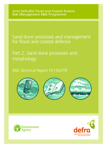
2.3SAMPLINGSix hundred and sixty two (662) bulk disturbed samples (B), two hundred and ninety one(291) small disturbed samples (D), eighteen (18) undisturbed 100mm dia. samples (U/U100),eleven (11) pavement cores, thirty three (33) grab samples (GB00) in the bed of the RiverSlaney at fifteen (15) locations at depths 0.0m, 0.5m, 1.0m and 1.5m and 587.6lin.m rotarycore were recovered from the exploratory holes in accordance with GeotechnicalInvestigation and Sampling – Sampling Methods and Groundwater Measurements (EN ISO22475-1:2006).Thirty one (31) environmental soil samples (ES, WAC and ENV) were recovered fromexploratory holes. Environmental samples were placed immediately in air-tight containers,which were filled to the top of the sample container. The sample suite consisted of: 2No. smalldisturbed samples (D) not less than 1.0kg, 2No. 250g amber glass sample containers and2No. 60g amber glass sample containers.2.4GROUNDWATER MONITORINGGroundwater was recorded when encountered/ observed during boring and trial pitexcavations over a period of 20 minutes, noting any changes that may occur. Groundwaterlevels were also monitored at start and end of drilling shifts. Groundwater is presented in atable in Section 5.It should be noted that the normal rate of boring may not permit the recording of equilibriumgroundwater levels for any one groundwater water strike where casing may exclude lowvolume flows as the borehole progresses. Groundwater conditions observed in the borings orpits are those appertaining to the period of the investigation. Groundwater levels may besubject to diurnal, seasonal and climatic variations and can also be affected by drainageconditions, tidal variations etc. The groundwater regime should be assessed from standpipewell installations, where available.Arisings backfill to boreholeBENTONITE grout backfillrotary boreholes/ installationP16087 RP INT F01GRAVEL backfill to installation/rotary boreholetouPVC slotted pipe621/12/2017
2.5IN SITU TESTINGStandard Penetration Tests, N values, were typically carried out in the boreholes using the60o solid cone (CPT) in place of the standard split barrel sampler. The Standard PenetrationTest was carried out in accordance with Geotechnical Investigation and Testing, Part 3Standard penetration test, BS EN ISO 22476-3:2005 A1:2011. The data was presented onthe relevant logs in APPENDIX A of the factual report.Static cone penetration tests, CPT were carried out by In Situ, Site Investigations Ltd (UK) onbehalf of PGL using CPT003, 3.5t tracked rig with cone 10cm2 at a rate of 2cms-1 to amaximum depth of 7.38m. The report “Enniscorthy Flood Relief Static Cone PenetrationTesting Factual Report” (ref: 1163055 November, 2016) is presented in APPENDIX B of thefactual report.The non-intrusive geophysical survey comprised of continuous 2D Electrical Resistivity(herein referred to as ERT), Seismic Refraction profiling. The survey fieldwork was carriedout by Minerex (MGX) on behalf of PGL. A separate report has been produced and ispresented in APPENDIX C of the factual report.In situ variable falling head permeability tests were carried out in 115mm, 131mm and200mm diameter borehole casing(s). In-situ permeability tests were carried out inaccordance with BS5930: 1999, Section 4: Cl. 25.4, within the superficial deposits over aduration of up to one (1) hour, as detailed on the borehole logs, APPENDIX A of the factualreport. The processed test data was presented on the relevant borehole logs presented inAPPENDIX A of the factual report. The shape or intake factor, f was derived from thecondition at the base of the borehole at the test depth and test geometry as per Hvorslev(1951).Generally for the tests the casing was withdrawn 0.5m giving an L/d between 1 to 13; so avalue of mean k (kH kV) was measured providing a shape factor, f of 7 to 20. In someinstances the casing was not withdrawn (L/d 0) and so a shape factor of 2.75 was provided.It shall be noted in some cases the permeability did not allow a hydraulic head to bedeveloped and so no assessment of permeability was made.P16087 RP INT F011021/12/2017
In situ hand vanes were carried out in trial pit excavations using 33mm vane. The data waspresented on the relevant logs (TP005 and TP007) in APPENDIX A of the factual report.Infiltration tests were carried out in general accordance with the BRE Digest 365, 2007Soakaway Design Standards. A single cycle of infiltration was undertaken and not the threecycles outlined in the standard. Soakaway pits failed to drain in full over the test duration upto 7hrs. The data from the testing was presented in APPENDIX A of the factual report,accompanying the relevant exploratory records.TRL dynamic probes (8kg drop weight, 575mm drop height) were carried out in pitexcavations to establish in situ California bearing ratio, CBR to depths between 0.19m bgl to1.88m bgl. The data from the testing was presented in APPENDIX A of the factual report,with the relevant trial pit records.SUMMARY OF IN-SITU TESTINGTypeQuantityRemarksStandard penetration test,629Nr.Uncorrected Nspt 0 – 139 (including refusalsNSPT valueIn situ permeability testBH (476)N presented a numerical value 50);RC (176)APPENDIX A of the factual report2.7 x10-3ms-1 to 2.4x10⁻⁷ ms-130Nr.APPENDIX A of the factual reportInfiltration/ Soakaway testsf 2.5 x 10⁻⁶ms-16Nr.to 2.1 x 10⁻⁴ ms-1APPENDIX A of the factual report5628lin.m 2D resMGX 6092f-005, January 20175995lin.m SeismicAPPENDIX C of the factual reportPlate loading tests3Nr.APPENDIX A of the factual reportDynamic probing (TRL)6Nr.TP003, TP004, TP018, TP019, TP021 andGeophysical surveyTP023; APPENDIX A of the factual reportIn situ hand vane,4Nr.TP005 (33mm) and TP007 (33mm).undrained shear strength10kPa to 29kPa; APPENDIX A of the factualreportIn situ CPT tests24Nr.Report(static cone penetration test)Dissipation testsP16087 RP INT F01Ref:1163055November,2016;APPENDIX B of the factual report3Nr.1121/12/2017
3 LABORATORY TESTINGAll samples were transported to Priority Geotechnical’s laboratory in Midleton, Co. Corkexamined, logged and prepared for scheduled testing. Laboratory testing was proposed byPGL, being reviewed and approved by Mott MacDonald. Testing was carried out by PGL, inaccordance with BS1377 (1990), Methods of test for soils for civil engineering purposes andthe ISRM suggested methods for rock characterisation, testing and monitoring. Specialistchemical testing was undertaken by Chemtest Ltd. (UK) on behalf of PGL. Specialist soil androck testing was carried out by GSTL Ltd (UK) on behalf of PGL. The laboratory test resultswere presented in APPENDIX C of the factual report. A summary of tests undertaken weredetailed below.SUMMARY OF LABORATORY TESTING UNDERTAKEN – SUPERFICIAL DEPOSITSSOILSTypeNo.Natural Moisture Content241Remarks4.4% to 209%Liquid limit, LL 26% to 163%Atterberg Limit173Plastic limit, PL 19% to 106% and NP non-plastic soilsPlasticity index, PI 7 to 72Particle Size Distribution (grading)326Grading by hydrometer97pH635.5 to 11.259 0.01g/l to 0.65g/l38 0.01% to .03%22 20mg/kg to 34mg/kg39 0.01g/l to 0.046g/l930.4% to 59%04 0.4% to 2.1%41Optimum moisture content 6% to 29%SO4 water solubleSO4 acid solubleChloride (extractable)Chloride water solubleLoss on ignitionOrganic contentProctorcompaction(MoistureSee APPENDIX D of the factual reportMaximum dry density 1.21Mg/m3 to 2.01Mg/m3content/dry density relationship)Moisture condition value, MCV700 – 10.4MCV moisture content relationship26APPENDIX D of the factual report BH101 0.0m; TP0040.5m, 1.5m; TP006 0.5m; TP007 1.5m; TP008 0.5m;TP012 0.5m; TP013 0.5m; TP014 0.5m, 1.5m; TP0271.0m; TP028 0.5m; TP029 0.5m, 2.0m, 3.0m; TP0312.6m; TP033 1.5m; TP035 0.5m; TPA03 0.5m, 1.6m;TPA04 0.3m, 1.0m; TPA05 0.5m, 2.0m; TPA06 1.5m;TPA08 1.5m.California Bearing Ratio, CBRP16087 RP INT F0123 1% to 28%1221/12/2017
SOILSTypeCBR Moisture content/dry densityrelationshipDirect shear (60mm sq shear box)No.0104RemarksTPA002 0.5m14o to 40o0kPa to 31kPaDirect shear (100mm sq shear box)0211o to 13o1kPa to 9kPa1D consolidation, oedometer01BHA06 1.0m, APPENDIX D of the factual report9.6 x 10 -10 ms-1 to 2.4 x 10 -8 ms-1Permeability – remoulded sample inTriaxial cell by back pressure14BHA051.0m, 2.0m; TPA01 1.2m; TPA02 1.5m; TPA052.0m; TP029 0.5m, 1.3m, 2.0m 3.0m; TP032 0.5m, 1.5m;TP035 0.5m; TPA03 1.6m; TPA06 0.6mPermeability – undisturbed sample inTriaxial cell by back pressurePermeability –remoulded sample –Constant head015 x 10 -10 ms-1BHA06 1.0m019 x 10 -6 ms-1TP008 1.5mPyrite suite02APPENDIX D of the factual reportWaste Acceptance Criteria, WAC47APPENDIX D of the factual reportSUMMARY OF LABORATORY TESTING UNDERTAKEN – SOLID GEOLOGYROCKTypeUniaxial Compressive Strength(UCS)UCS with Young’s Modulus andPoisson’s RatioNo.4303Point Load Test (IP50)194L.A. Abrasion02P16087 RP INT F01Remarks4.7MPa to 84.1MPa77.7GPa to 81.8GPa0.21 to 0.24(0.11MPa) 0.54MPa to 9.9MPaValues 0.5MPa considered unrealistically low)27 and 311321/12/2017
4 GROUND CONDITIONSThe full details of the ground conditions encountered are provided for on the exploratoryrecords accompanying this report. The records provide descriptions, in accordance with BS5930 (1999) A2: 2010 and Eurocode 7, Geotechnical Investigation and Testing,Identification and classification of soils, Part 1, Identification and description (EN ISO 146881: 2002),– Identification and Classification of Soil, Part 2: Classification Principles (EN ISO14688-2:2004) andIdentification and Classification of Rock, Part 1: Identification &Description (EN ISO 14689-1:2004) of the materials encountered, in situ testing and detailsof the samples taken, together with any observations made during the ground investigation.P16087 RP INT F011421/12/2017
5 GROUNDWATER CONDITIONSGroundwater was encountered during cable percussion drilling, during rotary drilling andexcavations between 1.6m bgl and 9.20m bgl. Details of the ground water and installationsare presented graphically on the relevant exploratory logs within APPENDIX A of the factualreport and are summarised below. See also section 3.4 for general details.Eighteen (16) number 50mm diameter standpipe well, installations were constructed to allowfor groundwater monitoring.SUMMARY OF GROUNDWATER INFORMATION OBTAINED DURING SITE WORKSLocationDept
Defence Scheme and the geotechnical interpretation of same. This report should be read in conjunction with the factual report and its appendices. Static cone penetration testing, CPT was carried out by In Situ Site Investigations Ltd (UK) on behalf of PGL. A report; "Enniscorthy Flood Relief Static Cone Penetration Testing