Transcription
Engineering UnitsMultiplesMicro ( )Milli (m)Kilo (k)Mega (M) 10-6 10-3 10 3 10 6Imperial unitsLengthAreaForcePressure/StressMultiple unitsLengthAreaForcePressure/Stressfeet(ft)square feet (ft2)pounds(p)2pounds/foot (psf)SI unitsmeter(m)square meter(m2)Newton(N)Pascal(Pa) (N/m2)inches(in)square feet (ft2)ton(t)2pounds/inch (psi)tons/foot2 (tsf)millimeter(mm)square millimeter (mm2)kilonewton(kN)2kilonewton/meter (kPa)meganewton/meter2 (MPa)Conversion factorsForce:1 ton1 kgPressure/Stress1kg/cm21 tsf1 t/m214.5 psi2.31 foot of water 9.8 kN 9.8 N 100 kPa 96 kPa 10 kPa 100 kPa 1 psi 100 kN/m2 1 bar( 100 kPa 0.1 MPa)1 meter of water 10 kPaDerived values from CPTFriction ratio:Rf (fs/qt) x 100%Corrected cone resistance:qt qc u2(1-a)Net cone resistance:qn qt – voExcess pore pressure: u u2 – u0Pore pressure ratio:Bq u / qnNormalized excess pore pressureU (ut – u0) / (ui – u0)where: ut is the pore pressure at time t in a dissipation test, andui is the initial pore pressure at the start of the dissipation test
Guide toIn-Situ TestingByP. K. RobertsonGregg Drilling & Testing Inc.January 2006
Gregg Drilling & Testing, Inc.Corporate Headquaters2726 Walnut AvenueSignal Hill, California 90755Telephone:Fax:E-mail:Website:(562) 427-6899(562) mThe publisher and the author make no warranties or representations of any kind concerning the accuracy orsuitability of the information contained in this guide for any purpose and cannot accept any legal responsibilityfor any errors or omissions that may have been made.Copyright 2006 Gregg Drilling & Testing, Inc. All rights reserved.
Table of ContentsGlossaryiIntroduction1Risk Based Site Characterization2In-Situ Tests3Cone Penetration Test (CPT)4Introduction7History8Test Equipment and Procedures11Additional Sensors/Modules12Pushing Equipment13Depth of Penetration17Test Procedures17CPT InterpretationSoil Profiling and ClassificationEquivalent SPT N60 ProfilesUndrained Shear Strength (su)Soil SensitivityOverconsolidation Ratio (OCR)In-Situ Stress Ratio (Ko)Friction AngleRelative Density (Dr)Stiffness and ModulusModulus From Shear Wave VelocityIdentification of Unusual Soils Using the SCPTHydraulic Conductivity (k)Consolidation Characteristics2021252829303132343637383942CPT ApplicationsShallow FoundationsDeep FoundationsLiquefaction AssessmentCompaction Control4545464647New Developments47
Standard Penetration Test (SPT)48Introduction48History48Test Equipment and Procedures48Factors Affecting the SPTDrilling and Borehole TechniquesSPT EquipmentTest Procedure51515255Factors Affecting Interpretation of the SPT56SPT InterpretationRelative DensityFriction AngleStiffness and ModulusUndrained Shear StrengthStress History (OCR)Compressibility61626364666768SPT ApplicationsShallow FoundationsDeep FoundationsLiquefaction AssessmentCompaction ControlSPT in Soft Rocks697070707171New Developments72Field Vane Test (FVT)73Flat Dilatometer Test (DMT)77Pressuremeter Test (PMT)80Main References86
Guide to In-Situ Testing - 2006GlossaryGlossaryThis glossary contains the most commonly used terms related to CPT and arepresented in alphabetical order.CPTCone penetration test.CPTUCone penetration test with pore pressure measurement – piezocone test.ConeThe part of the cone penetrometer on which the cone resistance ismeasured.Cone penetrometerThe assembly containing the cone, friction sleeve, and any other sensorsand measuring systems, as well as the connections to the push rods.Cone resistance, qcThe force acting on the cone, Qc, divided by the projected area of thecone, Ac.qc Qc / AcCorrected cone resistance, qtThe cone resistance qc corrected for pore water effects.qt qc u2(1- an)Data acquisition systemThe system used to record the measurements made by the conepenetrometer.Dissipation testA test when the decay of the pore pressure is monitored during a pause inpenetration.Filter elementThe porous element inserted into the cone penetrometer to allowtransmission of pore water pressure to the pore pressure sensor, whilemaintaining the correct dimensions of the cone penetrometer.Friction ratio, RfThe ratio, expressed as a percentage, of the sleeve friction, fs, to the coneresistance, qt, both measured at the same depth.Rf (fs/qt) x 100%i
Guide to In-Situ Testing - 2006GlossaryFriction reducerA local enlargement on the push rods, placed a short distance above thecone penetrometer, to reduce the friction on the push rods.Friction sleeveThe section of the cone penetrometer upon which the sleeve friction ismeasured.Normalized cone resistance, QtThe cone resistance expressed in a non-dimensional form and takingaccount of the in-situ vertical stresses.Qt (qt – σvo) / σ'voNet cone resistance, qnThe corrected cone resistance minus the vertical total stress.qn qt – σvoExcess pore pressure (or net pore pressure), ΔuThe measured pore pressure less the in-situ equilibrium pore pressure.Δu u2 – u0Pore pressureThe pore pressure generated during cone penetration and measured by apore pressure sensor:u1 when measured on the coneu2 when measured just behind the cone, and,u3 when measured just behind the friction sleeve.Pore pressure ratio, BqThe net pore pressure normalized with respect to the net cone resistance.Bq Δu / qnPush rodsThick-walled tubes used to advance the cone penetrometerPush (thrust) machineThe equipment used to push the cone penetrometer and push rods into theground.Sleeve friction, fsThe frictional force acting on the friction sleeve, Fs, divided by its surfacearea, As.fs Fs / Asii
Guide to In-Situ Testing - 2006IntroductionIntroductionThe purpose of this guide is to provide a concise summary on in-situ testing andits application to geotechnical engineering. The aim of in-situ testing is todefine soil stratigraphy and obtain measurements of soil response andgeotechnical parameters.The common in-situ tests include: Standard Penetration Test (SPT), ConePenetration Test (CPT), Flat Plate Dilatometer (DMT), Field Vane Test (FVT)and Pressuremeter Test (PMT). Each test applies different loading schemes tomeasure the corresponding soil response in an attempt to evaluate materialcharacteristics such as strength and stiffness. Boreholes are required for theSPT and some versions of the PMT and FVT. For the CPT and DMT noboreholes are needed and the term ‘direct-push’ is often used. An advantage ofdirect-push technology is that no cuttings are generated. However, adisadvantage of the direct-push method is that hard cemented layers, bedrock,and some gravel layers can prevent further penetration.The guide has an emphasis on the Cone Penetration Test (CPT) and theStandard Penetration Test (SPT), since these are the most commonly used insitu tests in North America. The section on the CPT is a supplement to thebook ‘CPT in Geotechnical Practice’ by Lunne, Robertson and Powell (1997)and is applicable primarily to data obtained using a standard electronic conewith a 60-degree apex angle and a diameter of either 35.7 mm or 43.7 mm (10cm2 or 15 cm2 cross-sectional area). The section on the SPT is applicable to dataobtained following ASTM standard D1586-99.A list of useful references is included at the end of this guide.1
Guide to In-Situ Testing – 2006Risk Based Site CharacterizationRisk Based Site CharacterizationRisk and uncertainty are characteristics of the ground and are never fullyeliminated. The extent and level of an investigation should be based on the riskof the project. Risk analysis answers three basic questions, namely: What can go wrong? How likely is it? What are the consequences?Projects can be classified into low, moderate or high risk projects, depending onthe probability of the associated hazards occurring and the associatedconsequences. Low-risk projects could be projects with few hazards, lowprobability of occurrence, and limited consequences, whereas high risk projectscould be projects with many hazards, a high probability of occurrence, andsevere consequences. Table 1 shows a generalized flow chart to illustrate thelikely geotechnical ground investigation approach associated with low risk,moderate risk and high risk projects.P R O JE C TP re lim in a ry S ite E v a lu a tio ne .g . g e o lo g ic m o d e l, d e s k s tu d y ,ris k a s s e s s m e n tL O W R IS KM O DERATER IS KG ro u n d In v e s tig a tio nG ro u n d In v e s tig a tio nIn -s itu te s tin g& D is tu rb e d s a m p le sS a m e a s fo r lo w ris kp ro je c ts , p lu s th e fo llo w in g : In -s itu te s tin ge .g . S P T , C P T (S C P T u ),DMTA d d itio n a l s p e c ificin -s itu te s tse .g . P M T , F V T E m p iric a l c o rre la tio n sd o m in a teP re lim in a ry g ro u n din v e s tig a tio nD e ta ile dg ro u n din v e s tig a tio nS a m e a s fo r lo w ris kp ro je c ts , p lu s th e fo llo w in g :In -s itu te s tin gA d d itio n a l in -s itu te s ts&H ig h q u a lityu n d is tu rb e d s a m p le s Id e n tify c ritic a lzones P o s s ib ly s p e c ific te s ts In d e x te s tin ge .g . A tte rb e rg lim its , g ra ins iz e d is trib u tio n , e m in /e m a x , G sH IG H R IS KS ites p e c ificc o rre la tio nH ig h q u a lity la b o ra to ryte s tin g (re s p o n s e )B a s ic la b o ra to ryte s tin g o n s e le c te db u lk s a m p le s(re s p o n s e )S ites p e c ificc o rre la tio n U n d is tu rb e d s a m p le sIn -s itu s tre s s e sA p p ro p ria te s tre s s p a thC a re fu l m e a s u re m e n tsTable 1 Risk-based flowchart for site characterization.2
Guide to In-Situ Testing – 2006In-Situ TestsIn-Situ TestsThe objectives of any subsurface investigation are to determine the following: Nature and sequence of the subsurface strata (geologic regime) Groundwater conditions (hydrologic regime) Physical and mechanical properties of the subsurface strataFor geo-environmental site investigations where contaminants are possible, theabove objectives have the additional requirement to determine: Distribution and composition of contaminantsThe above requirements are a function of the proposed project and theassociated risks. An ideal investigation program should include a mix of fieldand laboratory tests depending on the risk of the project.Table 2 presents a partial list of the major in-situ tests and their perceivedapplicability for use in different ground conditions.Table 2 The applicability and usefulness of in-situ tests(Lunne, Robertson & Powell, 1997)3
Guide to In-Situ Testing – 2006Cone Penetration Test (CPT)Cone Penetration Test (CPT)The Cone Penetration Test (CPT) and it’s enhanced versions (i.e. piezoconeCPTU and seismic-SCPT) have extensive applications in a wide range ofsoils. Although the CPT is limited primarily to softer soils, with modernlarger pushing equipment and more robust cones, the CPT can be performedin stiff to very stiff soils, and in some cases soft rock.Advantages of CPT: Fast and continuous profiling Repeatable and reliable data (not operator-dependent) Economical and productive Strong theoretical basis for interpretationDisadvantage of CPT: High capital investment Requires skilled operators No soil sample Penetration can be restricted in gravel/cemented layersThe Standard Penetration Test (SPT)The Standard Penetration Test (SPT) is used as an indicator of relativedensity and stiffness of granular soils as well as an indicator of consistencyin a wide range of other ground. Methods have been developed to applySPT results to a wide range of geotechnical applications including shallowand deep foundations and the assessment of liquefaction potential.Advantages of SPT: Simple and rugged Low cost Obtain a sample Can be performed in most soil types Available throughout the U.S.4
Guide to In-Situ Testing – 2006Cone Penetration Test (CPT)Disadvantages of SPT: Disturbed sample (index tests only) Crude number (N value) Not applicable in soft clays and silts High variability and uncertainty.The Field Vane Test (FVT)The field vane test (FVT) is used to evaluate the undrained shear strength(suv) of soft to stiff clays and silts. Both peak and remolded strengths can bemeasured and their ratio is termed soil sensitivity (St).Advantages of FVT: Simple test and equipment Long history of use in practiceDisadvantages of FVT: Limited application to soft to stiff clays and silts Slow and time-consuming Raw suv values need (empirical) correction Can be affected by sand lenses and seams.The Flat Plate Dilatometer Test (DMT)The flat plate dilatometer test (DMT) can be used to estimate a wide range ofgeotechnical parameters in primarily softer soils.Advantages of DMT: Simple and robust Repeatable and reliable data (not operator-dependent) EconomicalDisadvantage of DMT: Difficult to push into dense and hard materials Weak theoretical basis for interpretation No soil sample Penetration can be restricted in gravel/cemented layers5
Guide to In-Situ Testing – 2006Cone Penetration Test (CPT)The Pressuremeter Test (PMT)The pressuremeter test can be used to evaluate the stress-strain response of awide range of soils and rock. There are three basic types of pressuremeterdevices, Pre-bored, Self-bored and Full-displacement, each with differentabilities and challenges. In general they have the following advantages anddisadvantages:Advantages of PMT: Strong theoretical basis for interpretation Tests large volume of groundDisadvantages of PMT: Complicated equipment and procedures Requires skilled operator Time consuming and expensive Equipment can be easily damaged6
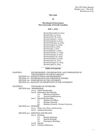
Guide to In-Situ Testing – 2006Cone Penetration Test (CPT)Cone Penetration Test (CPT)IntroductionIn the Cone Penetration Test (CPT), a cone on the end of a series of rods ispushed into the ground at a constant rate and continuous measurements aremade of the resistance to penetration of the cone and of a surface sleeve.Figure 1 illustrates the main terminology regarding cone penetrometers.The total force acting on the cone, Qc, divided by the projected area of thecone, Ac, produces the cone resistance, qc. The total force acting on thefriction sleeve, Fs, divided by the surface area of the friction sleeve, As,produces the sleeve friction, fs.In a piezocone, pore pressure is alsomeasured, as shown in Figure 1.Figure 1 Terminology for cone penetrometers7
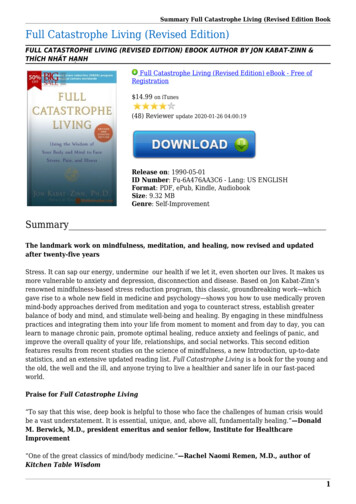
Guide to In-Situ Testing – 2006Cone Penetration Test (CPT)History1932The first cone penetrometer tests were made using a 35 mm outside diametergas pipe with a 15 mm steel inner push rod. A cone tip with a 10 cm2projected area and a 60o apex angle was attached to the steel inner push rods,as shown in Figure 2.Figure 2 Early Dutch mechanical cone (After Sanglerat, 1972)1935Delf Soil Mechanics Laboratory designed the first manually operated 10 toncone penetration push machine, see Figure 3.Figure 3 Early Dutch mechanical cone (After Delft Geotechnics)8
Guide to In-Situ Testing – 2006Cone Penetration Test (CPT)1948Improvement of the original Dutch mechanical cone by adding a conical partjust above the cone. The purpose of the geometry was to prevent soil fromentering the gap between the casing and inner rods. The basic Dutchmechanical cones, shown in Figure 4, are still in use in some parts of theworld.Figure 4 Dutch mechanical cone penetrometer with conical mantle1953Addition of a friction sleeve (‘adhesion jacket’) behind the cone to includemeasurement of the local sleeve friction (Begemann, 1953), see Figure 5.Measurements were made every 8 inches (20 cm), and for the first time,friction ratio was used to classify soil type (see Figure 6).Figure 5 Begemann type cone with friction sleeve9
Guide to In-Situ Testing – 2006Cone Penetration Test (CPT)Figure 6 First soil classification for Begemann mechanical cone1965Development of an electric cone by Fugro, of which the shape anddimensions formed the basis for the modern cones and the InternationalReference Test and ASTM procedure. The main improvements relative tothe mechanical cone penetrometers are: Elimination of incorrect readings due to friction between inner rodsand outer rods and weight of inner rods. Continuous testing with continuous rate of penetration without theneed for alternate movements of different parts of the penetrometerand no undesirable soil movements influencing the cone resistance. Simpler and more reliable electrical measurement of cone resistanceand sleeve friction.1974Introduction of cone penetrometers that could also measure pore pressure(piezocone). Early design had various shapes and pore pressure filterlocations. Gradually the practice has become more standardized so that therecommended position of the filter element is close behind the cone at the u2location. With the measurement of pore water pressure it became apparentthat it was necessary to correct the cone resistance for pore water pressureeffects (qt), especially in soft clay.10
Guide to In-Situ Testing – 2006Cone Penetration Test (CPT)Test Equipment and ProceduresCone PenetrometersCone penetrometers come in a range of sizes with the 10 cm2 and 15 cm2probes the most common and specified in most standards. Figure 7 shows arange of cones from a mini-cone at 2 cm2 to a large cone at 40 cm2. Themini cones are used for shallow investigations, whereas the large cones canbe used in gravely soils.Figure 7 Range of CPT probes (from left: 2 cm2, 10 cm2, 15 cm2, 40 cm2)11
Guide to In-Situ Testing – 2006Cone Penetration Test (CPT)Additional Sensors/ModulesSince the introduction of the electric cone in the early 1960’s, manyadditional sensors have been added to the cone, such as; TemperatureGeophones (seismic wave velocity)PressuremeterCamera (visible light)Radioisotope (gamma/neutron)Electrical resistivity/conductivityDielectricpHOxygen exchange (redox)Laser/ultraviolet induced fluorescenceMembrane interface probe (MIP)The latter items are primarily for geo-environmental applications.One of the more common additional sensors is a geophone to allow themeasurement of seismic wave velocities. A schematic of the seismic CPT(SCPT) is shown in Figure 8.Figure 8 Schematic of Seismic CPT (SCPT)12
Guide to In-Situ Testing – 2006Cone Penetration Test (CPT)Pushing EquipmentPushing equipment consists of push rods, a thrust mechanism and a reactionframe.On LandPushing equipment for on land applications generally consist of speciallybuilt units that are either truck or track mounted. CPT’s can also be carriedout using an anchored drill-rig. Figures 9 to 12 show a range of on landpushing equipment.Figure 9 Truck mounted 25 ton CPT unit13
Guide to In-Situ Testing – 2006Cone Penetration Test (CPT)Figure 10 Track mounted 20 ton CPT unitFigure 11 Small anchored drill-rig unit14
Guide to In-Situ Testing – 2006Cone Penetration Test (CPT)Figure 12 Ramset for CPT inside buildings or limited access15
Guide to In-Situ Testing – 2006Cone Penetration Test (CPT)Over waterThere is a variety of pushing equipment for over water investigationsdepending on the depth of water. Floating or Jack-up barges are common inshallow water (depth less than 80 feet), see Figures 13 and 14.Figure 13 Mid-size jack-up bargeFigure 14 Quinn Delta ship with spuds16
Guide to In-Situ Testing – 2006Cone Penetration Test (CPT)Rate of PenetrationThe standard rate of penetration is 2 cm per second, which is approximately1 inch per second. Hence, a 60 foot sounding can be completed (start tofinish) in about 30 minutes. The cone results are generally not sensitive toslight variations in the rate of penetration.Interval of ReadingsElectric cones produce continuous analogue data. However, most systemsconvert the data to digital form at selected intervals. Most standards requirethe interval to be no more than 8 inches (200mm). In general, most systemscollect data at intervals of between 1 to 2 inches (25 - 50mm), with 2 inchesthe most common.Dissipation TestsDuring a pause in penetration, any excess pore pressure generated aroundthe cone will start to dissipate. The rate of dissipation depends upon thecoefficient of consolidation, which in turn, depends on the compressibilityand permeability of the soil. The rate of dissipation also depends on thediameter of the probe. A dissipation test can be performed at any requireddepth by stopping the penetration and measuring the decay of pore pressurewith time. If equilibrium pore pressures are required, the dissipation testshould continue until no further dissipation is observed. This can occurrapidly in sands, but may take several days in plastic clays. Dissipation isfaster for smaller cones.Calibration and MaintenanceCalibrations should be carried out at regular intervals (approximately every3 months). For major projects, calibrations should be carried out before andafter the field work, with functional checks during the work. Functionalchecks should include recording and evaluation of zero load measurements.18
Guide to In-Situ Testing – 2006Cone Penetration Test (CPT)With careful design, calibration, and maintenance, strain gauge load cellsand pressure transducers can have an accuracy and repeatability of betterthan /- 0.2% of full scale reading.MaintenanceStartStart ofofTestProjectWearxO-ring sealsxPush-rodsPorepressure-filterEnd ofTestEnd ofDayxEvery 3monthsxxxxOnce xxxTable 3 Summary of checks and recalibrations for the CPTPore Water EffectsIn soft clays and silts and in over water work, the measured qc must becorrected for pore water pressures acting on the cone geometry, thusobtaining the corrected cone resistance, qt:qt qc u2 (1 – an)where an is the net area ratio determined from laboratory calibration.19
Guide to In-Situ Testing – 2006Cone Penetration Test (CPT)CPT InterpretationNumerous semi-empirical correlations have been developed to estimategeotechnical parameters from the CPT for a wide range of soil. Thesecorrelations vary in their reliability and applicability. Because the CPT hasadditional sensors (e.g. pore pressure: CPTU and seismic: SCPT), theapplicability to estimate soil parameters varies. Since CPT with porepressure measurements (CPTU) is commonly available, Table 4 shows anestimate of the perceived applicability of the CPTU to estimate soilparameters. If seismic is added, the ability to estimate soil stiffness (E, G &Go) improves further.SoilTypeDrΨSand2-32-3ClayKo OCRStsu52121-2φE,G*2-33-443-4M G0*kch2-333-443-4 2-3 2-3Table 4 Perceived applicability of CPTU for deriving soil parameters1 high; 2 high to moderate; 3 moderate; 4 moderate to low; 5 low reliability;Blank no applicabilityWhere:DrRelative densityΨState ParameterE, G Young’s and Shear moduliOCR Over consolidation ratiosuUndrained shear strengthcHCoefficient of consolidation20φFriction angleIn-situ stress ratioK0G0Small strain shear moduliM (or mv) CompressibilityStSensitivitykPermeability
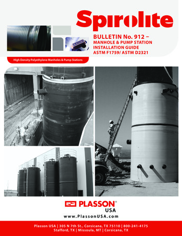
Guide to In-Situ Testing – 2006Cone Penetration Test (CPT)Soil Profiling and ClassificationThe major application of the CPT is for soil profiling and classification.Typically, the cone resistance, (qt) is high in sands and low in clays, and thefriction ratio (Rf fs/qt) is low in sands and high in clays. CPT classificationcharts cannot be expected to provide accurate predictions of soil type basedon grain size distribution but provide a guide to the mechanicalcharacteristics of the soil, or the soil behavior type (SBT). CPT dataprovides a repeatable index of the aggregate behavior of the in-situ soil inthe immediate area of the probe. Hence, prediction of soil type based onCPT is referred to as soil behavior type (SBT).Non-Normalized ChartsThe most commonly used CPT soil behavior type method is the chartsuggested by Robertson et al. (1986) and shown in Figure 15. This chartuses the basic CPT parameters of cone resistance, qt and friction ratio, Rf.The chart is global in nature and can provide reasonable predictions of soilbehavior type for CPT soundings up to about 60ft (20m) in depth. The chartidentifies general trends in ground response such as increasing relativedensity (Dr) for sandy soils, increasing stress history (OCR), soil sensitivity(St) and void ratio (e) for cohesive soils. Overlap in some zones should beexpected and the zones should be adjusted somewhat based on localexperience.Normalized ChartsSince both the penetration resistance and sleeve friction increase with depthdue to the increase in effective overburden stress, the CPT data requiresnormalization for overburden stress for very shallow and/or very deepsoundings.A popular CPT soil classification chart based on normalized CPT data is thatproposed by Robertson (1990) and shown in Figure 16. A zone has beenidentified in which the CPT results for most young, un-cemented,insensitive, normally consolidated soils will fall. Again the chart is global innature and provides only a guide to soil behavior type (SBT). Overlap insome zones should be expected and the zones should be adjusted somewhatbased on local experience.21
Guide to In-Situ Testing – 2006Cone Penetration Test (CPT)Zone123456789101112Soil Behavior TypeSensitive fine grainedOrganic materialClaySilty Clay to clayClayey silt to silty claySandy silt to clayey siltSilty sand to sandy siltSand to silty sandSandGravelly sand to sandVery stiff fine grained*Sand to clayey sand** Overconsolidated or cemented1 MPa 10 tsfFigure 15 CPT Soil Behavior Type (SBT) chart(Robertson et al., 1986).22
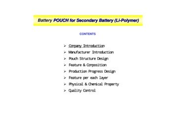
Guide to In-Situ Testing – 2006Zone123456789Cone Penetration Test (CPT)Soil Behavior TypeSensitive, fine grainedOrganic soils – peatsClays – silty clay to claySilt mixtures – clayey silt tosilty claySand mixtures – silty sand tosandy siltSands – clean sand to siltysandGravelly sand to dense sandVery stiff sand to clayey sand*Very stiff, fine grained*IcN/A 3.62.95 – 3.62.60 – 2.952.05 – 2.61.31 – 2.05 1.31N/AN/A* Heavily overconsolidated or cementedFigure 16 Normalized CPT Soil Behavior Type (SBTN) chart(Robertson, 1990).23
Guide to In-Situ Testing – 2006Cone Penetration Test (CPT)If no prior CPT experience exists in a given geologic environment it isadvisable to obtain samples from appropriate locations to verify theclassification and soil behavior type. If significant CPT experience isavailable and the charts have been modified based on this experiencesamples may not be required.Soil classification can be improved if pore pressure data is also collected. Insoft clay the penetration pore pressures can be very large, whereas, in stiffheavily over-consolidated clays or dense silts and silty sands the penetrationpore pressures can be small and sometimes negative relative to theequilibrium pore pressures (u0). Also the rate of pore pressure dissipationduring a pause in penetration can guide in the soil type. In sandy soils anyexcess pore pressures will dissipate very quickly, whereas, in clays the rateof dissipation can be very slow.To simplify the application of the CPT SBTN chart shown in Figure 16, thenormalized cone parameters Qt and Fr can be combined into one SoilBehavior Type index, Ic, where Ic is the radius of the essentially concentriccircles that represent the boundaries between each SBT zone. Ic can bedefined as follows;Ic ((3.47 - log Qt)2 (log Fr 1.22)2)0.5where:Qt Fr the normalized cone penetration resistance (dimensionless)(qt – σvo)/σ'vothe normalized friction ratio, in %(fs/(qt – σvo)) x 100%The boundaries of soil behavior types are then given in terms of the index,Ic, as shown in Figure 16. The soil behavior type index does not apply tozones 1, 8 and 9. Profiles of Ic provide a simple guide to the continuousvariation of soil behavior type in a given soil profile based on CPT results.Independent studies have shown that the normalized SBTN chart shown inFigure 16 typically has greater than 80% reliability when compared tosamples.24
Guide to In-Situ Testing – 2006Cone Penetration Test (CPT)Equivalent SPT N60 ProfilesThe Standard Penetration Test (SPT) is one of the most commonly used insitu tests in many parts of the world, especially North America. Despitecontinued efforts to standardize the SPT procedure and equipment there arestill problems associated with its repeatability and reliability. However,many geotechnical engineers have developed considerable experience withdesign methods based on local SPT correlations. When these engineers arefirst introduced to the CPT they initially prefer to see CPT results in theform of equivalent SPT N-values. Hence, there is a need for reliableCPT/SPT correlations so that CPT data can be used in existing SPT-baseddesign approaches.There are many factors affecting the SPT results, such as, boreholepreparation and size, sampler details, rod length and energy efficiency of thehammer-anvil-operator system. One of the most significant factors is theenergy efficiency of the SPT system. This is normally expressed in terms ofthe rod energy ratio (ERr). An energy ratio of about 60% has generally beenaccepted as the reference value which represents the approximate historicalaverage SPT energy.A number of studies have been presented over the years to relate the SPT Nvalue to the CPT cone penetration resistance, qc. Robertson et al. (1983)reviewed these correlations and presented the relationship shown in Figure17 relating the ratio (qc/pa)/N60 with mean grain size, D50 (varying between0.001mm to 1mm). Values of qt are made dimensionless when dividing bythe atmospheric pressure (pa) in the same units as qc. It is observed that theratio increases with increasing grain size.The values of N used by Robertson et al. correspond to an average energyratio of about 60%. Hence, the ratio applies to N60, as shown on Figure 17.Other studies have linked the ratio between the CPT and SPT with finescontent for sandy soils.25
Guide to In-Situ Testing – 2006Cone Penetration Test (CPT)Figure 17 CPT-SPT correlations with mean grain size(Robertso
The guide has an emphasis on the Cone Penetration Test (CPT) and the Standard Penetration Test (SPT), since these are the most commonly used in-situ tests in North America. The section on the CPT is a supplement to the book 'CPT in Geotechnical Practice' by Lunne, Robertson and Powell (1997)