Transcription
Intel’s Core 2 family - TOCK lines IINehalem to HaswellDezső SimaVers. 3.11August 2018
Contents 1. Introduction 2. The Core 2 line 3. The Nehalem line 4. The Sandy Bridge line 5. The Haswell line 6. The Skylake line 7. The Kaby Lake line 8. The Kaby Lake Refresh line 9. The Coffee Lake line 10. The Cannon Lake line
3. The Nehalem line 3.1 Introduction to the 1. generation Nehalem line(Bloomfield) 3.2 Major innovations of the 1. gen. Nehalem line 3.3 Major innovations of the 2. gen. Nehalem line(Lynnfield)
3.1 Introduction to the 1. generation Nehalem line(Bloomfield)
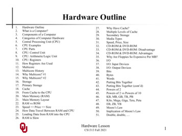
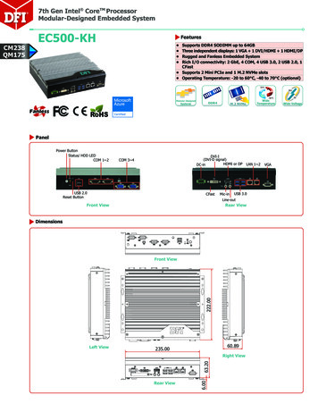
3.1 Introduction to the 1. generation Nehalem line (Bloomfield) (1)3.1 Introduction to the 1. generation Nehalem line (Bloomfield)Developed at Hillsboro, Oregon, at the site where the Pentium 4 was designed.Experiences with HTNehalem became a multithreaded design.The design effort took about five years and required thousands of engineers(Ronak Singhal, lead architect of Nehalem) [37].The 1. gen. Nehalem line targets DP servers, yet its first implementation appeared in thedesktop segment (Core i7-9xx (Bloomfield)) 4C in 11/20081. gen.2. gen.3. gen.4. gen.5. gen.HaswellBroadwellCore .NewProcess65 nm45 nm45 nm32 nm32 nm22 nm22 nm14 re : Intel’s Tick-Tock development model (Based on [1])NewProcess*
3.1 Introduction to the 1. generation Nehalem line (Bloomfield) (2)Nehalem lines1. generation Nehalem processors2. generation Nehalem processorsMobilesMobilesCore i7-9xxM (Clarksfield) 4C 9/2009Core i7-8xxQM (Clarksfield) 4C 9/2009Core i7-7xxQM (Clarksfield) 4C 9/2009DesktopsDesktopsCore i7-9x0 (Bloomfield) 4C 11/2008HEDCore i7-8xx (Lynnfield) 4C 9/2009Core i5-7xx (Lynnfield) 4C 9/2009Core i7-965 (Bloomfield) 4C 11/2008Core i7-975 (Bloomfield) 4C 7/2009ServersUP-Servers35xx (Bloomfield) 4C 3/2009DP-Servers55xx (Gainestown) (Nehalem-EP) 4C 3/2009Based on [44]ServersUP-Servers34xx (Lynnfield) 4C 9/2009C35xx (Jasper forest1) 4C 2/2010DP-ServersC55xx (Jasper forest1) 2C/4C 2/20101Jasperforest: Embedded UP or DP server
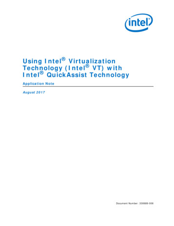
3.1 Introduction to the 1. generation Nehalem line (Bloomfield) (3)Die shot of the 1. generation Nehalem desktop processor (Bloomfield) [45](8 MB)Die shot of the Bloomfield chip [45]Note Both the desktop oriented Bloomfield chip and the DP server oriented Gainestown chip havethe same layout. The Bloomfield die has two QPI bus controllers, in spite of the fact that they are not neededfor the desktop part.In the Bloomfield die one of the controllers is simply not activated [45], whereas both areactive in the DP alternative (Gainestown).*
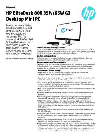
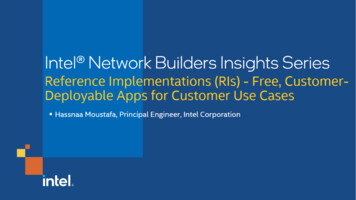
3.1 Introduction to the 1. generation Nehalem line (Bloomfield) (4)TICK Pentium 4 ( Cedar Mill)Pentium D (Presler)65nmCore 201/2006TICK Penryn FamilyTOCK Nehalem11/2008TICK Westmere01/2010TICK Ivy Bridge?4 YEARS2 YEARS07/20062 YEARSTOCKKey new features of the ISAand the microarchitecture2 YEARS22 YEARSYEARSThe Nehalem line -1 (based on [3])45nm11/200732nmTOCK Sandy Bridge01/2011TOCK Haswell06/2013TICK Broadwell09/2014TOCK Skylake10/2015TOCK Kaby Lake RefreshNew microarch.: 4 cores, integr. MC,QPI, private L2, (inclusive) L3, HTIn package integrated GPUNew microarch.: 256-bit (FP) AVX,ring bus, integrated GPU04/201222nmTOCK Kaby LakeNew microarch.: 4-wide core,128-bit SIMD FX/FP EUs,shared L2 , no HT14nm14nm08/2016New microarch.: 256-bit (FX) AVX2,L4 cache (discrete eDRAM), TSXShared Virtual MemoryNew microarch.: 5-wide core,ISP, Memory Side L4 cache, no FIVROptane memory, in KBL G series:in package integr. CPU, GPU, HBM208/20176C, (PCHs of S-series DTs support:USB G2, integr. conn., Optane 2)TOCK Coffee Lake10/2017TOCK Coffee Lake Refresh10/20188C05/2018AVX512TICK Cannon Lake10nm10nm
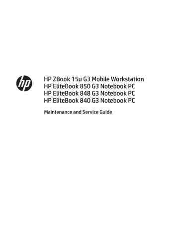
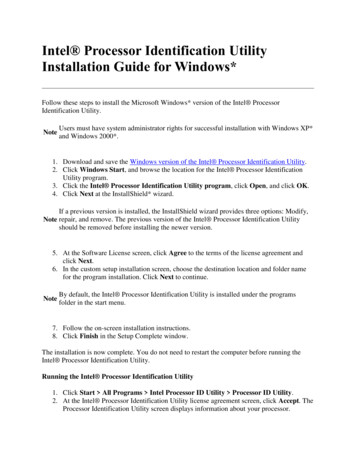
3.1 Introduction to the 1. generation Nehalem line (Bloomfield) (4B)TICK Pentium 4 ( Cedar Mill)Pentium D (Presler)2 YEARSTICK WestmereTICK Ivy Bridge4 YEARSTICK Penryn Family?Key new featuresof the power management65nmCore 22 YEARSTOCK2 YEARS22 YEARSYEARSThe Nehalem line -2 (based on [3])01/200607/200645nmTOCK Nehalem11/200711/2008TOCK Sandy Bridge01/2011Turbo Boost 2.004/201222nmTOCK Haswell06/2013TICK Broadwell09/2014TOCK Skylake10/2015TOCK Kaby Lake RefreshIntegrated Power Gates, PCU,Turbo Boost01/201032nmTOCK Kaby LakeClock gating, PECI,Platform Thermal Control by3. party controllerEDAT14nm14nm08/2016FIVR2. gen. FIVRSpeed Shift Technology,Duty Cycle control, No FIVRexcept Skylake XSpeed Shift Technology v208/2017TOCK Coffee Lake10/2017In H-series: TVB(Thermal Velocity Boost)TOCK Coffee Lake Refresh10/2018STIMTICK Cannon Lake10nm10nm05/2018
3.2 Major innovations of the 1. generation Nehalem line 3.2.1 Integrated memory controller 3.2.2 QuickPath Interconnect bus (QPI) 3.2.3 New cache architecture 3.2.4 Simultaneous Multithreading 3.2.5 Enhanced power management 3.2.6 New socket
3.2 Major innovations of the 1. generation Nehalem line (1)3.2 Major innovations of the 1. generation Nehalem line [54] The Major incentive for designing the microarchitecture of Nehalem: support of 4 cores. 4 cores need however twice as much bandwidth as dual core processors, to maintain theper core memory bandwidth. Two memory channels used for dual core processors are more or less the limit attachable tothe north bridge due to physical and electrical limitations.Consequently, to provide enough bandwidth for 4 cores, a new memory design was necessary.Major innovations of the 1. generation 4-core Nehalem line Integrated memory controller(Section 3.2.1) QuickPath Interconnect bus (QPI)(Section 3.2.2) New cache architectureure(Section 3.2.3) Simultaneous Multithreading (SMT)(Section 3.2.4) SSE 4.2 ISA extension(Not detailed) Enhanced power management(Section 3.2.5) Advanced virtualization(Not detailed) New socket(Section 3.2.6)(8 MB)Figure 3.2.1: Die photo of the Bloomfield/Gainestown chip*
3.2.1 Integrated memory controller (1)3.2.1 Integrated memory controller Traditional system architectures, as shown below for the Core 2 Duo processor, canimplement not more than two high speed memory channels connected to the MCHdue to electrical and physical constraints, to be discussed in Chapter on Intel’s Servers.Two memory channels can however, provide enough bandwidth only for up to dual core processors.Figure: Core 2 Duo basedplatform [166]*
3.2.1 Integrated memory controller (2)The need for integrated memory controller in a dual processor QC Nehalem platformn coresn times higher memory bandwidth need per processorNew design for attaching memory: placing memory controllers on the diesDDR3DDR3Figure 3.2.1.1: Integrated memory controller of Nehalem [33]*
3.2.1 Integrated memory controller (2b)Connecting 3 DDR3memory channels to theprocessor socket [242]
3.2.1 Integrated memory controller (2c)Alternative solution: Connecting memory via (connected via low-line count serialdifferential interfaces)(Harpertown (2x2 cores, 45 nm Penryn) based DP server processor [277]Harpertown(45 nm, 2 chipsin the same package)FB-DIMM memory(connected vialow-line countserial differentialinterfaces)
3.2.1 Integrated memory controller (3)Benefits and drawback of integrated memory controllersBenefitsLow memory access latencyimportant for memory intensive apps.Drawback of integrated memory controllers Processor becomes memory technology dependent For an enhanced memory solution (e.g. for increased memory speed)a new processor modification is needed.*
3.2.1 Integrated memory controller (4)Non Uniform Memory Access (NUMA) architecturesIt is a consequence of using integrated memory controllers in case of multi-socket serversLocal memory accessRemote memory accessFigure 3.2.1.2: Non Uniform Memory Access (NUMA) in multi-socket servers [1] Advanced multi-socket platforms use NUMARemote memory access latency 1.7 x longer than local memory access latencyDemands a fast processor-to-processor interconnection to relay memory traffic (QPI)Operating systems have to modify memory allocation strategies related APIs*
3.2.1 Integrated memory controller (4b)Remark: Classification of multiprocessor server platforms according to theirmemory architectureMultiprocessor server platformsclassified according to their memory architectureSMPs(Symmetrical MultiProcessor)Multiprocessors (Multi socket system)with Uniform Memory Access (UMA)NUMAsMultiprocessors (Multi socket system)with Non-Uniform Memory AccessAll processors access main memory by the sameEach processor is allocated a part of the main memorymechanism, (e.g. by individual FSBs and an MCH). (with the related memory space), called the local memory,whereas the rest is considered as the remote memory.Typical E.g. DDR3-1333ProcessorIOH1E.g. DDR3-1333E.g. DDR2-533ESIESIICHICHESI: Enterprise System Interface1ICH:I/O hub*
3.2.1 Integrated memory controller (5)Memory latency comparison: Nehalem vs Penryn [1]Harpertown: Quad-Core Penryn based server (Xeon 5400 series)
3.2.1 Integrated memory controller (6)RemarkIntel’s Timna – a forerunner to integrated memory controllers [34]Timna (announced in 1999, due to 2H 2000, cancelled in Sept. 2000) Developed in Intel’s Haifa Design and Development Center. Low cost microprocessor with integrated graphics and memory controller(for Rambus DRAMs). Due to design problems and lack of interest from many vendors,Intel finally cancelled Timna in Sept. 2000.Figure 3.2.1.4: The low cost ( 600 ) Timna PC [40]
3.2.1 Integrated memory controller (7)Point of attaching memoryPoint of attaching memoryAttaching memory to the MCHAttaching memory to the processor(s)ExamplesUltraSPARC II (1C) ( 1997)UltraSPARC III (2001)and all subsequent Sun linesAMD’s K7 lines (1C) (1999-2003)Opteron server lines (2C) (2003)and all subsequent AMD linesPOWER4 (2C) (2001)PA-8800 (2004)PA-8900 (2005)and all previous PA linesCore 2 Duo line (2C) (2006)and all preceding Intel linesCore 2 Quad line (2x2C) (2006/2007)POWER5 (2C) (2005)and subsequent POWER familiesNehalem lines (4) (2008)and all subsequent Intel linesPenryn line (2x2C) (2008)Montecito (2C) (2006)Tukwila (4C) (2010)*
3.2.1 Integrated memory controller (8)Main features of the dual processor QC Nehalem platformDDR3DDR3Figure 3.2.1.1: Integrated memory controller of Nehalem [33] 3 channels per socketNehalem-EP (Efficient Performance):Up to 3 DIMMs per channel (impl. dependent)Designation of the server lineDDR3-800, 1066, 1333Supports both RDIMMs and UDIMMs (impl. dependent)*
3.2.1 Integrated memory controller (9)1. generation Nehalem (called Bloomfield)-based desktop platform [249]
3.2.2 QuickPath Interconnect bus (QPI) (1)3.2.2 QuickPath Interconnect bus (QPI) -1 Its debut is strongly motivated by the introduction of integrated memory controllers, sincein multiprocessors accessing data held remotely (to a given processor) needs a high-speedprocessor-to-processor interconnect.Such an interconnect will be implemented as a serial, differential point-to-point bus, calledthe Quick Path Interconnect (QPI) bus, similarly to AMD’s HyperTransport bus, used toconnect processors to processors or processors to north bridges.Formerly, the QPI bus was designated as the Common System Interface bus (CSI bus).*
3.2.2 QuickPath Interconnect bus (QPI) (2)Principle of differential interconnections [170]*
3.2.2 QuickPath Interconnect bus (QPI) (3)3.2.2 QuickPath Interconnect bus (QPI)- 2 It consists of 2 unidirectional links, one in each directions, called the TX and RX(T for Transmit, R for Receive).*
3.2.2 QuickPath Interconnect bus (QPI) (4)Signals of the QuickPath Interconnect bus (QPI bus) [22] Each unidirectional link comprises 20 data lanes and a clock lane, witheach lane consisting of a pair of differential signals.TX Unidirectional linkRX Unidirectional link16 data2 protocol2 CRC(Lane: Vonalpár)(DDR data transfer)
3.2.2 QuickPath Interconnect bus (QPI) (5)Signaling systems used in busesSignalsVoltage referencedSingle endedDifferentialTyp.voltageswingsS VREFtt3.3-5 VSignalingsystemused inTTL (5 V)FPM/EDOLVTTL (3.3 V)FPM/EDOSDRAMHI 1.5VCMS-t200-300 mV600-800 mVLVDSPCIeQPI, DMI, ESIFB-DIMMsDRSLXDR (data)SSTLSSTL2 (DDR)SSTL1.8 (DDR2)SSTL1.5 (DDR3)RSL (RDRAM)FSBSmaller voltage swingsLVDS:(D)RSL:VCM:Low Voltage Differential Signaling(Differential) Rambus Signaling LevelCommon Mode VoltageLVTTL:SSTL:VREF:Low Voltage TTLStub Series Terminated LogicReference Voltage*
3.2.2 QuickPath Interconnect bus (QPI) (6)QPI based DP server architecture [169] -1NoteFirst generation Nehalem (Bloomfield) supports only DP configurations.
3.2.2 QuickPath Interconnect bus (QPI) (7)QPI based MP server architecture [169] -2
3.2.2 QuickPath Interconnect bus (QPI) (8)QPI based 8-processor system architecture [169] -3
3.2.2 QuickPath Interconnect bus (QPI) (9)Contrasting the QPI with the FSB and other serial busesFastest FSBParallel, 8 Byte data width, QDR, up to 400 MHz clock, voltage ref. signaling12.8 GB/sdata rateSerial linksUnidirectional point-to-point links, 2 Byte data width, DDR data rate, differential signalingQPIBase clockPlatformsData rate (up to)(in each dir.)YearQPI3.2 GHzNehalem (server/desktop)12.8 GB/s2008QPI 1.14.0 GHzSandy Bridge EN/EPIvy Bridge-EN/EP/EXWestmere EN/EP/EX16.0 GB/s2010-14QPI 1.14.8 GHzHaswell EN/EP/EXBroadwell EN/EP/EX19.2 GB/s2014-16UPIBase clockPlatformsData rate (up to)(in each dir.)YearUPI5.2 GHzSkylake-SP20.8 GB/s2017HTBase clockPlatforms (first implemented in)Data rate (up to)(in each dir.)YearHT 1.00.8 GHzK8-based mobile Athlon 64/Opteron3.2 GB/s2003HT 2.01.0 GHzK8-based Athlon 64 desktop4.0 GB/s2004HT 3.02.6 GHzK10.5-based Phenom X4 desktop8.0 GB/s2007HT 3.13.2 GHzK10.5-based Magny Course server12.8 GB/s2010
3.2.3 New cache architecture (1)3.2.3 New cache architecture In multiprocessors with NUMA architectures remote memory accesses have long access times,this strengthen the need for an enhanced cache system. The cache system can be enhanced by introducing a three level cache system, enabledby the 45 nm technology used.2-level cache hierarchy(Penryn)CoreCore32 kB/32 KB L1 Caches L1 Caches4 MBShared/two cores3-level cache hierarchy(Nehalem)CoreCoreCoreL1 Caches L1 CachesL1 CachesL2 CacheL2 CacheL2 CacheL2 CacheL3 Cache32 kB/32 KB256 KBPrivateUp to 8 MBInclusiveFigure 3.2.3.1: The 3-level cache architecture of Nehalem (based on [1])*
3.2.3 New cache architecture (2)Key features of the new 3-level cache architecturea) Using private L2 cachesb) Changed L2 cache sizec) Use of an inclusive L3 cache
3.2.3 New cache architecture (3)a) Using private L2 caches The L2 cache is private again rather than shared as in the Core and Penryn processorsPrivate L2Pentium 4Shared L2CorePenrynNehalemAssumed reason for returning to the private schemePrivate caches allow a more effective hardware prefetching than shared ones, since Hardware prefetchers look for memory access patterns. Private L2 caches have more easily detectable memory access patternsthan shared L2 caches.*
3.2.3 New cache architecture (4)RemarkThe POWER family had the same evolution path as abovePrivate L2Shared L2POWER4POWER5POWER6
3.2.3 New cache architecture (5)b) Changed L2 cache sizes Without an L3 cache the optimum L2 cache size is the maximum L2 size feasible on the die.With an L3 cache available the optimum L2 size becomes about ¼ or ½ MB in the systemsdiscussed.2-level cache hierarchy(Penryn)CoreCore32 kB/32 KB L1 Caches L1 Caches4 MBShared/two cores3-level cache hierarchy(Nehalem)CoreCoreCoreL1 Caches L1 CachesL1 Caches32 kB/32 KBL2 Cache L2 CacheL2 Cache256 KBPrivateL2 CacheL3 CacheUp to 8 MBInclusiveFigure 3.2.3.1: The 3-level cache architecture of Nehalem (based on [1])RemarkThe optimum cache size provides the highest system performance, since on the one sidehigher cache sizes lower the rate of cache misses on the other increase the cache access time.*
3.2.3 New cache architecture (6)c) Use of an inclusive L3 cache The L3 cache is inclusive rather than exclusivelike in a number of competing designs, such as UltraSPARC IV (2005), POWER5 (2005),POWER6 (2007), POWER7 (2010), POWER8 (2014), AMD’s K10-based processors (2007).(An inclusive L3 cache includes the L2 cache content.)Intel’s argumentation for inclusive caches [38]Inclusive L3 caches prevent L2 snoop traffic for L3 cache misses since with inclusive L3 caches an L3 cache miss means that the referenced datadoesn’t exist in any core’s L2 caches, thus no L2 snooping is needed. By contrast, with exclusive L3 caches the referenced data may exist in anyof the L2 caches, thus L2 snooping is required,as indicated in the next Figure.*
3.2.3 New cache architecture (7)Benefit of inclusive L3 caches -1 (based on [209])Inclusive L3CoreCoreCoreExclusive L3CoreCoreCoreCoreCoreL1 Caches L1 Caches L1 CachesL1 CachesL1 Caches L1 Caches L1 CachesL1 CachesL2 CacheL2 CacheL2 Caches L2 CachesL2 CacheL2 CacheL2 Caches L2 CachesMissL3 CacheIt is guaranteed that data is not on dieMissL3 CacheAll other cores must be checked (snooped)!*
3.2.3 New cache architecture (8)Benefit of inclusive L3 caches -2 (based on [209])Note: For higher core counts L2 snooping becomes a more demanding task and overshadows thebenefits arising from the more efficient cache use of the explicit cache scheme.*
3.2.3 New cache architecture (9)Introduction of L3 caches in other processor linesVendorModelCorecountIBMPOWER3II1CL2 MBYear ofintro.16 2 MBoff-chip2001POWER52C36 MBoff-chip2004POWER62C32 sa2C2x1 MBon-chip2006K10Barcelona4C2 MBon-chip2007IntelPenryn2C6 MBon-chip2008Nehalem4C8 MBon-chip2008*
3.2.3 New cache architecture (10)RemarkIn the Skylake-SP server processor (2017) both the L2/L3 cache sizes were changed and alsothe inclusion policy from inclusive to non-inclusive (different from exclusive)
3.2.3 New cache architecture (10)The notions of “Uncore” [1] and “System Agent”SASubsequently, Intel introduced the notion of System Agent (SA), it is the L3 cache-less part ofUncore.*
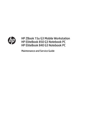
3.2.4 Simultaneous Multithreading (SMT) (1)3.2.4 Simultaneous Multithreading (SMT)In Nehalem Intel re-implemented SMT (since Core 2/Penryn did not support SMT)SMT: two-way multithreading (two threads at the same time)Each issue slot may be filled now from two threads.Benefits A 4-wide core is fed more efficiently (from 2 threads). Hides latency of a single tread. More performance with low (e.g. 5%) additionaldie area cost. May provide significant performance increase ondedicated applications, as seen in the next Figure.Figure 3.2.4.1: Simultaneous Multithreading (SMT) of Nehalem [1]*
3.2.4 Simultaneous Multithreading (SMT) (2)Performance gains achieved by Nehalem’s SMT [1]
3.2.5.1 Introduction (1)3.2.5 Enhanced power management3.2.5.1 IntroductionHaving 4 cores instead of two clearly results in higher power consumption and thisputs greater emphasis on a more sophisticated power management.Innovations introduced to encounter this challenge: Integrated power gates (to significantly reduce power consumption) Integrated Power Control Unit (PCU) (to implement the complex task of power management) Turbo Boost technology (to convert power headroom to higher performance)Above innovations will be discussed while we give a brief introduction into the wide spectrumof power management technics.Power consumption: energia fogyasztásPower management: fogyasztás kezelés/disszipáció kezelésPower gates: áramellátás kapu*
3.2.5.1 Introduction (2)Approaches and key technologies of power management in computersApproaches for the power management of computers(Strongly simplified)Reducing power consumptionat the circuit level(Achieved by circuit design)Clock gatingPM at the platform level(ACPI-based, achieved by system design)PM of the processorPower gating(Nehalem)PM of CPU coresPM of idle CPU coresReducing power consumptionof idle CPU coresC-state management(ACPI-based)PM of active CPU coresReducing thepower consumptionof active CPU coresUtilizing the power headroomof a proc. packageto raise performanceDVFSby means of a PCUTurbo Boost Technology(Nehalem)(Nehalem)*
3.2.5.2 Clock gating (1)3.2.5.2 Clock gating Eliminates dynamic dissipation of unused circuits by switching off their clocking. Clock gating was introduced in the late 1990s e.g. in DEC processor designs(in the Alpha 21264 (1996) for gating the FP unit or the StrongARM SA110 (1996)),designated at that time as conditional clocking. Soon fine-grained clock gating became widely used, e.g. in Intel's Pentium 4 (2000) orPentium M (Banias) (2003). Recently, fine-grained clock-gating is a pervasively used technique in processors.Figure: Principle of clock gating [278]*
3.2.5.3 Power gating (1)3.2.5.3 Power gating [32]Power gating means switching off unused units from the power supply by power transistors.It eliminates both static and dynamic dissipation of unused units.Power switchesIt is a precondition of an efficient Turbo Boost technology, since it eliminates both static anddynamic dissipation of idle cores and thus enlarges notable the power headroom.Power gating: áramellátás kapuzása*
3.2.5.3 Power gating (2)Remark: Introducing power gating by different processor vendorsIntel introduced power gating along with their Nehalem microarchitecture in 2008,subsequently many other processor vendors followed them, as the Table below shows.VendorIntelAMDIBMFamilyYear of intro.Nehalem2008Westmere2010Sandy Bridge2011Ivy Bridge2012Skylake2015Atom families2010 - 2016K12-based LlanoK14-based BobcatK15-based Bulldozer families201120112011 - 2015POWER7 2012POWER8(Iintegrated PG and DVFS)2014Table: Introduction of power gatingPower gating: áramellátás kapuzása
3.2.5.3 Power gating (3)Integrated voltage regulators (FIVR) took over the task of power gatesIntegrated voltage regulators(as introduced in Intel'sHaswell and Broadwell-based lines)allow to switch off units individuallyso they supersede the use of power gating,as the Figure on the right shows.Figure: Use of integrated voltage regulators in Intel's Haswell processor (2014) [279]
3.2.5.3 Power gating (4)Reuse of power gating after Intel has suspended the implementation of integratedvoltage regulators in their Skylake line (2015) Integrated voltage regulators (FIVR), introducedinto the Haswell and Broadwell lines unduly increaseddissipation and thus reduced clock frequency. This is the reason why Intel omitted integratedvoltage regulators in their subsequent Skylake line,as indicated in the Figure on the right.Figure: Reintroducing power gating in Intel'sSkylake line [280]
3.2.5.4 The ACPI standard (1)3.2.5.4 The ACPI standard Power management can efficiently be supported by the OS, since the task scheduler “sees”the utilization of the cores or threads and this “knowledge” can be utilized for powermanagement, as discussed later. OS support requires a standard interface for power management between the processor andthe OS.This need gave birth to power management standards.*
3.2.5.4 The ACPI standard (1b)Evolution of power management standardsPower management standardsIntroducedVendorAdvancedPower Management(APM)10/199001/1992IntelIntel and MicrosoftIntel, Microsoft,Compaq, Phoenix and ToshibaOpen standard i.f.between OS and BIOSOpen standard i.f.between OS and HWA set of PM techniquesTyp. CPU scalingDone basically for CPU: for devices:First proc. supp.First Intel’schipset supp.:OS support:Advanced Configurationand Power Interface(ACPI)(SL technology)SFSby SMMby SMM386SL (embedded)486SL (embedded)486 family (since 06/1993)420EX420ZXNo OS supportneededDFSby OSPM/BIOSby BIOS/OSPM/OS handlersPentium430FX with PIIX430HX/430VX with PIIX3Windows 95 (08/1995)Windows 98 (06/1998)12/1996DVFSby OSPMby OSPMPentium M andsubsequent processors430TX with PIIX4 (ACPI 1.0)Windows 98 (ACPI 1.0) (06/1998)Windows XP SP1 (ACPI 2.0) (02/2002)
3.2.5.4 The ACPI standard (2)Emergence of the ACPI standard and its OS supportConsumerproducts08/199505/1999W 95W 98SEACPI 1.0Introduction of OS support of DVFS02/2000Desktops/Laptops10/2001W 2000 Prof.ACPI 1.0W XPACPI 1.0bSP1 (09/2002): ACPI 2.0102/2000Servers01/200704/2003End of 2009W VistaW7ACPI 3.0ACPI 3.002/2008W 2000 ServerW Server 2003W Server 2008ACPI 1.0ACPI 2.01ACPI 3.007/1996CorporateproductsW NT 4.019951:12/199607/200009/2004ACPI 1.0ACPI 2.0ACPI 3.02000200506/200912/2011ACPI 4.0ACPI 5.02010Windows XP and Windows Server 2003 do not support all of the ACPI 2.0 specification [281]
3.2.5.4 The ACPI standard (3)Support of multicores and multithreading in ACPI 3.0 and its OS supportConsumerproducts08/199505/1999W 95W 98SEACPI 1.002/2000Desktops/LaptopsSupport of multicores and multithreading10/2001W 2000 Prof.ACPI 1.0W XPACPI 1.0bSP1 (09/2002): ACPI 2.0102/2000Servers01/200704/2003End of 2009W VistaW7ACPI 3.0ACPI 3.002/2008W 2000 ServerW Server 2003W Server 2008ACPI 1.0ACPI 2.01ACPI 3.007/1996CorporateproductsW NT 4.019951:12/199607/200009/2004ACPI 1.0ACPI 2.0ACPI 3.02000200506/200912/2011ACPI 4.0ACPI 5.02010Windows XP and Windows Server 2003 do not support all of the ACPI 2.0 specification [281]
3.2.5.4 The ACPI standard (4)Support of hardware controlled performance states (SpeedShift technology) in ACPI 5.0Consumerproducts08/199505/1999W 95W 98SEACPI 1.002/2000Desktops/Laptops10/2001W 2000 Prof.ACPI 1.0W XPACPI 1.0bSP1 (09/2002): ACPI 2.0102/2000Servers01/200704/2003End of 2009W VistaW7ACPI 3.0ACPI 3.002/2008W 2000 ServerW Server 2003W Server 2008ACPI 1.0ACPI 2.01ACPI 3.007/1996Corporateproducts19951:Hardware controlled performance states(Intel Speed Shift technology)W NT 4.012/199607/200009/2004ACPI 1.0ACPI 2.0ACPI 3.02000200506/200912/2011ACPI 4.0ACPI 5.02010Windows XP and Windows Server 2003 do not support all of the ACPI 2.0 specification [281]
3.2.5.4 The ACPI standard (5)Example: ACPI states inHaswell-based mobiles [282]Pi: Performance states(active states, since ACPI 2.0))Ci: Idle states(C4 Cn states since ACPI 2.0)Gi: Global statesSi: System Sleep statesG1: OS-initiated, system context is saved,no rebooting needed.G2/Soft off: OS-initiated shut down.Power supply remains on,system context is not saved,the system must be restarted.G3/Mechanical off: Entered byactivating a mechanical switch.The system must be restarted.*
3.2.5.5 C-state management (1)3.2.5.5 C-state management Idle periods of instruction execution allow to reduce power consumption, e.g. by clock gating,power gating, switching off caches etc. To allow managing idle states by means of OSs in a standardized way, ACPI introduced sog.C-states.*
3.2.5.5 C-state management (2)Introduction to C-states -1 Version 1.0 of the ACPI standard introduced the C1 . C3 idle states in 1996. Additional idle states C4 . .Cn were defined in version 2.0 of this standard in 2000,as indicated in the next Figure. We note that the ACPI standard details the idle states C1 to C3 but does not give a detailedspecification for the C4 .Cn states, thus the C4 and higher states may be specifieddifferently from vendor to vendor and from processor line to processor line.
3.2.5.5 C-state management (3)Example: ACPI states inHaswell-based mobiles [282]Pi: Performance states(active states, since ACPI 2.0))Ci: Idle states(C4 Cn states since ACPI 2.0)Gi: Global statesSi: System Sleep statesG1: OS-initiated, system context is saved,no rebooting needed.G2/Soft off: OS-initiated shut down.Power supply remains on,system context is not saved,the system must be restarted.G3/Mechanical off: Entered byactivating a mechanical switch.The system must be restarted.
3.2.5.5 C-state management (4)Introduction to C-states -2 Higher numbered C-states designate increasingly deeper sleep states. Deeper sleep states provide higher power savings but require higher enter and exit times,as seen in the next Figure.*
3.2.5.5 C-state management (5)Power consumption vs. transfer latency of C-statesHigher numbered C states i.e. deeper idle states, result in lower power consumptionbut cause increasingly longer transit latencies (enter plus exit times), as indicated belowfor the C-states C1 - C6.Power consumptionC0C1C2C3C4C5C6Enter exit latencyFigure: Power consumption vs. transfer latency of C-states
3.2.5.5 C-state management (6)Example: Dissipation and enter exit latencies of idle states in Intel’sPenryn-based Core 2 Duo Mobile processors (e.g. T9xxx) (2008) [283]Dissipation4035WC0: Working30 15 μs for PLLstabilization(after switching on)2012.5WC1: AutoHaltC2: StopGrantNot designated latenciesusually 1 µs 100-200 μs forentering/exitingC611.8WC3: Sleep105.5W5C3: Deep Sleep L1 caches are Stop execution Stop proc. clocking flushed into theL2 cache but service snoops Stop proc. clocking latch interrupts Stop PLL (BCLK)1.7W1.3W0.3WC4: Deeper SleepC5: Enh.Deeper SleepC6: DeepPower Down L2 partially flushed Vcc lowered(until both thecores and theL2 cache retaintheir state)Enter exitlatency(rough estimate) Both coressave their Vcc further loweredarchitectural states(until the coresin on-die SRAMsretain their state) Vcc deep below thecore retention voltage L2 entirely flushed No snnops No latching ofinterrupts C1-C3 Dissipation values in the Highest Frequency Mode), FSB: 800í MT/s
3.2.5.5 C-state management (8)Example: ACPI C-states in Intel’s mobile Penryn-based processors [26]C6 Idle state Intelligentheuristics decideswhen enter into.
3.2.5.5 C-state management (9)Remark While mobile processors are the most sensitive processor class concerning powerconsumption, these processors typically spearhead C-state management. By contrast, desktop and server processors support often only a subset of C-statesprovided by mobiles, e.g. Haswell mobile pro
desktop segment (Core i7-9xx (Bloomfield)) 4C in 11/2008 Core 2 New Microarch. 65 nm Penryn New Process 45 nm Nehalem New Microarch . 45 nm West-mere New Process 32 nm Sandy Bridge Microarch 32 nm Ivy Bridge Process 22 nm Haswell New Microarchi. 22 nm TOCK TICK TOCK TICK TOCK TICK TOCK 1. gen. 2. gen. 3. gen. 4. gen. 5. gen. Broad-well 14 nm TICK