Transcription
Application Note FLASHProgramming TriCoreRelease 02.2022MANUAL
Application Note FLASH Programming TriCoreTRACE32 Online HelpTRACE32 DirectoryTRACE32 IndexTRACE32 Documents . ICD In-Circuit Debugger . Processor Architecture Manuals . TriCore . TriCore Application Notes . Application Note FLASH Programming TriCore .1Introduction .4FLASH Programming Commands .5Organization of TriCore FLASH Scripts .6FLASH Declaration Scripts6FLASH Feature Scripts7FLASH Demo Scripts7TC2xx Devices .11Erased FLASH11TRACE32 Methods for Safe FLASH Programming13NOP Sectors13Protecting Boot Mode Headers14Recommended Procedures15Boot Mode Headers15User Configuration Blocks16HSM18OTP and WOP Sectors21TC3xx Devices .22Erased FLASH22TRACE32 Mechanisms for Safe FLASH Programming24NOP Sectors24Recommended Procedures25User Configuration Blocks25HSM30OTP and WOP Sectors33DFLASH Single-Ended and Complement Sensing Mode34Support for SOTA35 1989-2022 LauterbachApplication Note FLASH Programming TriCore 2
FLASH Programming with SWAP Enabled35The SWAP Feature Script36 1989-2022 LauterbachApplication Note FLASH Programming TriCore 3
Application Note FLASH Programming TriCoreVersion 09-Mar-2022IntroductionTriCore AURIX devices have many configurations that are located in FLASH (e.g., User ConfigurationsBlocks). For security and safety reasons, the chip offers the possibility, e.g., to install intended locking of thedebug access, or prohibit programming of specific FLASH sectors. But programming invalid content to theFLASH may result in locking the device forever.TRACE32 provides several methods to minimize the risks of accidentally writing wrong content to FLASHand consequently locking the device without recovering possibilities. To fully benefit from these mechanisms,it is mandatory to understand the TRACE32 FLASH programming strategies for TriCore AURIX devices andto learn about recommended procedures and good practices when writing FLASH scripts. This is theintention of this document.This document is only discussing peculiarities of TRACE32 internal FLASH programming for TriCore AURIXdevices. The document “Onchip/NOR FLASH Programming User’s Guide” (norflash.pdf) coversTRACE32 internal FLASH programming in general and is recommended as basic knowledge for thisapplication note.The first section summarizes the TRACE32 FLASH programming commands and which methods have tobe used or avoided according to the TriCore specificities. The second section presents different types ofTRACE32 FLASH scripts for TriCore, their location in the TRACE32 installation and their intended usage.The last two sections are separately covering FLASH programming for TC2xx and TC3xx. Chip specificbehaviors, protection mechanisms, practical use-cases and scripting examples are provided.In this document, the term AURIX is used to designate all TC2xx and TC3xx devices.The procedures and scripts presented in this document are designed to avoidcommon risks and mistakes resulting in a locked device. TRACE32 FLASHscripts consider critical content as valid when it passes number of formalchecks. Formal checks are, e.g., correct address alignment, presence of magicpatterns matching CRCs, etc. When formal checks have passed, the StartupSoftware (SSW) will consider the content as valid and will evaluate it.The TRACE32 FLASH scripts are continuously improved and extended to covera maximum of protection but there is no guarantee that all cases are covered.For example, the scripts may not warn if a user actively enables locking.In no case using TRACE32 FLASH scripts will replace reading the TriCore UserManuals and Errata Sheets. 1989-2022 LauterbachApplication Note FLASH Programming TriCore 4
FLASH Programming CommandsTRACE32 offers three FLASH programming methods. Each method uses different groups of FLASHprogramming commands: FLASH.Erase / FLASH.Program FLASH.ReProgram FLASH.AUTODetails on how these commands work and information about their parameters and option are explained in“Onchip/NOR FLASH Programming User’s Guide” (norflash.pdf).For TriCore, the commands FLASH.Erase and FLASH.Program have to be used with care. Using thesecommands might result in incorrect ECC and erroneous FLASH content. This especially happens when theprogrammed file format fragmentation does not cover the entire ECC line.The command FLASH.ReProgram is the convenient choice when programming a content that will make bigchanges to many FLASH sectors. Loading an application ELF file is a typical example.The command FLASH.AUTO is the best fit when making small patches or changing some bytes in theFLASH. 1989-2022 LauterbachApplication Note FLASH Programming TriCore 5
Organization of TriCore FLASH ScriptsThree categories of FLASH scripts for the TriCore architecture are available in the TRACE32 installation: FLASH declaration scripts FLASH feature scripts FLASH demo scriptsThis section presents their organization and intended usage for writing user’s FLASH scripts.FLASH Declaration ScriptsInternal FLASH programming for AURIX devices is using a target-controlled method, where the FLASHprogramming algorithm (or FLASH driver) is executed from the device RAM under control of TRACE32PowerView. Every AURIX device has a different FLASH structure and consequently a different FLASHmapping. Thus it is necessary to specify the FLASH mapping before the FLASH programming commandscan be used.The FLASH mapping declaration is done via the TRACE32 FLASH declaration scripts located in theinstallation directory under “ /demo/tricore/flash”. Each device series has a FLASH declarationscript. For example, the script tc39x.cmm is intended to be used for all TC39x devices. Obviously, the scripttc27x.cmm is for all TC27x devices.The FLASH declaration scripts are intended as “library” scripts and have to be used as-is. Those scriptsmust not be modified or partly copied to the user’s FLASH scripts. Instead, they have to be called from theuser’s FLASH scripts with the appropriate arguments.Example:DO /demo/tricore/flash/tc39x.cmm CPU TC397XE PREPAREONLY DUALPORT 1The “PREPAREONLY” argument instructs the FLASH declaration script to declare the FLASH and exitwithout FLASH programming.The argument “CPU cpu ” selects the used CPU derivative. This argument is optional if the debugger totarget communication is already established.The argument “DUALPORT 1” enables data transfer via dual-port memory access and ensures acontinuous running of the FLASH algorithm until the FLASH programming is finished. This results in a higherFLASH programming performance.Other important information and details about all the script arguments can be found in the script header.Some devices, using the same CPU selection, might be available with different FLASH sizes andconsequently require different FLASH declarations. This is handled transparently if the device is alreadysupported by the used FLASH declaration script version. A TRACE32 software update can be requested 1989-2022 LauterbachApplication Note FLASH Programming TriCore 6
from support@lauterbach.com if the device is not supported by the used TRACE32 software version (i.e.the CPU selection is missing) and/or by the FLASH declaration script (an error “Unsupported Pflash Size”is thrown by the script).NOTE:Do not move the FLASH declaration scripts from their default location. This leads toproblems when performing a TRACE32 software update, since the copied scriptswon’t be updated to the newest version. This prevents to benefit from eventualscript improvements and support of new devices.FLASH Feature ScriptsLike FLASH declaration scripts, FLASH feature scripts are located in the installation directory under“ /demo/tricore/flash”. They have to be used as-is by calling them from the user’s FLASH scriptsusing appropriate arguments.The feature scripts are used to help programming various features including checks for valid content.Examples of FLASH feature scripts for TC2xx: tc2xx-ucb.cmm tc2xx-bmhd.cmm tc2xx-hsm-config.cmm tc23x-hsm.cmm, tc27x-hsm.cmm, tc29x-hsm.cmmExamples of FLASH feature scripts for TC3xx: tc3xx-ucb.cmm tc3xx-hsm-config.cmm tc3xx-swap.cmmDetails about the scripts’ arguments and intended usage are documented in the script headers. Use-casesand examples will be detailed later in this document.FLASH Demo ScriptsThe TRACE32 demo directory for the TriCore architecture includes FLASH demo scripts for Infineonreference boards. These demo scripts are located in the installation under“ /demo/tricore/hardware” and are organized by board name and chip derivative.Example:PEDIT /demo/tricore/hardware/triboard-tc3x7/tc387qp/demo flash.cmm 1989-2022 LauterbachApplication Note FLASH Programming TriCore 7
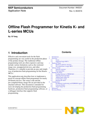
These scripts are intended to be copied and used as templates to create customised users’ scripts.TRACE32 script search dialog can be used to search an appropriate FLASH demo script. The dialog can beopened from the menu “Help - Demo Scripts.”. Using the chip name and appropriate keywords to refinethe search, the matching scripts from the TRACE32 installation are listed.In this example, the matching FLASH demo script is entitled “Demo script for TC387QP on TriBoardTC3x7 (Flash, sieve app)”. By selecting the script, a more detailed description is displayed.The FLASH demo scripts have a unified layout with three main parts.The first part of the script initiates the debugger/target communication. This includes setting the CPUselection and setting up all the required configurations to start the debugger/target communicationsuccessfully. 1989-2022 LauterbachApplication Note FLASH Programming TriCore 8
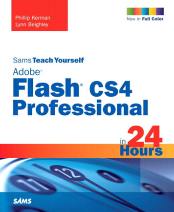
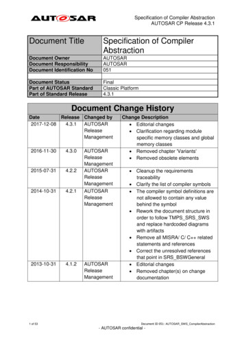
Before starting the FLASH programming, it is very important to disable all external (and internal) watchdogsto avoid resetting the target while the FLASH programming is in progress. It is also very important to startFLASH programming from a “clean” known state of the target. In this example, the command SYStem.Up isused to reset the target and halt the CPU at the reset vector.After a successful startup of the debugger/target communication, the state “system ready” is displayed inthe status bar.The second part is the FLASH preparation. This is done by calling the FLASH declaration script with the“PREPAREONLY” argument.DO /demo/tricore/flash/tc38x.cmm CPU TC387QP PREPAREONLYAfter the FLASH preparation the command FLASH.List can be used to examine the declared FLASHmapping. 1989-2022 LauterbachApplication Note FLASH Programming TriCore 9
The third part of a FLASH demo script is the FLASH programming. The command FLASH.ReProgram ALLenables the FLASH programming for all “TARGET” sectors, then the ELF file of the demo application (orany other binary format) is loaded using the appropriate Data.LOAD command.After executing FLASH.ReProgram OFF the effective FLASH programming to the device is started.The rest of this demo script shows the FLASH programming of the BMHDs. This part will be detailed in thefollowing sections. 1989-2022 LauterbachApplication Note FLASH Programming TriCore 10
TC2xx DevicesErased FLASHFor TriCore AURIX devices the data is stored in FLASH with error correcting codes “ECC” in order to protectagainst data corruption. These ECC can correct a certain amount of bit errors.For PFLASH, the ECC are calculated over the data and the address bits. After an erase, the state of the dataas well as the state of the ECC is “all-0”. As the ECC of 0x0 is not 0x0, the stored ECC does not match withthe ECC of the actual data. Thus, an erased PFLASH range is resulting in ECC errors.The ECC is automatically evaluated by the chip when reading data. Thus, reading from an erased PFLASHsector returns “bus error” indicated as “?” in, e.g., a Data.dump window.For DFLASH, a different ECC algorithm is used. ECC are calculated over the data bits only and the “all-0”state for data and checksums do not result in “bus errors” when reading from erased DFLASH sectors.Bus errors that are caused by uncorrectable ECC errors can be disabled by configuringFLASH0 MARP.TRAPDIS and FLASH0 MARD.TRAPDIS register fields.After changing the configuration of FLASH0 MARP.TRAPDIS field to disable the uncorrectable ECC errorreporting, the erased range is displayed like in the following screenshot.Some bits still show the value 1. The displayed values don’t reflect the real physical FLASH content, but thisreflects the content obtained after applying the ECC correction. The result is not the same for all thePFLASH lines because for PFLASH, the address of the ECC line is used for calculating the ECC. 1989-2022 LauterbachApplication Note FLASH Programming TriCore 11
The real PFLASH content can be displayed by additionally disabling the ECC correction in thecorresponding PFLASH register filed FLASH0 ECCRPp.ECCORDIS like the example in the followingscreenshot.NOTE:Configuring FLASH0 MARP and FLASH0 MARD to mask the bus error traps ordisabling the ECC correction in FLASH0 ECCRPp are not presented here asprogramming options. These are only mentioned for better understanding of thechip behavior.To ensure that all PFLASH and ECCs are initialized, the command FLASH.ReProgram can be used withthe option “/FILL” to fill all erase sectors with 0.Example:FLASH.ReProgram ALL /Erase /FILLData.LOAD.Elf application.elfFLASH.ReProgram OFF 1989-2022 LauterbachApplication Note FLASH Programming TriCore 12
TRACE32 Methods for Safe FLASH ProgrammingNOP SectorsTRACE32 FLASH declaration scripts declare sensitive sectors as “NOP” to protect them against unwantedFLASH programming. TRACE32 PowerView silently discards all erase and write operations to “NOP”sectors.When it is required to make changes to “NOP” sectors, the command FLASH.CHANGEtype has to beused to modify the FLASH sector type to “TARGET”. Only then, FLASH operations for that range areperformed by TRACE32 PowerView.FLASH sectors that are declared by TRACE32 FLASH scripts as “NOP” needto be handled with special care. Before making any changes to these sectors, itis mandatory to read the Infineon documentation for understanding the effectsof the modifications.To prevent unintended bricking of the device the FLASH declaration scripts for TC2xx declare the tuningprotection configurations and the HSM code as “NOP” sectors. The following is an extract from tc27x.cmmFLASH declaration script.FLASH.Create 1. 0xA0014000 0x3FFF 0x4000 NOP Long /INFO "Tuning Protec."FLASH.Create 1. 0xA0018000 0x3FFF 0x4000 NOP Long /INFO "HSM code sect."These sectors can safely be used for the application if the user makes sure that the code he is programmingwill not lock the device.The FLASH programming scripts for TC2xx does not provide checks to ensure that the code programmed tothe tuning protection sectors or HSM code sectors is safe. For the tuning protection sectors, the user has toensure this by himself. For the HSM code sectors it is strongly recommended to use the checks provided bythe HSM feature scripts e.g. tc29x-hsm.cmm. Details and scripting examples are provided in therecommended procedures paragraph for HSM.NOTE: 1989-2022 LauterbachIt is strongly recommended to use the command FLASH.CHANGEtype tochange a sector from “NOP” to “TARGET”. After programming, change thesector back to “NOP” to avoid unintended programming with invalid content.Application Note FLASH Programming TriCore 13
Protecting Boot Mode HeadersFor TC2xx devices, the option “/BootModeHeaDer” is used with the command FLASH.Create to makeTRACE32 PowerView aware of the boot mode header regions. TRACE32 will then ensure that the oldcontent of the boot mode headers will be preserved if nothing is programmed to them after an erase.Example:&s0 s2 "0xA0000000--0xA000BFFF"; PS0, S0.S2&bmhd0 "0xA0000000--0xA000001F"; Range of BMHD0FLASH.Create 1. &s0 s2 0x4000 TARGET Long /BootModeHeaDer &bmhd0The resulting FLASH declaration can be viewed using the command FLASH.List. The following FLASHdeclaration is obtained after executing the FLASH declaration script for TC277TF device using theparameter “PREPAREONLY”.DO /demo/tricore/flash/tc27x.cmm CPU TC277TF PREPAREONLY 1989-2022 LauterbachApplication Note FLASH Programming TriCore 14
Recommended ProceduresIn order to prevent unwanted locking of a device the following procedures must be followed. They combinethe FLASH declaration script and the FLASH feature scripts.Boot Mode HeadersWhen booting an AURIX device, at least one boot mode header should contain valid data. For some earlyTC2xx devices, having no valid boot mode header is fatal. This will lock the device with no recoveringpossibilities.The FLASH declaration scripts can be used to check if at least one valid Boot Mode Header is going to beprogrammed to the device. The script needs to be called using the argument “CHECKBMHD”.Example:DO /demo/tricore/flash/tc27x.cmm CHECKBMHDThis check has to be performed before the effective FLASH programming is started via the commandFLASH.ReProgram OFF.If at least one valid boot mode header is found, the script execution returns the result “BMHD OK”. Thenthe user script can continue the FLASH programming.If no valid boot mode header is found, the check will return “BMHD MISSING” and the user script mustabort the FLASH programming.Here is the script example with the full programming flow:; Enable FLASH programmingFLASH.ReProgram ALL; Load the demo applicationData.LOAD.Elf application.elf; Check if there is at least one valid BMHDDO /demo/tricore/flash/tc27x.cmm CHECKBMHDENTRY &bmhdResultIF ("&bmhdResult" "BMHD OK")(; At least one valid BMHD is detected make the changes to the deviceFLASH.ReProgram OFF)ELSE(DIALOG.OK "No valid Boot Mode Header found!" "Reverting loaded data"FLASH.ReProgram CANCELENDDO) 1989-2022 LauterbachApplication Note FLASH Programming TriCore 15
User Configuration BlocksThe FLASH feature script tc2xx-ucb.cmm is used to help programming UCBs and test for valid content.The following example shows how the PFLASH UCB can be programmed when it is in a confirmed state(indicated by the register field FPRO.PROINP). The main steps to achieve this are the following:1.Perform the FLASH declaration using the appropriate FLASH declaration script.2.Activate UCB PFLASH programming by calling the UCB programming script using the argument“ACTIVATE”. This combines the following steps:-Unlocking the UCB PFLASH password protection. This is only required if UCB PFLASHpassword protection is active.-Changing the UCB PFLASH sector type from “NOP” to “TARGET” to allow FLASHprogramming by TRACE32 PowerView.-Enabling FLASH programming for UCB PFLASH using FLASH.AUTO command. The latter isused to preserve the unchanged content of the affected FLASH sector.Unlocking the UCB password protection requires the unlock password to be provided. This isachieved by additionally providing the argument “PWD password ” like in the following example:&pwd "0x0 0x1 0x2 0x3 0x4 0x5 0x6 0x7"DO /demo/tricore/flash/tc2xx-ucb.cmm UCB PFLASH ACTIVATE PWD &pwdAlternatively, a dialog can be used to enter the password manually. This is done by using theargument “DIALOG” instead of “PWD password ”.3.Make the desired changes to the UCB via, e.g., Data.Set commands for both original and copyUCB contents.4.Program the modifications by calling the UCB programming script using the argument“PROGRAM”. This will perform the following:-Do a formal verification of the UCB PFLASH content.-If the provided content is formally correct the changes are programmed to the device and thescript returns “UCBOK”.-If the formal checks detected invalid content the FLASH programming is aborted and thescript returns the result “UCBFAIL”.In both cases the NOP protection of UCB PFLASH sector is restored. 1989-2022 LauterbachApplication Note FLASH Programming TriCore 16
Here is the script example with the full programming flow:; Perform the FLASH declarationDO /demo/tricore/flash/tc27x.cmm PREPAREONLY CPU TC277TF; Activate UCB modification:; - Unlock password protection to allow programming of UCB PFLASH; - Allow FLASH programming by changing the sector type from NOP to;TARGET; - Enable FLASH programming for UCB PFLASH using FLASH.AUTO commandDO /demo/tricore/flash/tc2xx-ucb.cmm UCB PFLASH ACTIVATE DIALOG; Disable all write protections in PROCONP0 original and copy contentData.Set 0xAF100000 %Long 0x0Data.Set 0xAF100010 %Long 0x0; Program the modifications:; - Formal verification of the UCB PFLASH content; - The content is formally correct Program the changes to the device; - The check detected invalid content Abort FLASH programming; - In any case restore NOP protection for UCB PFLASH rangeDO /demo/tricore/flash/tc2xx-ucb.cmm UCB PFLASH PROGRAMENTRY &resultIF ("&result" "UCBOK")(PRINT "UCB PFLASH programming successful") 1989-2022 LauterbachApplication Note FLASH Programming TriCore 17
HSMEnabling HSM boot when no valid HSM code is present will lock the device permanently. Series-specificHSM FLASH scripts can be used to program with maximum safety.Example 1:This example shows how the following HSM feature scripts can be used to check for valid HSM code andenable the HSM boot. tc23x-hsm.cmm tc27x-hsm.cmm tc29x-hsm.cmmAssuming that the TriCore application is already programmed to the device, the recommended FLASHprogramming flow for HSM programming is the following:1.Disable NOP protection of HSM code and configuration sectors:Per default, the FLASH declaration scripts declare HSM code sectors as “NOP”. It is necessary tochange these sectors types to “TARGET” to allow their programming by TRACE32 PowerView. HSMFLASH scripts can be used to achieve this using the script argument “PREPAREONLY”.DO /demo/tricore/flash/tc27x-hsm.cmm CPU TC277TF PREPAREONLY2.Program the HSM application code:The FLASH programming of HSM application can be done via, e.g., HSM specific ELF file or anyother binary format. The FLASH programming commands FLASH.ReProgram have to be used.FLASH.ReProgram ALLData.LOAD.Elf hsm app.elf /NoClear /NoRegister /NosYmbolFLASH.ReProgram OFF3.Check for valid HSM code and enable HSM boot:After programming the HSM code, a post programming check could be done to verify if theapplication is correctly programmed to the target FLASH using the command Data.LOAD with theoption “/DIFF”.If any difference is found, HSM boot needs to be disabled by calling the HSM FLASH script with theargument “DISABLE”. 1989-2022 LauterbachApplication Note FLASH Programming TriCore 18
If the HSM application file is correctly programmed the HSM FLASH script can safely be called withthe argument “ENABLE”. This will verify if the HSM programmed boot vectors are valid and enableHSM by programming the register UCB HSMCOTP. Otherwise, the HSM is kept disabled.Data.LOAD.Elf hsm app.elf /NoClear /NoRegister /NosYmbol /DIFFIF FOUND()(; Ensure that HSM is kept disabled to avoid locking the device!DO /demo/tricore/flash/tc27x-hsm.cmm DISABLEENDDO)ELSE(; Check HSM code area and enable HSMDO /demo/tricore/flash/tc27x-hsm.cmm ENABLE)4.Restore the NOP protection of HSM code and configuration sectors: After HSM FLASHprogramming is finished, restore the NOP protection of HSM sectors by calling the HSM FLASHscript using the argument “FINISH”.DO /demo/tricore/flash/tc27x-hsm.cmm FINISHHere is the script example with the full programming flow:DO /demo/tricore/flash/tc27x-hsm.cmm CPU TC277TF PREPAREONLYFLASH.ReProgram ALLData.LOAD.Elf hsm app.elf /NoClear /NoRegister /NosYmbolFLASH.ReProgram OFF; Check the HSM Elf file is correctly programmed to the deviceData.LOAD.Elf hsm app.elf /NoClear /NoRegister /NosYmbol /DIFFIF FOUND()(; Ensure that HSM is kept disabled to avoid locking the device!DO /demo/tricore/flash/tc27x-hsm.cmm DISABLEENDDO)ELSE(; Check HSM code area and enable HSMDO /demo/tricore/flash/tc27x-hsm.cmm ENABLE)DO /demo/tricore/flash/tc27x-hsm.cmm FINISH 1989-2022 LauterbachApplication Note FLASH Programming TriCore 19
Example 2:This example shows how the HSM feature script tc2xx-hsm-config.cmm can be used for an easierconfiguration of the HSM related chip setting.The script can be started in dialog mode as follows.DO /demo/tricore/flash/tc2xx-hsm-config.cmmThe HSM related setups are configured via various check-boxes. The “Refresh” button reloads thecurrently programmed configuration. After selecting the desired HSM configurations the button “Program”stores the new configuration to the device. If the selected setup enables the HSM boot, the script will firstcheck if the HSM boot vectors are valid, otherwise the FLASH programming is aborted to preventpermanent locking of the device.The button “Show” generates a script snippet with all the settings to be made, that can be copied to theuser’s FLASH script. 1989-2022 LauterbachApplication Note FLASH Programming TriCore 20
OTP and WOP SectorsFor TriCore AURIX devices, beside write protection with password, two types of sector specific programmingprotection can be distinguished. FLASH sectors that are configured with OTP (One-Time Programmable) protection can not beerased or programmed. Otherwise, FLASH programming errors will be reported by the hardware. FLASH sectors that are configured with WOP (Write-page Once Protection) can be programmedonce. These sectors can only be programmed if they are in erased state. Erasing these sectors isprevented by hardware after the protection is activated. The hardware will report an error whentrying to erase them.TRACE32 defines the FLASH sectors that must not be erased or programmed as “NOP” sectors. ThusOTP protected sectors (as defined by Infineon) are declared by TRACE32 FLASH declaration scripts asNOP sectors.TRACE32 uses the “OTP” term to designate FLASH sectors that can be programmed once because eraseis prohibited. Thus, the FLASH sectors that are protected with WOP (as defined by Infineon) are declared byTRACE32 FLASH declaration scripts using the option “/OTP”.Sectors declared with “/OTP” can only be programmed with the command FLASH.Program and the option“/OTP” must be specified.Example:FLASH.Program 0xA0000000 0x3FFF /OTPData.Set .FLASH.Program OFFMore details about FLASH programming of TRACE32 OTP sectors can be found in “Onchip/NOR FLASHProgramming User’s Guide” (norflash.pdf). 1989-2022 LauterbachApplication Note FLASH Programming TriCore 21
TC3xx DevicesErased FLASHFor TriCore AURIX devices the data is stored in FLASH with error correcting codes “ECC” in order to protectagainst data corruption. These ECC can correct a certain amount of bit errors.For PFLASH, the ECCs are calculated over the data and the address bits. After an erase, the state of thedata as well as the state of the ECC is “all-0”. As the ECC of 0x0 is not 0x0, the stored ECC does notmatch with the ECC of the actual data. Thus, an erased PFLASH range is resulting in ECC errors.The ECC is automatically evaluated by the chip when reading data. Thus, reading from an erased PFLASHsector returns “bus error” indicated as “?” in, e.g., a Data.dump window.For DFLASH, a different ECC algorithm is used. ECC are calculated over the data bits only and the “all-0”state for data and checksums do not result in “bus errors” when reading from erased DFLASH sectors.Bus errors that are caused by uncorrectable ECC errors can be masked by changing the register fieldFLASHCON1.MASKUECC of the CPU associated to the corresponding PFLASH unit.After changing the configuration in the CPU0 register field FLASHCON1.MASKUECC for disabling the ECCerror reporting, the erased range is displayed like in the following screenshot.Some bits still show the value 1. The displayed values don’t reflect the real physical FLASH content, but thisreflects the content obtained after applying the ECC correction. The result is not the same for all the FLASHcells because the ECC is calculated from the data values and the corresponding address.The real erased FLASH content can be displayed by additionally disabling the ECC correction inFLASHCON2.ECCCORDIS like in the following screenshot. 1989-2022 LauterbachApplication Note FLASH Programming TriCore 22
NOTE:Configuring FLASHCON1 to mask the bus error traps or disabling the ECCcorrection in FLASHCON2 are not presented here as programming options.These are only mentioned for better understanding of the chip behavior.To ensure that all PFLASH and ECCs are initialized, the command FLASH.ReProgram can be used withthe option “/FILL” to fill all erase sectors with 0.Example:FLASH.ReProgram ALL /Erase /FILLData.LOAD.Elf application.elfFLASH.ReProgram OFF 1989-2022 LauterbachApplication Note FLASH Programming TriCore 23
TRACE32 Mechanisms for Safe FLASH ProgrammingNOP SectorsTRACE32 FLASH declaration scripts declare sensitive sectors as “NOP” to protect them against unwantedFLASH programming. TRACE32 PowerView silently discards all erase and write operations to “NOP”sectors.When it is required to make changes to “NOP” sectors, th
1989-2022 Lau terbach Application Note FLASH Programming TriCore 4 Application Note FLASH Programming TriCore Version 09-Mar-2022 Introduction TriCore AURIX devices have many configurations that are located in FLASH (e.g., User Configurations Blocks). For security and safety reasons, the chip offers the possibility, e.g., to install .