Transcription
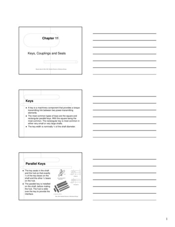
Chapter 11Keys, Couplings and SealsMaterial taken for Mott, 2003, Machine Elements in Mechanical DesignKeyszzzA key is a machinery component that provides a torquetransmitting link between two power-transmittingelements.The most common types of keys are the square andrectangular parallel keys. With the square being themost common. The rectangular key is most common ineither very small or very large shafts.The key width is nominally ¼ of the shaft diameter.Parallel KeyszzThe key seats in the shaftand the hub so that exactly½ of the key bears on theshaft and the other ½ bearson the hub.The parallel key is installedon the shaft, before matingthe hub. The hub is slideover the key to provide theinterface.Mott, 2003, Machine Elements in Mechanical Design1
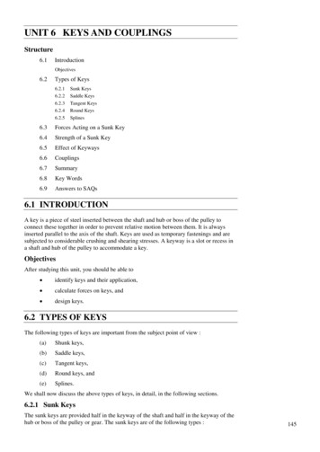
Key Shaft vs. Shaft DiameterMott, 2003, Machine Elements in Mechanical DesignDimensions for FabricationzzKeys are usually cutwith a end-mill orcircular-mill cuttersand leave squarecorners which createstress concentrations.Radiused keyseatsand chamfered keyscan reduce stressconcentrations.Mott, 2003, Machine Elements in Mechanical DesignKey TypeszzTapered keys areinstalled after matingthe hub and shaft.The taper extendsover the length ofthe hub.Pin keys reducestress concentration,but requires a tightfit.Mott, 2003, Machine Elements in Mechanical Design2
Woodruff KeysMott, 2003, Machine Elements in Mechanical DesignUsed in light loading applications, where it is desirableto easy assembly and dis-assembly.zSelection of KeyzzThe type and size of the key is usually selected after theshaft and hub have been designed.The length and material specification is determinedthrough by design analysis, while two factors limit theirselection:––zzWidth of the hubDistance to adjacent stress concentrations.Key is held in place by; set screws, shoulders, retainingrings, or spacers.Keys are commonly made of low-carbon, cold-drawn steel;such as AISI 1020CD with 61 ksi, ultimate strength.Stress AnalysiszThere are two basic failure modes for keystransmitting power.––Shear across the shaft/hub interfaceCompression failure due to bearing stress betweenkey and shaft, or hub.3
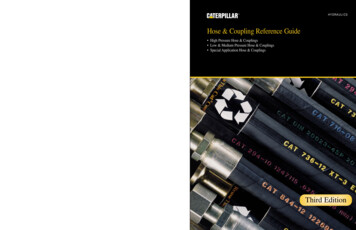
Shear Stress AnalysisMott, 2003, Machine Elements in Mechanical DesignzzThe torque in the shaft creates a force on the lower leftside of the key which in turn creates a reaction forceon the upper right side of the key, transmitting thetorque into the hub.This force couple places the key in shear over thesurface A W*L, where F T / (D/2)Shear Stress AnalysiszShearing stressτ FAszDesign stresszKey Lengthτd T2T ( D / 2)(WL) DWL 0.5 s y / NL τ2TDWdBearing Stress AnalysiszzFailure in bearing is due to compressive stressthat acts of shaft or hub area: L * (H/2), wherefailure occurs on the surface with the lowestcompressive yield strength.Design Stressσzd sy / NN 3 is typical4
Bearing Stress Analysis, cont.zActual compressive stressσ FAcz4TT ( D / 2)( L)( H / 2) DLHSolving of required length using design stressL z 4TN4T DW s y σ d DHUsing Sy from material of lesser yield compressivestrength, be it the key, shaft or hub.Parallel-Square Key DesignzzzzzzComplete shaft design and spec. shaft diameter.Select key size, using W H if shaft size 6.5”.Spec. material, usually AISI 1020 CDDetermine yield strength of key, shaft and hub.Check design based on shear stresses in key,and bearing stresses on material with lessercompressive yield strength.Complete design details of keyseat and key forfabrication.Mott, 2003, Machine Elements in Mechanical Design5
ExampleSplineszzA spline can be described as a series of axialkeys machined into a shaft, with correspondinggrooves machined into the bore of the matingpart (gear, sheave, sprocket, etc).The splines perform the same function as akey in transmitting torque from the shaft to themating element.Splines con’tzThere are many advantages of splines over keys.–zzBecause 4 or more splines are used, as comparedwith 1 or 2 keys, a more uniform transfer of torqueand a lower loading on a given part of the shaft/hubinterface result.The splines are integral with the shaft, so norelative motion can occur as between a key andthe shaft.Because of the multiple splines on the shaft, themating element can be indexed to variouspositions.6
Splines con’tzzSplines can either be straight-sided or involute.The involute form is preferred because itprovides for self-centering of the matingelement and because it can be machined withstandard hobs used to cut gears.Straight-Sided SplineszStraight splinesare madeaccording to thespecifications ofthe SAE andusually contain 4,6, 10, or 16splines.Mott, 2003, Machine Elements in Mechanical DesignMott, 2003, Machine Elements in Mechanical Design7
Straight-Sided Splines con’tzThe torque capacity for SAE splines is basedon the limit of 1000-psi bearing stress on thesides of the splines, from which this formula isderived:––––T 1000NRhWhere N number of splinesR mean radius of the splinesh depth of the splinesStraight-Sided Splines con’tzThe torque capacity is per inch of length of thespline.1 D dD dR [ ] 2 2 241h (D d)2Straight-Sided Splines con’tzThen,T 1000NzD2 d 2(D d) (D d) 1000N428This equation can be further refined for each ofthe types of splines by substitution of theappropriate relationships for N and d.8
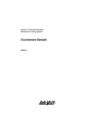
Straight-Sided Splines con’tzzFor example, for the 6-spline version and the Bfit, N 6, d 0.850D, and d2 0.7225D2.Then,22T 1000 * 6zD 0.7225D 208D28Therefore, the required diameter to transmit agiven torque would be D T / 208Straight-Sided Splines con’tzzUse the same approach to find the torquecapacities and required diameters for theother versions of straight splines.The next slide enables an acceptablediameter to be chosen for a spline to carry agiven torque, depending on the desired fit,A, B, or C.Torque Capacity Per Inch of SplineLengthMott, 2003, Machine Elements in Mechanical Design9
Torque Capacity for Straight SplinesMott, 2003, Machine Elements in Mechanical DesignInvolute SplineszzInvolute splines typically made with pressureangles of 30o, 37.5o, or 45o.The major diameter fit produces accurateconcentricity between the shaft and themating element.Involute Splines, con’tzIn the side fit,contact occursonly on thesides of theteeth, but theinvolute formtends to centerthe shaft in themating splinedhub.Mott, 2003, Machine Elements in Mechanical Design10
PinningzzzWith the element in position on the shaft, ahole can be drilled through both the hub andthe shaft, and a pin can be inserted in the hole.The straight, solid, cylindrical pin is subjectedto shear over two cross sections.If there is a force, F, on each end of the pin atthe shaft/hub interface, and if the shaftdiameter is D, then:–T 2F (D /2) FDPinning con’tMott, 2003, Machine Elements in Mechanical DesignPinning con’tzWith the symbol d representing the pindiameter, the shear stress in the pin is:τ zFT4T As D( πd 2 / 4) D( πd 2)Letting the shear stress equal the design stressin shear as before,d 4TD( π)( τd )11
Pinning con’tzSometimes the diameter of the pin is purposelymade small to ensure that the pin will break if amoderate overload is encountered, in order toprotect critical parts of a mechanism.zOne problem with cylindrical pins is that fittingthem adequately to provide precise location ofthe hub and to prevent the pin from falling outis difficult.–Such a pin is called a shear pin.Pinning con’tzThe taper pin overcomes some of these problems, asdoes the split spring pin.Mott, 2003, Machine Elements in Mechanical DesignKeyless Hub to Shaft ConnectionszzUsing a steel ring compressed tightly around asmooth shaft allows torque to be transmittedbetween the hub of a power-transmittingelement and a shaft without having a keybetween the tow elements.The Locking AssemblyTM employees steelrings with opposing mating tapers heldtogether with a series of fasteners.12
Locking AssembliesMott, 2003, Machine Elements in Mechanical DesignKeyless Hub to Shaft ConnectionszWith the Locking AssemblyTM placedcompletely within a counter bore of the hub ofvirtually any kind of power-transmitting elementsuch as a gear, sprocket, fan wheel, cam,coupling, or turbine rotor, the fasteners can betightened to achieve an excellent torquecarrying interface.Split Taper BushingzzzA split taper bushing uses a key to transmittorque.Axial location on the shaft is provided by theclamping action of a split bushing having asmall taper on its outer surface.When the bushing is pulled into a mating hubwith a set of cap screws, the bushing isbrought into tight contact with the shaft to holdthe assembly in the proper axial position.13
Split Taper BushingMott, 2003, Machine Elements in Mechanical DesignSet ScrewszzzA set screw is a threaded fastener drivenradially through a hub to bear on the outersurface of a shaft.The point of the set screw is flat, oval, coneshaped, cupped, or any of several proprietaryforms.The point bears on the shaft or digs slightly intoits surface.Set ScrewsMott, 2003, Machine Elements in Mechanical Design14
Set Screws con’tzzThe set screw transmits torque by the frictionbetween the point and the shaft or by theresistance of the material in shear.The capacity for torque transmission issomewhat variable, depending on thehardness of the shaft material and theclamping force created when the screw isinstalled.Mott, 2003, Machine Elements in Mechanical DesignCouplingszzThe term coupling refers to a device used toconnect two shafts together at their ends forthe purpose of transmitting power.There are two general types of couplings: rigidand flexible.15
Rigid CouplingszzzRigid couplings are designed to draw twoshafts together tightly so that no relative motioncan occur between them.This design is desirable for certain kinds ofequipment in which precise alignment of twoshafts is required and can be provided.In such cases, the coupling must be designedto be capable of transmitting the torque in theshafts.Rigid Couplings con’tzThe load path is from the driving shaft to its flange,through the bolts, into the mating flange, and out to thedriven shaft. The torque places the bolts in shear.Mott, 2003, Machine Elements in Mechanical DesignRigid Couplings con’tzThe total shear force on the bolts depends onthe radius of the bolt circle, Dbc / 2, and thetorque, T.zLetting N be the number of bolts, the shearstress in each bolt is:–F T / (Dbc / 2) 2T / Dbcτ FF2T A s N (π d 2 / 4 ) D bc N (π d 2 / 4 )16
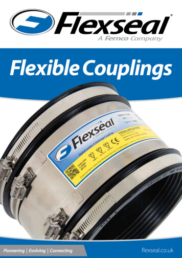
Rigid Couplings con’tzLetting the stress be equal the design stress inshear and solving for the bolt diameter:d 8TDbcN( πτd )Rigid Couplings con’tzzRigid couplings should be used only when thealignment of the two shafts can be maintainedvery accurately, not only at the time ofinstallation but also during operation of themachines.If significant angular, radial, or axialmisalignment occurs, stresses that are difficultto predict and that may lead to early failure dueto fatigue will be induced in the shafts.Flexible CouplingszzzFlexible couplings are designed to transmittorque smoothly while permitting some axial,radial, and angular misalignment.The flexibility is such that when misalignmentdoes occur, parts of the coupling move withlittle or no resistance.Thus, no significant axial or bending stressesare developed in the shaft.17
Mott, 2003, Machine Elements in Mechanical DesignMott, 2003, Machine Elements in Mechanical DesignMott, 2003, Machine Elements in Mechanical Design18
Mott, 2003, Machine Elements in Mechanical DesignUniversal JointszzWhen an application calls for accommodatingmisalignment between mating shafts that isgreater than the 3 degrees typically providedby flexible couplings, a universal joint is used.Angular misalignments of up to 45o arepossible at low rotational speeds with singleuniversal joints like the one shown on the nextslide, consisting of two yokes, a center bearingblock, and two pins that pass through the blockat right angles.Universal Joints con’tzzApproximately 20 to 30 degrees is more reasonable for speeds about 10rpm.Since universal joints have the disadvantage that the rotational speed ofthe output shaft is nonuniform in relation to the input shaft.Mott, 2003, Machine Elements in Mechanical Design19
Universal Joints con’tzzzzzzA double universal joint allows the connectedshafts to be parallel and offset by largeamounts.Furthermore, the second joint cancels thenonuniform oscillation of the first joint so theinput and the output rotate at the same speed.This figure shows a vehicular universal joint used for connecting anengine or transmission to the drive wheels used in some rearwheel drive cars, light and heavy trucks, agricultural equipment,and construction vehicles.The spider assembly contains needle-bearing rollers on each arm.The right end shows a ball stud yoke, a flange yoke, and a centercoupling yoke that make up a double Cardan universal joint.Another style, called a constant velocity joint, or CV joint, is oftenused as a key component of front wheel drive and all wheel drivevehicle drivelines.Mott, 2003, Machine Elements in Mechanical Design20
Keys, Couplings and Seals Material taken for Mott, 2003, Machine Elements in Mechanical Design Keys zA key is a machinery component that provides a torque transmitting link between two power-transmitting elements. zThe most common types of keys are the square and rectangular parallel keys. With the square being the most common.