Transcription
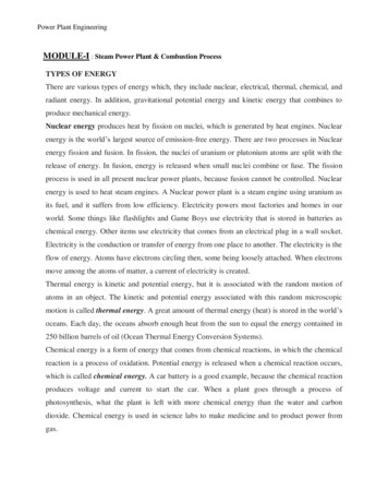
POWER PLANT ENGINEERINGCourse Code:A70353,JNTUH R-15IV B-TECH, I-SEMPrepared ByMr. G. Sarat Raju, Assistant Professor.Mrs. G. Karunya, Assistant Professor.Mechanical Engineering.INSTITUTE OF AERONAUTICAL ENGINEERING(Autonomous)Dundigal, Hyderabad - 500 043
UNIT – IINTRODUCTION TO THESOURCES OF ENERGY2
DefinitionA power station (also referred to as a generating station, powerplant, powerhouse or generating plant) is an industrial facility forthe generation of electric power.3
Types of Power Plants1.BASED ON INPUT ENERGY /FUEL(a.)COAL thermal Power Plants(b.) HYDRAULIC Power Plants(c.) NUCLEAR Power Plants(d.) GEOTHERMAL Power Plants(e.) SOLAR Power Plants(f.)WIND power plants(g.)BIOMASS power plant4
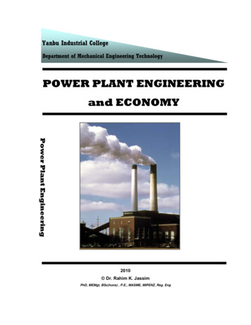
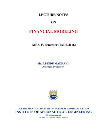
Coal Thermal Power Plant In coal thermal power plantsThe heat produce by burningfossil fuel materials boils waterand transform it into steam. The steam is then piped to aturbine. -The impulses ofturbine moves the turbine. Finally, steam is condensed andmove into the boiler to repeatthe cycle. Rotation of the turbine rotatesthe generator to produceelectricity.5
6
COMPONENTSMAIN PARTS OF THE PLANT ARE : COAL HANDLING PLANT PRE TREATMENT and DM PLANT COOLING TOWER BOILER and its Components ASH HANDLING PLANT TURBINE GENERATOR TRANSFORMERS SWITCH YARD7
CHP (Coal HandlingPlant)8
PROCESS OF CHP1.Here Subbituminous type„F‟ grade coal isused in the boiler.2. The size of thecoal is 0.6 mm.3. It is very lowquality coalwhich contain 5060% ash.9
MAIN EQUIPMENT IN CHP1.2.3.4.5.CRUSHERVIBRATING SCREENCONVEYERMAGNETIC SEPARATORVIBRO FEEDER10
IMPACT CRUSHER11
DOUBLE ROLL CRUSHER12
VIBRATING SCREEN13
MAGNETIC SEPERATOR14
VIBRO FEEDER15
PROCESS OF PRE TREATMENT PLANTRESERVOIR (Mahanadi, Kelo)STEALING CHAMBER (Cl2 dozing)PARSELL FLUME (5% Polly Aluminium Chloride dozing)INNER CELL CLEARIFIER (Removes sludges)OUTER CELL CLEARIFIERRGF (Rapid Gravity Filter)FWS (Filtered Water Storage)16
PROCESS OF DM PLANTThe main aim of DM Plant is to de-mineralised the raw water coming from a watersource by chemical dosing which may be harmful to the pipeline and boilers.ACF (Activated Carbon Filter) – contain charcoal to absorb chlorine.LBC (Layer Bed Cation) – contain resin to remove ve mineralsDEGASSER TOWER – removes CO2.WBA (Weak Base Anion) – contain resin to remove –ve minerals.SBA (Strong Base Anion) – it also contain resin to remove remaining chargedminerals.MB (Mixed Bed) - having both WBA and SBA to remove silica.17
COOLING TOWER1. The Warm Water is taken from theCondenser Tubes to the CoolingTower.2. This Breaks the water up into a VeryFine Spray Increasing the surface areaof the Water Droplets making it easierto cool.3. The cool water is collected in pond atthe bottom of the cooling tower.4. From here it pumped back tocondenser.18
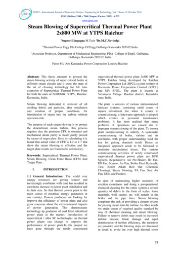
BOILER AND ITS COMPONENTS1. To produce steam boiler converts energy, in theform of coal, into steam.2. The boiler is lined with steel tubing in which purewater is turned to steam by the heat created fromthe burning of coal.3. The plant mainly of two types:I. AFBC (Air Fluidise Bed Combustion)II. WHRC ( Waste Heat Recovery Boiler)4. BOILER CAPACITY– 165 TPH (Ton Per Hour)5. STEAM PRESSURE– 90 Kg/Cm26. STEAM TEMPERATURE– 540 Oc19
layout of steam power plant20
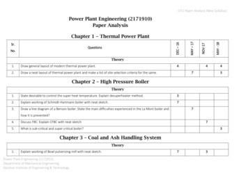
BOILER COMPONENTSForced Draft (Fd) FanThis fan forces the atmospheric air through the boiler furnace and pushes out thehot gases from the furnace through super heater, economizer, and air heater tostacks.Induced Draft (Id) Fan1. This fan is provided at the outlet of the boiler, that is just before the stack.2. This fan sucks hot gases from the furnace through the super heaters, economizerand discharges gas into the stack.Primary Air (Pa) FanThis fan are high pressure fans used to supply the air for the Transportation of coaldirectly to furnace.21
PAFANFDFANIDFAN22
ECONOMIZER1. Flue gas coming out of the boiler carries lots of heat.2. The economizer extracts a part of heat from the flue gases and uses for heatingthe feed water. thus improves the efficiency of plant.SUPERHEATER1. Super heater is used to remove moisture content from the steam.2. Super heater raises the temperature of steam above 540 oc.3. Advantages of super heater :i. increase efficiency.ii. reduces corrosion of turbine blades.AIR PREHEATER (APH)1. It is used to preheat the air before entering into furnace.2. It is a heat exchanger in which some further heat is extracted from the flue gasesand use to heat the coming air from combustion.23
24
ELECTROSTATIC PRECIPITATOR1. It is designed to trap and remove dust particles from and exhaust gas stream of anindustrial process.2. The precipitation process involves 3 main functions:i. particle chargingii. particle collectioniii. removal of particles25
DEAERATORA deaerator is a device that is widely used for the removal of oxygen and otherdissolved gases from the feed water. in particularly, dissolved oxygen in boiler feedwaters will cause serious corrosion damage in steam systems by attaching to the wallsof metal piping and other metallic equipment and forming oxides (rust).26
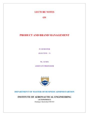
CONDENSER1. Here the steam is condensed back into water and pumped back to the boiler.2. This happens via a series of low and high pressure heaters.CONDENSATE EXTRACTION PUMPThe condensate water is drawn from the condenser by extraction pump and send itto low pressure feed heater.LOW PRESSURE FEED HEATER (LP HEATER)1. Feed water from the condensate extraction pumps pass through low pressureheater.2. Steam is used to heat the feed water.HIGH PRESSURE HEATERWith similar purpose, the high pressure feed heaters are the last stage of feed water27heating before the feed water enters the boiler system at the economizer.
CONDENSERCEPLPHP28
BOILER FEED PUMP1. The boiler feed pump pumpsthe water into the boiler, overcomingpressure of 150 kg/cm².2. The pump is driven by an electric motor.3. The pump run in 4130 rpm and the motor runs in 1490 rpm.CIRCULATING WATER PUMPSThe circulating water pumps are used to circulate the water fromcooling tower to the condenser and back again.29
COMPRESSOR HOUSE1. Themain purpose of the compressor house is to provide or supplythe high pressure air to the different components in plant.2. There are 2 types of compressed air:i.SERVICE AIR which contains moisture and is supply to ash handling plantand other services where moisture not damage any equipment.ii.INSTRUMENT AIR which contain no moisture in air and this air isused in Pneumatic valves.30
BFPCIRCULATINGPUMPCOMPRESSOR31HOUSE
ASH HANDLING PLANTAfter the coal is burn the ash of the coal remains in the esp systemso to remove that ash from the plant there is an ash handling plantjust near the boiler. the wet ash is dumped in dumping area and thedry ash is used in brick and cement making.DRY ASH SYSTEMFly ash is considered to be collected in esp. hoppers. fly ash fromesp. hoppers extracted by vacuum pumps up to intermediate surgehopper cum bag filter for further dry conveying to fly ash silo.WET ASH SYSTEMBottom ash slurry and fly ash slurry shall be pumped from thecommon ash slurry sump up to the dyke area which is located at adistance from slurry pump house.32
SILOWETDRY33
TRANSFORMER1. Transformer is the mostconvenient device for transformerof power from one voltage toanother voltage at the samefrequency.2. It works in the principle ofelectromagnetic induction.3. Transformers are of two types :i. step-up transformerii. step-down transformer34
SWITCH YARDElectrical switchyards areusually part of substationwhere electricity istransformed from onevoltage to another for thetransmission , distribution.35
UNIT-IIINTERNAL COMBUSTION ENGINEPLANT36
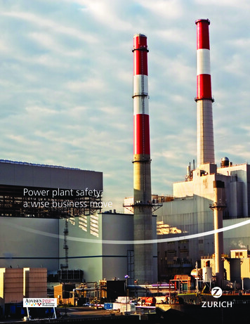
INTERNAL COMBUSTIONENGINE PLANT: DIESEL POWER PLANT The oil engines and gas engines are called InternalCombustion Engines. In IC engines fuels burn inside the engineand the products of combustion form the working fluid thatgenerates mechanical power. Whereas, in Gas Turbines thecombustion occurs in another chamber and hot working fluidcontaining thermal energy is admitted in turbine.37
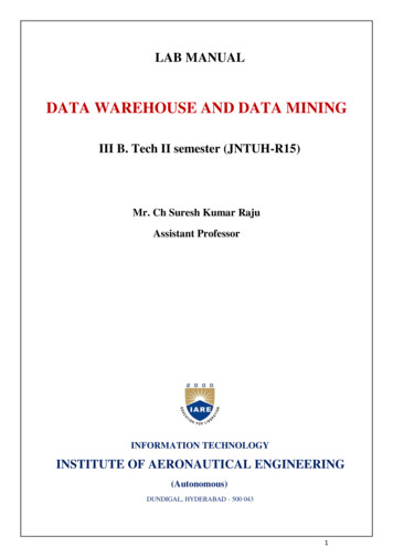
LAYOUT OF DIESEL POWER PLANTS WITH AUXILLIARIES:38
FUEL SUPPLY SYSTEM:The five essential functions of a fuel injection systemare: To deliver oil from the storage to the fuel injector. To raise the fuel pressure to the level required foratomization. To measure and control the amount of fuel admittedin each cycle. To control time of injection. To spray fuel into the cylinder in atomized form forthorough mixing and burning.39
The above functions can be achieved in avariety of ways. The following are thesystems, which are usual on power stationdiesels:– Common Rail.– Individual Pump Injection.– Distributor.40
COMMON RAIL INJECTIONIt incorporates a pump withbuilt in pressure regulation,which adjusts pumping rate tomaintain the desired injectionpressure.41
INDIVIDUAL PUMP INJECTIONIn this system, each fuel nozzle isconnected to a separate injectionpump, The pump itself does themeasuring of the fuel charge andcontrol of the injection timing. Thedelivery valve in the nozzle isactuated by fuel-oil pressure.42
DISTRIBUTOR SYSTEMIn this system, the fuel is meteredat a central point i.e., the pumpthat pressurizes, meters the fuel andtimes the injection. From here, thefuel is distributed to cylinders incorrect firingorderby camoperated poppet valves, whichopen to admit fuel to nozzles.43
LUBRICATION SYSTEMThe main function of lubricant is to, To reduce friction and wear between the parts having relativemotion by minimizing the force of friction and ensures smoothrunning of parts. To seal a space adjoining the surfaces such as piston ringsand cylinderliner. To clean the surface by carrying away the carbon and metalparticles caused by wear. To absorb shock between bearings and other parts andconsequently reduce noise.44
LUBRICATION SYSTEM45
AIR INTAKES AND ADMISSION SYSTEM46
COOLING SYSTEMNATURAL CIRCULATIONSYSTEM: The system isclosed one and designed sothat the water may circulatenaturally because of thedifference in density of waterat different temperatures.47
FORCED CIRCULATION COOLING SYSTEMThe system consists ofpump, water jacket in thecylinder, radiator, fan and athermostat.48
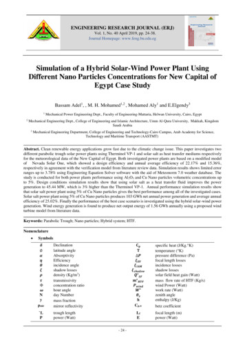
GAS TURBINE PLANT: OPEN CYCLE GAS TURBINE POWER PLANTA simple open cycle gas turbineconsists of a compressor,combustion chamber and aturbine as shown in Fig. Thecompressor takes in ambientair and raises its pressure. Heatisadded to the air incombustionchamberbyburning the fuel and raises itstemperature.49
CLOSED CYCLE GAS TURBINE POWERPLANTIn closed cycle gas turbine plant,the working fluid (air or any othersuitable gas) coming out fromcompressor is heated in a heaterby an external source at constantpressure. The high temperatureand high- pressure air coming outfrom the external heater ispassed through the gas turbine.50
DIRECT ENERGY CONVERSION FUEL CELLS:THERMO ELECTRIC SYSTEM:51
SOLAR POWER PLANT That kind of power plants createsenergy by transforming the heat andlight from the sun.There are Two types:- Solar Thermal Energy :- It stores theheat of the sun, which transformswater into steam, that moves turbineswhich are connected to a generatorthat collect energy. Photovoltaic Energy :- Is a method ofgenerating electrical power byconverting solar radiation into directcurrent electricity.52
WIND POWER PLANT Wind station are the onesthat transform wind energyinto another useful kind ofenergy A wind form consist ofalmost a hundred of windsturbines connected toelectric power transmissionnetwork53
UNIT-IIIHYDRO ELECTRIC POWERPLANT54
HYDRAULIC POWER PLANT The hydroelectric powerplants are stations whereenergy is produced bythe force of fallingwater The water moves aturbine connected to agenerator that collectthe energy that watercreates55
HYDROLOGICAL CYCLEThe generation of electric energyfrom falling water is only a smallprocess in the mighty heat powercycle known as “Hydrological cycle”or rain evaporation cycle”. It isthe process by which the moisturefrom the surface of water bodiescovering the earth‟s surface istransferred to the land and back tothe water bodies again. This cycle isshown in Fig.3.1. The input tothis cycle is the solar energy.56
HYDROGRAPH:A hydrograph indicates thevariation of discharge or flowwith time. It is plotted withflows as ordinates and timeintervals as abscissas. The flowis in m3/sec and the timemay be in hours, days, weeksor months.57
PUMPED STORAGE PLANTS: These plants supply thepeak load for the base loadpower plants and pumpall or a portion of their ownwater supply. The usualconstruction would be a tailwater pond and a head waterpond connected through apenstock.58
TYPES OF DAMS: MASANORYDAMS Solid gravity dams Buttress dams Arch dams EARTHFILL DAMS Earth fill dams Rock fill dams59
SOLID GRAVITY DAMS:A gravity dam is onewhich depends entirely onits own mass for stability.The basic gravity profileis triangular in shape, butfor practical purposes, ismodified at the top.60
TYPES OF SPILLWAYS: Overflow spillway Chute spillway Shaft spillway Siphon spillway61
Overflow spillway:Open channel spillways areDam spillways that utilize theprinciples of open-channel flowto convey impounded water inorder to prevent dam failure.They can function as principalspillways, emergency spillways,or both. They can be located onthe dam itself or on a naturalgrade in the vicinity of the dam.62
UNIT-IVNUCLEAR POWER STATION63
Nuclear Thermal Power Plant The heat is produced byfission in a nuclearreactor (a light waterreactor). Directly orindirectly, water vapour(steam) is produced. Thepressurized steam is thenusually fed to a multistage steam turbine.64
Geothermal Power Plant Geothermal electricity iselectricity generatedfrom geothermal energy.Technologies in useinclude dry steam powerpl
POWER PLANT ENGINEERING Course Code:A70353,JNTUH R-15 IV B-TECH, I-SEM Prepared By Mr. G. Sarat Raju, Assistant Professor. Mrs. G. Karunya, Assistant Professor. Mechanical Engineering. INSTITUTE OF AERONAUTICAL ENGINEERING (Autonomous) Dundigal, Hyderabad - 500 043. UNIT –I INTRODUCTION TO THE SOURCES OF ENERGY 2. Definition A power station (also referred to