Transcription
Multiprotocol Label Switching(MPLS) and ApplicationsHow Flows and a CentralizedControl Plane Augment DistributedIP Routing
Outline Review of Circuit Switching v.s. PacketSwitching Multi Protocol Label Switching (MPLS)Protocol Traffic Engineering with MPLS Path Computation Engine Architecture andProtocol
Review of CircuitSwitching v.s. PacketSwitching
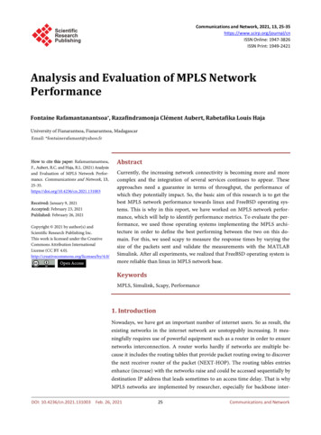
Packet switching vs. circuitswitching Packet switching Data traffic divided into packets Circuit switching Source first establishes a connection to thedestination Each router on the path may reservebandwidth Each packet contains its ownheader (with address) Packets sent separately throughthe network Router performs longest prefixmatching at each hop Destination reconstructs themessageExample: sending a letterthrough postal system Switches send data on a predetermined pathSource sends data over the connection No destination address, since routers know thepath Source tears down the connection when doneExample: voice conversation on telephonenetwork circa 1970Source:http://inst.cs.berkeley.edu/ eecsba1/sp98/reports/eecsba1a/tech packets.jpg
Advantages of circuit switching Guaranteed bandwidth Predictable communication performance Not “best-effort” delivery with no real guarantees Simple abstraction Reliable communication channel between hosts No worries about lost or out-of-order packets Simple forwarding means cheaper hardware Forwarding based on time slot or frequency No “longest prefix match” on each packet Low overhead Only data sent, control plane context kept in switches No IP, TCP, UDP headers on packets
Disadvantages of circuitswitching Wasted bandwidth Bursty traffic leads to idle connection during silentperiod Unable to achieve gains from statistical multiplexing Blocked connections Connection refused when bandwidth is not sufficient Unable to offer “okay” service to everybody Connection set-up delay No communication until the connection is set up Unable to avoid extra latency for small data transfers Network state Switches must store per-connection information Unable to avoid per-connection storage and statefailover
We could have all the advantages of circuit-switchingwithout any of the -content/uploads/what-if.jpg
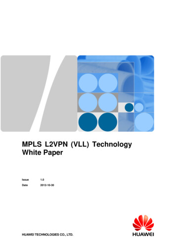
Asychronous Transfer Mode(ATM) Layer 2 standard developed inthe late 1980s and early 1990s Alternative to Ethernet Packets divided into equal sizedcellsATM: 53 bytes per cell Ethernet: packet sizes are variable Virtual circuits set up betweensender and receiver Could be long lasting Asynchronous time divisionmultiplexing used at the physicallayer Widely deployed in operatornetworks in mid to late 1990s ATM superseded by opticalswitching for transport atm forum.gif
Virtual circuits Hybrid of packet and circuit switching Logical circuit between a source anddestination Packets from different VCs multiplex on a link Virtual Circuit Identifier (VC ID)Source set-up: establish path for the VC Switch: mapping VC ID to an outgoing link Packet: fixed length label in the header 121: 72: 7link 71: 142: 8link 14link 8
Swapping the label at each hop Problem: using VC ID along the whole path Each virtual circuit consumes a unique ID Starts to use up all of the ID space in the network Label swapping Map the VC ID to a new value at each hop Table has old ID, next link, and new ID Allows reuse of the IDs at different links121: 7: 2020: 14: 78link 72: 7: 5353: 8: 42link 14link 8
Virtual Circuit Data Format Similar to IP datagrams Sender divides data into packets Packet has an addressIP address for IP VC ID for virtual circuit Store-and-forward transmission Multiple packets may arrive at once Buffer packets that can’t be immediately forwarded Multiplexing on a link No reservations: statistical multiplexing Packets are interleaved without a fixed pattern Reservations: resources for group of packets Guarantees to get a certain number of “slots”
How Virtual Dircuits Differ from IP Forwarding look-up Virtual circuits: small fixed-length connection id IP: destination IP address 4 or 16 bytes Initiating data transmission Virtual circuits: must signal along the path IP: just start sending packets Router state Virtual circuits: routers know about connections IP: no state, easier failure recovery Quality of service Virtual circuits: resources and scheduling perVC IP datagrams: difficult to provide QoS
Multi Protocol LabelSwitching (MPLS) protocol
Multiprotocol Label Switching Apply the Virtual Circuit idea from ATM to IPforwarding Why Multi Protocol? Originally designed to handle more than just IP IPX (ancient Xerox L3 protocol used by Novell Networks in the1990’s) Appletalk (still used today in some cases) Some future network protocol? Wildly successful Widely adopted by vendors (especially Cisco) Most carriers run an MPLS core Many also run MPLS access/aggregation networks Alternative for access/aggregation is carrier Ethernet(802.1aq)
IETF Standardization First MPLS Working Groupin IETF formed in 1997 First standards track RFCpublished in 2001 WG still going strongtoday140 RFCs 16 WG drafts New applications keeppopping up Most recent is f-logo.gif
Layer 2.5 Protocol Insert label between Layer 2 and Layer 3 header Fields 20 bit routing label 3 bit “Exp” field carries packet queuing priority for Class ofService 1 bit “Bottom of Stack” field 8 bit Time To Live field Labels can be stackedEthernetMPLS LabelHeaderlabel20PayloadIP headerHeaderIPExp S TTL318labelExp S TTL
Simple Data Plane Operations Pushing: add the initial “in” label (stack) Swapping: map “in” label to “out” label(stack) Popping: remove the “out” label (stack)PushingIPIPAIPBIPCR2R1IP edgePoppingSwappingR4R3MPLS coreD
Identity and Location An IP address encodes both the location of anode and the node’s identitySubnet prefix encodes location in topology Prefix plus node suffix encodes the identity of theend node Prefix alone encodes the identity of a subnet MPLS labels just encode the path to a locationIP AddressIP SubnetCalculatelocationNodePop labelstack whenarrivePush labelstack tolocationIPABCR4R3MPLS coreNodeIPR2R1IP edgeIP SubnetIPIPIdentifyend nodeand deliverD
Forwarding Equivalence Class(FEC) FEC: A rule for grouping packets according to their destination location andforwarding treatment All packets in a FEC are labelled the same way FEC is calculated at the entry point to the MPLS network Example FECs Destination prefix Rule: Longest-prefix match in forwarding table to determine route Useful for: Conventional destination-based forwarding Src/dest address, src/dest port, and protocol Rule: Five-tuple match Useful for: Quality of service treatment of the traffic Sent by a particular customer site Rule: Incoming interface Useful for: Virtual private networks A label is a locally significant identifier for a FECForwarding Equivalence Class is just anothername for an aggregated flow!
Terminology A MPLS labelled path is called a label-switchedpath (LSP)One way only For two way, add another label in opposite direction An MPLS router at the start/end of an LSP iscalled a label-edge router (LER)Start: classifies packets, inserts label (stack) beforefowarding onto LSP End: Pops label (stack), forwards according to IPlongest prefix matching An MPLS router in the middle of an LSP is called alabel-switched router (LSR) Forwards according to the top of stack label
Operation of an MPLS Router MPLS control plane sets label to forwardingtreatment mapping from outside Control plane is very complex An LSR/LER maintains a Label ForwardingInformation Base (LFIB)Like FIB, maintained in the line card Soft state, so must be refreshed periodically LFIB contains MPLS stack operation foreach label valuePush, pop, swap Outgoing interface for each label value
Operation of a Start LER FEC classifier examines IP header and determineswhich label (stack) to insert Label (stack) insertion puts label (stack) between IPand Ethernet header LFIB lookup determines what outgoing interface touse Labelled packet sent through router switch fabric tooutgoing interfaceOutgoing packeIncoming packetIPFEC (flow)ClassifierLabel(Stack)InsertionLFIBLookupIP
Operation of an LSR Look up Top of Stack label in the LFIB Does label stack need changing? If so push, pop or swap Labelled packet sent through the routerswitch fabric to outgoing interfaceOutgoing packetIncoming packetIPLFIBLookupIPLabelStackChange
Operation of an End LER Examine top of stack label Is “Bottom of Stack” bit set? Is label value “Explicit NULL Label”? 0 for IPv4 2 for IPv6 Pop label and send to appropriate IPforwarding engineIncoming packetIPToS LabelIndicatesLSP ExitPop LabelForwardusing IPLongestPrefixMatchingOutgoing packetIP
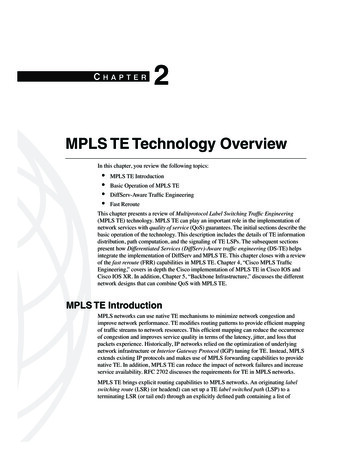
MPLS versus IP pathsR6DR4R3R5AR2 IP routing: path to destinationdetermined by destinationaddress aloneIP router
MPLS versus IP pathsR1LER1LSR1 can use different MPLS paths to Abased, e.g., on source addressDR2LSR1ALSR2 LER2IP routing: path to destinationdetermined by destinationaddress aloneMPLS routing: path todestination can be based onsource and dest. addressIP-onlyrouterMPLS andIP routerMPLS forwarding decisions can differ from IP!
Complex Control Plane MPLS Control Plane isvery complex A new control plane foreach new application E.g. TE, VPN, etc. Adapted from existingprotocolsExtensions added torouting protocols Some protocolsrepurposed for MPLSapplications MPLS DataPlaneMPLS ControlPlane E.g. RSVP MPLS specific protocols Label DistributionProtocol (LDP)Source: http://www.savvycomsoftware.com
Example 1: BGP-Free coreiBGPeBGPALSR2LER2BC 12.1.1.0/24LER1LSR1DFEC based onthe destination Routers LSR1 and LSR2prefixdon’t need to speak BGP Complexity reduction because iBGP peers need to be fully meshed Control Plane Protocol IGP (OSPF, IS-IS) extended to distribute topology and traffic information Label Distribution Protocol (LDP) used to set up LSPs
Example 2: VPNs with wo FECsLER1LSR210.1.0.0/24 Direct trafficto orangeD10.1.0.0/24 Different LSPs used for green VPN and orange VPN Control Plane depends on type of VPN L3VPN: Multiprotocol BGP L2VPN VPLS: Label Distribution Protocol (LDP) or network management system Ethernet VPN (eVPN): Multiprotocol BGP
Traffic Engineering withMPLS
What is Traffic Engineering? Traffic Engineering: Control and optimization ofrouting, to steer traffic throughthe network in the most costeffective way Costs:Cost of congestion Cost of violating customerService Level Agreements (SLAs) Transit costs Decision variables: Bandwidth Latency For voice and real time video traffic Why not just use routing? Link state IGPs only use oneequal cost path at a time May want to send some trafficover a higher cost linkSource: wikipedia.org
Traffic Engineering (TE) withConstraint-Based Routing Path calculation uses constrained shortest-path first Compute shortest path based on weights Exclude paths that do not satisfy constraints Constraint example: insufficient bandwidth Constraint information dissemination Extend OSPF/IS-IS to carry the constraint information Link-state attributes for available bandwidth LSRs calculate Traffic Engineering Database (TED) Path signaling Establish label-switched path on explicit route withRSVP-TE Forwarding MPLS labels
Traffic Engineering Database(TED) With distributed control plane, every routerin the Traffic Engineered network calculatesa TED For every link between routeri and routerj inthe TE domain:Administrative group (color) Traffic engineering metric for TE calculation Topology info Local interface IP address Remote interface IP address Bandwidth Maximum link bandwidth Maximum reservable bandwidth Available bandwidth
TED ExampleNodeID: R5.00(10.0.0.5)Type: Rtr , Age: 103 secs, LinkIn: 3, LinkOut: 3Protocol: IS-IS(2)To: R1.00(10.0.0.1), Local: 10.1.15.2, Remote: 10.1.15.1Color: 0x100 redMetric: 10Static BW: 155.52MbpsReservable BW: 155.52MbpsAvailable BW [priority] bps:[0] 155.52Mbps [1] 155.52Mbps [2] 155.52Mbps [3][4] 155.52Mbps [5] 155.52Mbps [6] 155.52Mbps [7]Interface Switching Capability Descriptor(1):Switching type: PacketEncoding type: PacketMaximum LSP BW [priority] bps:[0] 155.52Mbps [1] 155.52Mbps [2] 155.52Mbps [3][4] 155.52Mbps [5] 155.52Mbps [6] 155.52Mbps [7]To: R4.00(10.0.0.4) , Local: 10.1.45.2, Remote: 10.1.45.1Color: 0 none Metric: 10Static BW: 155.52MbpsReservable BW: 155.52MbpsAvailable BW [priority] bps:[0] 155.52Mbps [1] 155.52Mbps [2] 155.52Mbps [3][4] 155.52Mbps [5] 155.52Mbps [6] 155.52Mbps [7]Interface Switching Capability Descriptor(1):Switching type: PacketEncoding type: PacketMaximum LSP BW [priority] bps:[0] 155.52Mbps [1] 155.52Mbps [2] 155.52Mbps [3][4] 155.52Mbps [5] 155.52Mbps [6] 155.52Mbps [7][.Output truncated.]-This is Node 53 input links and 3 output linksType is router (could also be network)Softstate age is 103 secondsRouting protocol is IS-IS Level 2Link to Node 1 has local IP 10.1.15.2 andremote IP ative group is redLS-TE Metric is 10Static Bandwidth is 155.52 MbpsReservable Bandwidth is 155.52 MbpsAvailable bandwidth by Priority(3 bitToS) level
Control Plane for MPLS TE LS Routers in core floods TE information using OSPF, IS-IS link-stateprotocols Link bandwidth, amount of “reserved” link bandwidth Calculate TED Entry (head) end LER signals forward along path to request a tunnel withRSVP-TE PATH message Exit (tail) end LER signals backward along path to reserve bandwidthwith RSVP-TE RESV message Entry router knows it can use the tunnel when the RESV message arrivesTE TunnelRSVP-TE PATHRESVRSVP-TER6DLER2LSR2R5ALSR2LER1
Path Protection and FastReroute Realtime media (voice, real time video) requiresmaximum failover time 60 ms for VoIP Reserve bandwidth on an alternate route Protect a label-switched path by having a stand-by Precise control over where the traffic will go Stand-by path can be chosen to be physically disjoint Ensure fast recovery from a link failure LFIB has forwarding rule for backup path at a lower priority How upstream router detects path failure Upstream router sends heartbeat packets every 10 ms Downstream router detecting failure sends failure messageto upstream router Upstream router fails over to backup path
MPLS Fast Rerouteinoutlabel label destinterface10128outADAR6001inoutlabel label l label destinterface86Aout0AR1inoutlabel label destinterface6-Aout0
Path Computation EngineArchitecture and Protocol
Use Case #1: MPLSExtension to OpticalTransportNetworks In the mid-2000’s MPLSextended to optical transportnetworks Full circle: 1980/early 90’s: ATM late 1990’s:MPLS for routers 2000’s: MPLS for optical switches Generalized MPLS (GMPLS) Labels can be mapped to opticaltransport network constructs Circuits Wavelengths Time-slots MPLS now used for “multi-layer”networksL3 routing L2 switching L1 WDM/TDM Source: metrons.com
Use Case #2: InterAS VoIP In the mid-2000’s incumbent network operatorsstarted sending all voice traffic over IP networks“Multi-service” networks IP Multimedia Subsystem control plane Today only the last hop from the analog telephoneuses old analog technology Problems: Maintaining real time traffic classification acrosstransit domains and a peering/transit points Optimal routing between operators Optimal routing within an operator Different administrative domains (ex. wireless, WAN) Different ASes in Tier 1s (ex. NTT, NTT International)
Why a Centralized Path ComputationEngine/Element (PCE)? Multilayer networks No visibility from routers with TED when calculating paths Routers handle L3 for IP routing Optical switches handle L2/L1 for transport Constraint-based path computation in a large,multi-domain network takes too much CPU time forcontrol plane processor Optical switches might not even have computation capacity TED database may contain too much information forindividual forwarding elements to handle Some optical switches don’t have much control plane memory Establishing paths between different IGP routing areasmay be inhibited from limited visibility Operator may have particular policy rules that needenforcementSolution: Centralized Path Computation Engine
PCE Separates Concerns PCE control function Collect topology and traffic engineering information from inside aparticular administrative domain Respond to requests for LSPs through the domain Respond to transit requests Requests from PCEs external to the domain about optimal paths through theinternal domain Routing/switching control plane function Set up and maintain LSPs through L1/L2 and L3 devices within anadministrative domain Ensure that LSPs connect up with optimal transit points where trafficenters/exits Data plane function Route traffic as congestion free and fast as possible in accordancewith their traffic classificationThe PCE allows the application of appropriatecomputational power where it is needed
What the PCE is Not!The InternetSource: A. Farrell, “Path Computation Element Tutorial”, MPLS 2008
Path Computation In ExistingSystems For MPLS LERs:1. NMS sends request to the LER asking for anLSP2. LER performs a path computation3. LSP is signaled4. LSP is establishedNMS In transport networks, NMS does path1computation work4LER23PathCompSource: A. Farrell, “Path Computation Element Tutorial”, MPLS 2008
Path Computation ElementProtocol (PCEP) PCEP allows a data plane element to requesta path from the PCE Data plane element is called a Path ComputationClient (PCC) Operates over TCP Reliabile and in-order delivery Security delegated to TCP (TLS, etc.) Session-based protocolPCE and PCC open a session Negotiate parameters and learn capabilities All message exchanges within the scope of thesession
PCEP Messages Open Set up session, negotiate capabilities Keepalive Heartbeat Request Ask for a path Response Respond with a path Notify PCE notifies of various conditions, e.g. currently overloaded Error Protocol error (e.g. malformed packet) Close Close session
Request / Response Message Request message provides: Start and end points Basic constraints BandwidthLSP attributesSetup/holding prioritiesPath inclusionsMetric to optimise IGP metric TE metric Hop count Associated pathsSource: ntt-review.jp Response reportsthe computed path:Explicit route Actual path metrics Or the failure to finda path
Centralized PCE stributedControl PlaneTED synchronization(ex. OSPF, IS-IS)PathComputationPath Computation Element Protocol (PCEP)ServiceRequestHead EndNodeDistributedControl PlaneProtocolAdjacentNode
Inter-PCE CommunicationInter-PCE Request/ResponsePCEPServiceRequestHead ateNode
Integration with OperationsSupport System (OSS)ServiceRequestPCE OSSNetworkManagementSystem (NMS)PCEPServiceInstantiationHead ateNode
Summary Virtual circuit has many attractions for transport networks Development of MPLS made virtual circuits available to IP networks MPLS labels packets with a 32 bit label in a label stackSimple data plane: push, pop, swap 20 bit routing label, 3 ToS bits for quality of service Packet flows are labelled according to their forwardingequivalence class A FEC is just an aggregated flow MPLS control plane differs depending on applications Traffic engineering is a major use of MPLS Operator sets up label switched paths across their network tospread load Application of MPLS to optical transport networks and otheruse cases required centralized path computation Path Computation Engine provides server-computed pathinformation to routers and optical switches
Acknowledgements Adrian Farrell, Old Dog Consulting
Extra Slides
Multiple PCERequest/ResponseServiceRequestHead gnalingIntermediateNode
MPLS versus IP paths IP-only router IP routing: path to destination determined by destination address alone MPLS and IP router MPLS routing: path to destination can be based on source and dest. address LSR1 can use different MPLS paths to A LER1 based, e.g., on source address LER2 MPLS forwarding decisions can differ from IP!