Transcription
CHAPTER33Configuring MPLS LSP Multipath Tree TraceThis chapter describes how to configure Multiprotocol Label Switching (MPLS) connectivity with theMPLS LSP Multipath Tree Trace feature.This chapter includes the following sections: Finding Feature Information, page 33-33 Information About MPLS LSP Multipath Tree Trace, page 33-33 Licensing Requirements for MPLS LSP Multipath Tree Trace, page 33-35 Prerequisites for MPLS LSP Multipath Tree Trace, page 33-35 Guidelines and Limitations for MPLS LSP Multipath Tree Trace, page 33-36 Configuring MPLS LSP Multipath Tree Trace, page 33-36 Configuration Examples for MPLS LSP Multipath Tree Trace, page 33-51 Additional References for MPLS LSP Multipath Tree Trace, page 33-60 Feature History for MPLS LSP Multipath Tree Trace, page 33-60Finding Feature InformationYour software release might not support all the features documented in this module. For the latest caveatsand feature information, see the Bug Search Tool at https://tools.cisco.com/bugsearch/ and the releasenotes for your software release. To find information about the features documented in this module, andto see a list of the releases in which each feature is supported, see the “New and Changed Information”chapter or the Feature History table below.Information About MPLS LSP Multipath Tree Trace.i.MPLS:tree trace;The MPLS LSP Multipath Tree Trace feature provides the means to discover all possible equal-costmultipath (ECMP) routing paths of a label switched path (LSP) between an egress and ingress router.Once discovered, these paths can be retested on a periodic basis using MPLS LSP ping or traceroute.This feature is an extension to the MPLS LSP traceroute functionality for the tracing of IPv4 LSPs.You can use the MPLS LSP Multipath Tree Trace feature to discover all paths for an IPv4 LSP.This implementation of the MPLS LSP Multipath Tree Trace feature is based on the IETF RFC 4379Detecting Multi-Protocol Label Switched (MPLS) Data Plane Failures.Cisco Nexus 7000 Series NX-OS MPLS Configuration GuideOL-23587-0133-33
Chapter 33Configuring MPLS LSP Multipath Tree TraceInformation About MPLS LSP Multipath Tree TraceThis section includes the following topics: Overview of MPLS LSP Multipath Tree Trace, page 33-34 Discovery of IPv4 Load Balancing Paths by MPLS LSP Multipath Tree Trace, page 33-34 Echo Reply Return Codes Sent by the Router Processing Multipath LSP Tree Trace, page 33-35Overview of MPLS LSP Multipath Tree TraceAs the number of MPLS deployments increases, the number of traffic types that the MPLS networkscarry could increase. In addition, load balancing on label switch routers (LSRs) in the MPLS networkprovides alternate paths for carrying MPLS traffic to a target router. The ability of service providers tomonitor LSPs and quickly isolate MPLS forwarding problems is critical to their ability to offer services.Before the release of the MPLS LSP Multipath Tree Trace feature, no automated way existed to discoverall paths between provider edge (PE) routers, and troubleshooting forwarding problems between PEswas difficult.The MPLS LSP Multipath Tree Trace feature provides an automated way to discover all paths from theingress PE router to the egress PE router in multivendor networks that use IPv4 load balancing at thetransit routers. Once the PE-to-PE paths are discovered, use MPLS LSP ping and MPLS LSP tracerouteto periodically test them.Discovery of IPv4 Load Balancing Paths by MPLS LSP Multipath Tree Trace.i.load balancing;IPv4 load balancing at a transit router is based on the incoming label stack and the source and destinationaddresses in the IP header. The outgoing label stack and IP header source address remain constant foreach branch being traced.When you execute MPLS LSP multipath tree trace on the source LSR, the router needs to find the set ofIP header destination addresses to use all possible output paths. The source LSR starts path discovery bysending a transit router a bitmap in an MPLS echo request. The transit router returns information in anMPLS echo request that contains subsets of the bitmap in a downstream map (DS Map) in an echo reply.The source router can then use the information in the echo reply to interrogate the next router. The sourcerouter interrogates each successive router until it finds one bitmap setting that is common to all routersalong the path. The router uses TTL expiry to interrogate the routers to find the common bits.For example, you could start path discovery by entering the following command at the source router:switch# traceroute mpls multipath ipv4 10.131.101.129/32 hashkey ipv4 bitmap 16This command sets the IP address of the target router as 10.131.101.192 255.255.255.255 andconfigures: The default hash key type to 8, which requests that an IPv4 address prefix and bit mask address setbe returned in the DS Map in the echo reply. The bitmap size to 16. This means that MPLS LSP multipath tree trace uses 16 addresses (startingwith 127.0.0.1) in the discovery of all paths of an LSP between the source router and the targetrouter.If you enter the traceroute mpls multipath ipv4 10.131.101.129/32 command, MPLS LSP multipathtree trace uses the default hash type of 8 or IPv4 and a default bitmap size of 32. Your choice of a bitmapsize depends on the number of routes in your network. If you have many routes, you might need to usea larger bitmap size.Cisco Nexus 7000 Series NX-OS MPLS Configuration Guide33-34OL-23587-01
Chapter 33Configuring MPLS LSP Multipath Tree TraceLicensing Requirements for MPLS LSP Multipath Tree TraceEcho Reply Return Codes Sent by the Router Processing Multipath LSP TreeTraceTable 33-1 describes the codes that the router processing a multipath LSP tree trace packet returns to thesender about the failure or success of the request.Table 33-1Echo Reply Return CodesOutput CodeEcho ReturnCodeMeaningPeriod “.”—A timeout occurred before the target router could reply.x0No return code.M1Malformed request.m2Unsupported type, length, values (TLVs).!3Success.F4No Forwarding Equivalence Class (FEC) mapping.D5DS Map mismatch.R6Downstream router but not target.U7Reserved.L8Labeled output interface.B9Unlabeled output interface.f10FEC mismatch.N11No label entry.P12No receive interface label protocol.p13Premature termination of the LSP.XunknownUndefined return code.Licensing Requirements for MPLS LSP Multipath Tree TraceProductLicense RequirementCisco NX-OSThe MPLS LSP Multipath Tree Trace feature requires an MPLS license. For a complete explanation of theCisco NX-OS licensing scheme and how to obtain and apply licenses, see the Cisco NX-OS Licensing Guide.Prerequisites for MPLS LSP Multipath Tree TraceThe MPLS LSP Multipath Tree Trace feature has the following prerequisites: Before you can run MPLS ping and traceroute, ensure that the Intrusion Detection System (IDS) isdisabled (specifically the option that drops packets if the IP address is in the reserved 127.x.x.xrange). You must enable the MPLS LDP feature.Cisco Nexus 7000 Series NX-OS MPLS Configuration GuideOL-23587-0133-35
Chapter 33Configuring MPLS LSP Multipath Tree TraceGuidelines and Limitations for MPLS LSP Multipath Tree Trace You must understand the concepts and know how to use MPLS LSP ping or traceroute as describedin the MPLS LSP Ping/Traceroute for LDP/TE, and LSP Ping for VCCV document. The routers in your network must use an implementation based on IETF RFC 4379 DetectingMulti-Protocol Label Switched (MPLS) Data Plane Failures. You should know the following about your MPLS network:– The topology– The number of links in your network– The expected number of LSPs, and how many LSPs Understand label switching, forwarding, and load balancing.Guidelines and Limitations for MPLS LSP Multipath Tree TraceThe MPLS LSP Multipath Tree Trace feature has the following configuration guidelines and limitations: All restrictions that apply to the MPLS LSP ping and LSP traceroute features also apply to the MPLSLSP Multipath Tree Trace feature as follows:– You cannot use the MPLS LSP Multipath Tree Trace feature to trace the path taken by AToMpackets. The MPLS LSP Multipath Tree Trace feature is not supported for AToM. (MPLS LSPping is supported for AToM.) However, you can use the MPLS LSP Multipath Tree Trace featureto troubleshoot the Interior Gateway Protocol (IGP) LSP that is used by AToM.– You cannot use the MPLS LSP Multipath Tree Trace feature to validate or trace MPLS virtualprivate networks (VPNs). Multiple LSP paths are not discovered unless all routers in the MPLScore support an RFC 4379 implementation of Detecting Multi-Protocol Label Switched (MPLS)Data Plane Failures. MPLS LSP multipath tree trace is not expected to operate in networks that support time-to-live(TTL) hiding.Configuring MPLS LSP Multipath Tree TraceThis section includes the following topics: Customizing the Default Behavior of MPLS Echo Packets, page 33-37 Configuring MPLS LSP Multipath Tree Trace, page 33-38 Discovering IPv4 Load Balancing Paths Using MPLS LSP Multipath Tree Trace, page 33-40 Monitoring LSP Paths Discovered by MPLS LSP Multipath Tree Trace Using MPLS LSPTraceroute, page 33-41 Using DSCP to Request a Specific Class of Service in an Echo Reply, page 33-43 Controlling How a Responding Router Replies to an MPLS Echo Request, page 33-44 Specifying the Output Interface for Echo Packets Leaving a Router for MPLS LSP Multipath TreeTrace, page 33-46 Setting the Pace of MPLS Echo Request Packet Transmission for MPLS LSP Multipath Tree Trace,page 33-47 Enabling MPLS LSP Multipath Tree Trace to Detect LSP Breakages Caused by an Interface ThatLacks an MPLS Configuration, page 33-48Cisco Nexus 7000 Series NX-OS MPLS Configuration Guide33-36OL-23587-01
Chapter 33Configuring MPLS LSP Multipath Tree TraceConfiguring MPLS LSP Multipath Tree Trace Requesting That a Transit Router Validate the Target FEC Stack for MPLS LSP Multipath TreeTrace, page 33-49 Setting the Number of Timeout Attempts for MPLS LSP Multipath Tree Trace, page 33-50Customizing the Default Behavior of MPLS Echo Packets.i.customized echo packets;You can customize the default behavior of MPLS echo packets. You might need to customize the defaultecho packet encoding and decoding behavior to allow later implementations of the Detecting MPLS DataPlane Failures (RFC 4379) to be deployed in networks running earlier versions of the draft.MPLS Embedded Management ConfigurationBefore using the ping mpls, traceroute mpls, or traceroute mpls multipath command, you shouldensure that the router is configured to encode and decode MPLS echo packets in a format that allreceiving routers in the network can understand.LSP ping drafts after Version 3 (draft-ietf-mpls-ping-03) have undergone numerous TLV formatchanges, but the implementations based on different drafts might not interoperate properly.To allow later Cisco implementations to interoperate with draft Version 3 Cisco and non-Ciscoimplementations, a global configuration mode (MPLS OAM configuration) allows you to encode anddecode echo packets in formats specified by draft Version 3 implementations.Unless configured otherwise, a Cisco implementation encodes and decodes echo requests assuming theversion on which the Internet Engineering Task Force (IETF) implementation is based.To allow for seamless interoperability with earlier Revision 1 and 3 images, you can use MPLSOperation, Administration, and Maintenance (OAM) configuration mode parameters to force the defaultbehavior of the Revision 4 images to be compliant or compatible in networks with Revision 1 or Revision3 images.To prevent failures reported by the replying router due to TLV version issues, you should configure allrouters in the core. Encode and decode MPLS echo packets in the same draft version. For example, ifthe network is running RFC 4379 (Cisco Revision 4) implementations but one router can run onlyVersion 3 (Cisco Revision 3), configure all routers in the network to operate in Revision 3 mode.Cisco Revision 4 is the default version. The default version is the latest LSP ping version supported bythe image on the router.PrerequisitesThe MPLS LSP Multipath Tree Trace feature requires RFC 4379 (Revision 4).SUMMARY STEPS1.configure terminal2.mpls oam3.echo revision {3 4}4.[no] echo vendor-extensionCisco Nexus 7000 Series NX-OS MPLS Configuration GuideOL-23587-0133-37
Chapter 33Configuring MPLS LSP Multipath Tree TraceConfiguring MPLS LSP Multipath Tree TraceDETAILED STEPSStep 1CommandPurposeconfigure terminalEnters global configuration mode.Example:switch# configure terminalStep 2mpls oamExample:switch(config)# mpls oamStep 3echo revision {3 4}Example:switch(config-mpls)# echo revision 4Enters MPLS OAM configuration mode andcustomizes the default behavior of echo packets.Customizes the default behavior of echo packets. The revision keyword sets echo packetattributes to one of the following:– 3 draft-ietf-mpls-ping-03 (Revision 2)– 4 RFC 4379 compliant (default)NoteStep 4[no] echo vendor-extensionExample:switch(config-mpls)# echo vendor-extensionThe MPLS LSP Multipath Tree Tracefeature requires Revision 4.Customizes the default behavior of echo packets. The vendor-extension keyword sends theCisco-specific extension of TLVs with theecho packets. The no form of the command allows you todisable a Cisco vendor’s extension TLVs thatanother vendor’s noncompliantimplementations may not support.The router default is echo vendor-extension.Configuring MPLS LSP Multipath Tree TraceYou can configure the MPLS multipath LSP tree trace traceroute. This task helps you to discover allLSPs from an egress router to an ingress router.PrerequisitesCisco LSP ping or traceroute implementations based on draft-ietf-mpls-lsp-ping-11 can in some casesdetect the formatting of the sender of an MPLS echo request. However, in certain cases an echo requestor echo reply might not contain the Cisco extension TLV. To avoid complications in which the echopackets are decoded assuming the wrong TLV formats, configure all routers in the network to operate inthe same mode.For an MPLS LSP multipath tree trace to be successful, the implementation in your routers must supportRFC 4379 on all core routers.If all routers in the network support FRC-4379 and another vendor’s implementation exists that is notcapable of properly handling Cisco’s vendor TLV, the routers supporting the RFC-compliant or laterconfiguration must include commands to disable the Cisco vendor TLV extensions.Cisco Nexus 7000 Series NX-OS MPLS Configuration Guide33-38OL-23587-01
Chapter 33Configuring MPLS LSP Multipath Tree TraceConfiguring MPLS LSP Multipath Tree TraceSUMMARY STEPS1.configure terminal2.mpls oam3.echo revision 44.(Optional) [no] echo vendor-extension5.traceroute mpls multipath ipv4 ILED STEPSStep 1CommandPurposeconfigure terminalEnters global configuration mode.Example:switch# configure terminalStep 2Enters MPLS OAM configuration mode.mpls oamExample:switch(config)# mpls oamStep 3Customizes the default behavior of echo packets.echo revision 4Example:switch(config-mpls)# echo revision 4Step 4[no] echo vendor-extensionExample:switch(config-mpls) echo vendor-extension The revision 4 keywords set echo packetattributes to the default Revision 4 (RFC 4379compliant).NoteThe MPLS LSP Multipath Tree Tracefeature requires Revision 4.(Optional) Customizes the default behavior ofecho packets. The vendor-extension keyword sends theCisco-specific extension of TLVs with theecho packets. The no form of the command allows you todisable a Cisco vendor’s extension TLVs thatanother vendor’s noncompliantimplementations may not support.The router default is echo vendor-extension.Step 5traceroute mpls multipath Example:switch# traceroute mpls multipath ipv410.131.161.251/32Discovers all LSPs from an egress router to aningress router. The ipv4 keyword specifies the destinationtype as an LDP IPv4 address. The destination-ip-address argument is theaddress prefix of the target to be tested. The destination-mask-length argument is thenumber of bits in the network mask of thetarget address. The / keyword before thisargument is required.Cisco Nexus 7000 Series NX-OS MPLS Configuration GuideOL-23587-0133-39
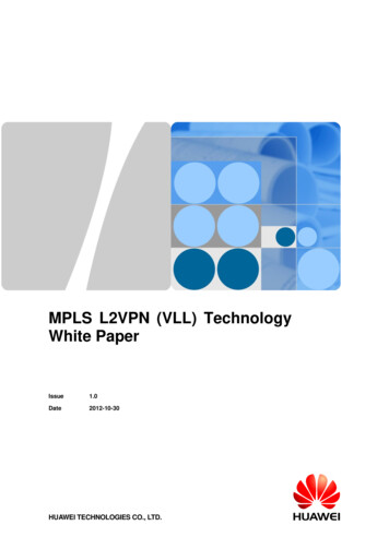
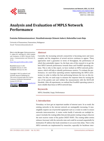
Chapter 33Configuring MPLS LSP Multipath Tree TraceConfiguring MPLS LSP Multipath Tree TraceDiscovering IPv4 Load Balancing Paths Using MPLS LSP Multipath Tree TraceYou can discover IPv4 load balancing paths using the MPLS LSP Multipath Tree Trace feature.MPLS Multipath LSP Traceroute Path DiscoveryA Cisco router load balances MPLS packets based on the incoming label stack and the source anddestination addresses in the IP header. The outgoing label stack and IP header source address remainconstant for each path being traced. The router needs to find the set of IP header destination addressesto use all possible output paths. This might require exhaustive searching of the 127.x.y.z/8 address space.Once you discover all paths from the source LSR to the target or destination LSR with the MPLS LSPMultipath Tree Trace feature, you can use MPLS LSP traceroute to monitor these paths.Figure 33-1 shows how the MPLS LSP Multipath Tree Trace feature discovers LSP paths in a samplenetwork. In Figure 33-1, the bitmap size is 16 and the numbers 0 to 15 represent the bitmapped addressesthat the MPLS LSP Multipath Tree Trace feature uses to discover all the paths from the source LSRR-101 to the target LSR R-150. Figure 33-1 illustrates how the traceroute mpls multipath commanddiscovers all LSP paths in the sample network.Figure 33-1MPLS LSP Multipath Tree Trace Path Discovery in a Sample NetworkR-120Address: 1, 2,4, 15R-131 Address: 1, 4Address: 1, 2, 3, 4,5, 7, 13, 15R-141Address: 4Address: 2, 15Address: 3, 5, 7, 13R-130Target R-150R-140Address: 15R-111Address 7, 13SourceSource R-101R-101Address 7Address: 14Address: 0, 6, 8, 9,10, 11, 12, 14R-121 Address: 6, 9,12, 14R-132170601Address: 6, 9, 14SUMMARY STEPS1.configure terminal2.mpls oam3.echo revision 44.traceroute mpls multipath ipv4 destination-ip-address/destination-mask-length hashkey ipv4bitmap bitmap-sizeCisco Nexus 7000 Series NX-OS MPLS Configuration Guide33-40OL-23587-01
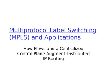
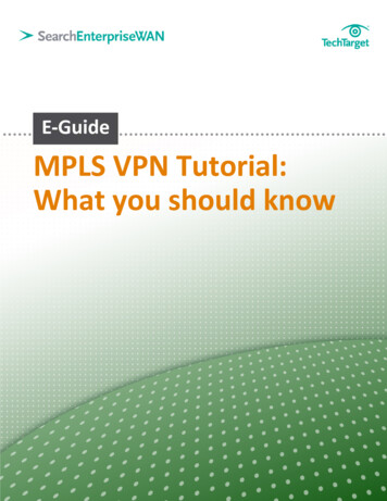
Chapter 33Configuring MPLS LSP Multipath Tree TraceConfiguring MPLS LSP Multipath Tree TraceDETAILED STEPSStep 1CommandPurposeconfigure terminalEnters global configuration mode.Example:switch# configure terminalStep 2Step 3Example:switch(config)# mpls oamEnters MPLS OAM configuration mode and setsthe echo packet attribute to Revision 4 (RFC 4379compliant).echo revision 4Customizes the default behavior of echo packets.mpls oamExample:switch(config-mpls)# echo revision 4Step 4traceroute mpls multipath hkey ipv4 bitmap bitmap-sizeExample:switch# traceroute mpls multipath ipv410.131.161.251/32 hashkey ipv4 bitmap 16 The revision 4 keywords set echo packetattributes to the default Revision 4 (RFC 4379compliant).NoteThe MPLS LSP Multipath Tree Tracefeature requires Revision 4.Discovers all MPLS LSPs from an egress router toan ingress router. The ipv4 keyword specifies the destinationtype as an LDP IPv4 address. The destination-address argument is theaddress prefix of the target to be tested. The destination-mask-length argument is thenumber of bits in the network mask of thetarget address. The / keyword before thisargument is required. The hashkey ipv4 keywords set the hashkeytype to IPv4 addresses. The bitmap bitmap-size keyword andarguments set the bitmap size for multipathdiscovery.Monitoring LSP Paths Discovered by MPLS LSP Multipath Tree Trace UsingMPLS LSP TracerouteYou can monitor LSP paths that are discovered by the MPLS LSP Multipath Tree Trace feature using theMPLS LSP traceroute. You can take output directly from the traceroute mpls multipath command andadd it to a traceroute mpls command periodically to verify that the path is still operating.Figure 33-2 shows the mapping of the output of a traceroute mpls multipath command to a traceroutempls command.Cisco Nexus 7000 Series NX-OS MPLS Configuration GuideOL-23587-0133-41
Chapter 33Configuring MPLS LSP Multipath Tree TraceConfiguring MPLS LSP Multipath Tree TraceFigure 33-2Mapping of traceroute mpls multipath Command Output to a traceroute mplsCommandswitch# traceroute mpls multipath ipv4 10.1.1.150/32 hashkey ipv4 bitmap 16source 10.1.111.101destination 127.0.0.7switch# traceroute mpls ipv4 10.1.1.1.150/32 output interface Et0/0 source 10.1.111.101destination 127.0.0.7traceroute mpls {ipv4 destination -add res s/destina tion-mask [destinatio n ad dres s-start [ad dres s-end][address-incremen t]] traffic-eng tu nnel-interface tu nnel-number} [revis ion {1 2 3 4}][so urce source-ad dress] [timeout seconds] [reply dscp dscp-va lu e] [reply pad-tlv][reply mode reply-mo de] [ttl ma ximum-time-to-live] [exp exp-bits] [revisiontlv-revision -nu mber] [force-ex plicit-null] [output interface tx-interface] [fla gs fec]239757output interface Et0/0Each path that you discover with the MPLS LSP Multipath Tree Trace feature can be tested in thismanner periodically to monitor the LSP paths in your network.SUMMARY STEPS1.traceroute mpls multipath ipv4 destination-address/destination-mask-length hashkey ipv4bitmap bitmap-size2.traceroute mpls ipv4 destination-address/destination-mask-length [output interface tx-interface][source source-address] [destination address-start]DETAILED STEPSStep 1Discover all MPLS LSPs from an egress router to an ingress router by entering the traceroute mplsmultipath ipv4 destination-address/destination-mask-length hashkey ipv4 bitmap bitmap-sizecommand.This example shows how to discover all MPLS LSPs from an egress router to an ingress router:switch# traceroute mpls multipath ipv4 10.1.1.150/32 hashkey ipv4 bitmap 16Starting LSP Multipath Traceroute for 10.1.1.150/32Codes: '!' - success, 'Q' - request not sent, '.' - timeout,'L' - labeled output interface, 'B' - unlabeled output interface,'D' - DS Map mismatch, 'F' - no FEC mapping, 'f' - FEC mismatch,'M' - malformed request, 'm' - unsupported tlvs, 'N' - no label entry,'P' - no rx intf label prot, 'p' - premature termination of LSP,'R' - transit router, 'I' - unknown upstream index,'X' - unknown return code, 'x' - return code 0Type escape sequence toLLLL!Path 0 found,output interface Et0/0LLL!Path 1 found,output interface Et0/0L!Path 2 found,output interface Et0/0abort.source 10.1.111.101 destination 127.0.0.0source 10.1.111.101 destination 127.0.0.1source 10.1.111.101 destination 127.0.0.5Cisco Nexus 7000 Series NX-OS MPLS Configuration Guide33-42OL-23587-01
Chapter 33Configuring MPLS LSP Multipath Tree TraceConfiguring MPLS LSP Multipath Tree TraceLL!Path 3 found,output interface Et0/0 source 10.1.111.101 destination 127.0.0.7Paths (found/broken/unexplored) (4/0/0)Echo Request (sent/fail) (14/0)Echo Reply (received/timeout) (14/0)Total Time Elapsed 468 msThe output of the traceroute mpls multipath command in the example shows the result of pathdiscovery with the MPLS LSP Multipath Tree Trace feature. In this example, the command sets thebitmap size to 16. Path discovery starts by the MPLS LSP Multipath Tree Trace feature using 16bitmapped addresses as it locates LSP paths from the source router to the target router with prefix andmask 10.1.1.150/32. MPLS LSP multipath tree trace starts using the 127.x.y.z/8 address space with127.0.0.1.Step 2Verify that the paths discovered when you entered a traceroute mpls multipath command are stilloperating by entering the traceroute mpls ipv4 destination-address/destination-mask-length [outputinterface tx-interface] [source source-address] [destination address-start] command.For example, the output for Path 0 in the previous traceroute mpls multipath command in Step 1 is asfollows:output interface Et0/0 source 10.1.111.101 destination 127.0.0.0If you put the output for path 0 in the traceroute mpls command, you see the following results:switch# traceroute mpls ipv4 10.1.1.150/32 output interface Et0/0 source 10.1.111.101destination 127.0.0.0Tracing MPLS Label Switched Path to 10.1.1.150/32, timeout is 2 secondsCodes: '!' - success, 'Q' - request not sent, '.' - timeout,'L' - labeled output interface, 'B' - unlabeled output interface,'D' - DS Map mismatch, 'F' - no FEC mapping, 'f' - FEC mismatch,'M' - malformed request, 'm' - unsupported tlvs, 'N' - no label entry,'P' - no rx intf label prot, 'p' - premature termination of LSP,'R' - transit router, 'I' - unknown upstream index,'X' - unknown return code, 'x' - return code 0Type escape sequence to abort.0 10.1.111.101 MRU 1500 [Labels:L 1 10.1.111.111 MRU 1500 [Labels:L 2 10.2.121.121 MRU 1500 [Labels:L 3 10.3.132.132 MRU 1500 [Labels:L 4 10.4.140.240 MRU 1504 [Labels:! 5 10.5.150.50 20 ms33 Exp: 0]34 Exp: 0] 4034 Exp: 0] 3232 Exp: 0] 16implicit-nullmsmsmsExp: 0] 20 msYou can take output directly from the traceroute mpls multipath command and add it to a traceroutempls command periodically to verify that the path is still operating (see Figure 33-2).Using DSCP to Request a Specific Class of Service in an Echo ReplyUse the reply differentiated services code point (DSCP) option to request a specific class of service(CoS) in an echo reply.Cisco Nexus 7000 Series NX-OS MPLS Configuration GuideOL-23587-0133-43
Chapter 33Configuring MPLS LSP Multipath Tree TraceConfiguring MPLS LSP Multipath Tree TraceThe reply DSCP option is supported in the experimental mode for IETF draft-ietf-mpls-lsp-ping-03.txt.Cisco implemented a vendor-specific extension for the reply DSCP option rather than using a Reply TOSTLV. A Reply TOS TLV serves the same purpose as the reply dscp command in IETFdraft-ietf-mpls-lsp-ping-11.txt. This draft provides a standardized method of controlling the reply DSCP.SUMMARY STEPS1.traceroute mpls multipath ipv4 destination-address/destination-mask-length [reply dscpdscp-value]DETAILED STEPSStep 1CommandPurposetraceroute mpls multipath ply dscp dscp-value]Discovers all MPLS LSPs from an ingress routerto an egress router and controls the DSCP value ofan echo reply.Example:switch# traceroute mpls multipath ipv410.131.191.252/32 reply dscp 50 The ipv4 keyword specifies the destinationtype as an LDP IPv4 address. The destination-address argument is theaddress prefix of the target to be tested. The destination-mask-length argument is thenumber of bits in the network mask of thetarget address. The / keyword before thisargument is required. The reply dscp dscp-value keywords andargument are the DSCP value of an echo reply.A Reply TOS TLV serves the same purpose asthe reply dscp command in IETFdraft-ietf-mpls-lsp-ping-11.txt.NoteTo specify a DSCP value, you must enterthe reply dscp dscp-value keywords andargument.Controlling How a Responding Router Replies to an MPLS Echo RequestThis section describes how to control how a responding router replies to an MPLS echo request.This section includes the following topic: Reply Modes for an MPLS LSP Multipath Tree Trace Echo Request Response, page 33-44Reply Modes for an MPLS LSP Multipath Tree Trace Echo Request ResponseThe reply mode controls how a responding router replies to an MPLS echo request sent by a traceroutempls multipath command. There are two reply modes for an echo request packet: ipv4—Reply with an IPv4 User Datagram Protocol (UDP) packet (default) router-alert—Reply with an IPv4 UDP packet with router alertCisco Nexus 7000 Series NX-OS MPLS Configuration Guide33-44OL-23587-01
Chapter 33Configuring MPLS LSP Multipath Tree TraceConfiguring MPLS LSP Multipath Tree TraceNoteUse the ipv4 and router-alert reply modes with each other to prevent false negatives. If you do not receivea reply via the ipv4 mode, send a test with the router-alert reply mode. If both fail, something is wrongin the return path. The problem might be due to an incorrect ToS setting.IPv4 UDP Reply ModeThe IPv4 UDP reply mode is the most common reply mode used with a traceroute mpls multipathcommand when you want to periodically poll the integrity of an LSP. With this option, you do not haveexplicit control over whether the packet traverses IP or MPLS hops to reach the originator of the MPLSecho request. If the originating (headend) router fails to receive a reply to an MPLS echo request whenyou use the reply mode ipv4 keywords, use the reply mode router-alert keywords.Router-Alert Reply ModeThe router-alert reply mode adds the router alert option to the IP header. When an IP packet that containsan IP router alert option in its IP header or an MPLS packet with a router alert label as its outermost labelarrives at a router, the router punts (redirects) the packet to the supervisor process level for handling,which forces the supervisor of each intermediate router to handle the packet at each intermediate hop asit moves back to the destination. Hardware and line card forwarding inconsistencies are thus bypassed.Router-alert reply mode is slower than IPv4 mode because the reply requires process-level supervisorhandling at each hop.Table 33-2 describes how an incoming IP packet with an IP router alert is handled by the router switchingpath processes when the outgoing packet is an IP packet or an MPLS packet. It also describes how anMPLS packet with a router alert option is handled by the router switching path processes when theoutgoing packet is an IP packet or an MPLS packet.Table 33-2Path Process Handling of IP and MPLS Router Alert PacketsIncoming PacketOutgoing PacketSoftware Switching ActionIP packet—Router alertoption in IP headerIP packet—Router alertoption in IP headerForwards the packet as is.MPLS packetForwards the packet as is.IP packet—Router alertoption in IP headerRemoves the outermost routeralert label and forwards thepacket as an IP packet.MPLS packet—Outermost label containsa router alertSUMMARY STEPS1.traceroute mpls multipath ipv4 destinati
The MPLS LSP Multipath Tree Trace feature has the following configuration guidelines and limitations: † All restrictions that apply to the MPLS LSP ping and LSP traceroute features also apply to the MPLS LSP Multipath Tree Trace feature as follows: - You cannot use the MPLS LSP Multipath Tree Trace feature to trace the path taken by AToM .