Transcription
Journal of Minerals & Materials Characterization & Engineering, Vol. 10, No.9, pp.777-803, 2011jmmce.org Printed in the USA. All rights reservedStudies on Cold Workability Limits of Brass Using Machine Vision Systemand its Finite Element AnalysisJ. Appa Rao1, J. Babu Rao1*, Syed Kamaluddin2 and NRMR Bhargava112Dept of Metallurgical Engineering, Andhra University, Visakhapatnam – 530 003, IndiaDept of Mechanical Engineering, GITAM University, Visakhapatnam – 530 045, India*Corresponding Author: baburaojinugu@yahoo.comABSTRACTCold Workability limits of Brass were studied as a function of friction, aspect ratio andspecimen geometry. Five standard shapes of the axis symmetric specimens of cylindricalwith aspect ratios 1.0 and 1.5, ring, tapered and flanged were selected for the presentinvestigation. Specimens were deformed in compression between two flat platens to predictthe metal flow at room temperature. The longitudinal and oblique cracks were obtained asthe two major modes of surface fractures. Cylindrical and ring specimen shows the obliquesurface crack while the tapered and flanged shows the longitudinal crack. Machine Visionsystem using PC based video recording with a CCD camera was used to analyze thedeformation of 4 X 4 mm square grid marked at mid plane of the specimen. The strain pathsobtained from different specimens exhibited nonlinearity from the beginning to the end of thestrain path. The circumferential stress component σ θ increasingly becomes tensile withcontinued deformation. On the other hand the axial stress σ z , increased in the very initialstages of deformation but started becoming less compressive immediately as barrelingdevelops. The nature of hydrostatic stress on the rim of the flanged specimen was found to betensile. Finite element software ANSYS has been applied for the analysis of the upset formingprocess. When the stress values obtained from finite element analysis were compared to themeasurements of grids using Machine Vision system it was found that they were in closeproximity.KEY WORDS: Friction, Upsetting, Vision System, Finite Element AnalysisNOMENCLATUREDbDe Bulge diameter End diameter777
778J Appa Rao, J Babu Rao, Syed Kamaluddin and NRMR BhargavaD0H0H0 / D0Knw0wiαεzεθεσσHσrσzσθ Vol.10, No.9Initial diameter of the cylindrical sampleInitial height of the cylindrical sampleAspect ratioStrength coefficientStrain- hardening exponentOriginal width of the square gridCurrent width of the square gridStrain ratio (slope of the strain path)Axial strainCircumferential strainEffective strainEffective stressHydrostatic stress [(σr σθ σz)/3]Radial stress componentAxial stress componentCircumferential stress component1. INTRODUCTIONMetal forming refers to a group of manufacturing methods by which the given shape of awork piece is converted to another shape without change in the mass or composition of thematerial. Forming process has become increasingly important in almost all manufacturingindustries such as aerospace, steel plants and automobiles applications. The upsetting ofsolid cylinders is an important metal forming process and an important stage in the forgingsequence of many products. Cold forming process minimizes material wastage, improvesmechanical properties such as yield strength and hardness and provides very good surfacefinish. The tools used are also subjected less thermal fatigue [1-4]. Metal flow is influencedmainly by various parameters like specimen geometry, friction conditions, characteristics ofthe stock material, thermal conditions existing in the deformation zone, and strain rate. Metalflow influence the quality and the properties of the formed product; the force and energyrequirements of the process. A large segment of industry depends primarily on thepredominant applications of this process which includes coining, heading and closed dieforming. The various parts produced by this process are screws, rivets, nuts and bolts etc [5].The surface roughness of platens determines the friction coefficient and it plays a dominantrole in any metal forming operation. It affects the detailed material flow and the deformationcharacteristics of the work piece, the wear and fatigue failure of the tool, and the mechanicalproperties of the formed parts. In the cold working of high strength materials a goodlubrication or low frictional constraint is always the key to a viable process. Minimizingfriction is profitable since it reduces the force and energy required for the prior amount ofdeformation. A good lubricant or low coefficient of friction at the tool –material interfacealways minimizes the stresses induced in the forming tool and prevent direct tool and work
Vol.10, No.9Studies on Cold Workability Limits of Brass and its FEA779piece contact, which contributes to longer tool life and better quality control. Of the manylaboratory tests utilized for friction studies the ring test technique originated by Kunogi [6]and further developed by Male and Cockcroft [7] has the greatest capability for quantitativelymeasuring friction under normal processing conditions.When ever a new component is produced there is usually a trial and error stage to tune theprogress, this helps in obtaining a component without defects, using required quantity of rawmaterial. Previous experience of designers and manufacturers gives an important aid inreducing these trails. Use of new materials associated with new shapes and designs create thepossibility of new behaviour. For better understanding of this behaviour and betterknowledge of metal flow free deformation is to be studied. A systematic and detailed study offree deformation can be used to predict the metal flow under various working conditions andwith various tool and work piece geometries. This information can then be used to designbetter forgings, to make improved intermediate dies, and to avoid the defects and failure ofmaterials during plastic working. The finite element simulation helps in analyzing theprocess and predicting the defects that may occur at the design stage itself. Therefore,modifications can be made easily, before tool manufacturing and part production, reducingthe trail and error stage and its associated costs [8-14].Copper and its alloys constitute one of the major groups of commercial metals. Copper andits alloy forgings offer a number of advantages over parts produced by other processes,including high strength as a result of their fibrous texture, fine grain size, and structure. Theycan be made to closer tolerances and with finer surface finish than sand castings, and, whileforgings are somewhat more expensive than sand castings, their cost can be justified in lightof their soundness and generally better properties. Brass and bronze are two basic types ofcopper alloys. Brass is a metal composed primarily of copper and zinc. Brass is stronger andharder than copper. It is easy to form into various shapes, a good conductor of heat, andgenerally resistant to corrosion from salt water. Because of these properties, brass forgingsare commonly used in valves, screws, fittings, radiators, refrigeration components, and otherlow- and high- pressure gas and liquid handling products. Industrial and decorative hardwareproducts are also frequently forged [15].Thus a thorough understanding of the deformation process (forming behavior) and the factorslimiting the forming of sound parts is important not only from a scientific or engineeringview point but also from an economic view point. Present investigation makes an attempt tostudy the deformation behavior of Brass by upsetting at room temperature using MachineVision System. Aspect ratio, specimen geometry and friction at contact surfaces were studiedas process parameters. Machine Vision System has been adopted to study and analyze theflow behavior of materials during upsetting, which minimizes experimentation process. Thenon-contact and non-destructive methods can represent a real advance for displacement,stress and strain measurements. Control of these parameters may thus be exercised to produceconditions favorable for enhanced deformation to fracture.
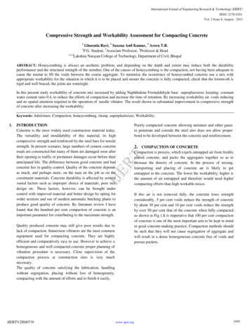
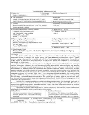
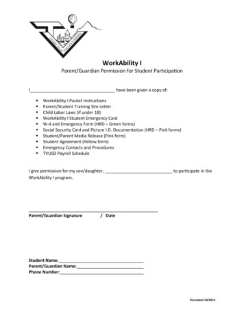
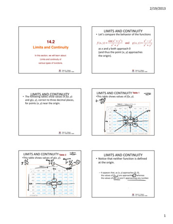
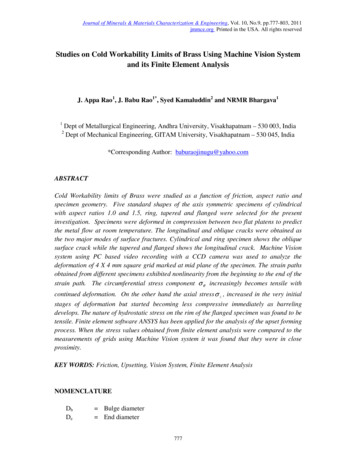
780J Appa Rao, J Babu Rao, Syed Kamaluddin and NRMR BhargavaVol.10, No.92. MATERIALS AND METHODSThe workability experiments were carried out on Brass. The material was procured fromlocal market of 2000 mm length X 25 mm diameter (Ф) size of hot rolled rods. The chemicalcomposition of the brass was given in Table 1.Table 1 Chemical composition of the Brass used in workability tests.Material% Copper% Zinc% TinOther element.Commercial Brass59.339.40.14------Standard specimens of cylindrical with aspect (H0/D0) ratios of 1.0, 1.5, flanged, tapered andring of standard dimensions were prepared from the procured rods of 25 mm diameter usinga conventional machining operations of turning, facing, drilling and boring. The machinedout specimens were shown in Figure 1. Geometries and specifications of specimens forworkability tests were given in Table 2. The average surface roughness at the flat and curvedsurfaces of the specimens was measured as 4 microns and 3 microns respectively. Surf testerwas used for the measurement. The upset tests were performed on all the specimens byplacing them between the smooth finished flat platens having a 4 microns surface roughness.Extreme care was taken to place the specimens concentric with the axis of the platens. Thetests were carried out at a constant cross head speed of 0.5 mm/min using a computercontrolled servo hydraulic 100 T universal testing machine (Fuels and Industrial Engineers(FIE), India– UTE model) to obtain different strain paths. The experimental set up of PCbased on line video recording system for grid measurement during upsetting was shown inFigure 2.Ring compression tests were conducted to determine the friction factor ‘m’ for a given set offlat platens. Standard ring compression samples of Outside Diameter (OD): Inside Diameter(ID): Height (H) 6: 3: 2 (24:12:8 mm) were prepared from the procured rods of 25 mmdiameter and were deformed slowly at a ram speed of 0.25 mm/sec on FIE makeCompression Testing Machine (CTM- Model-1M 30-0113, 200 T capacity).Figure 1: Photograph showing the cylindrical samples for upsetting, with differentgeometries of H0/D0 1.0, 1.5 and Ring, Tapered and Flanged
Vol.10, No.9Studies on Cold Workability Limits of Brass and its FEA781Table 2: Geometries and dimensions of specimens for workability )Diameter –Internal(mm)FlangeThickness(mm)2525----H/D ed37.525155CylindricalH/D 1.0Cylindrical
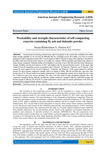
782J Appa Rao, J Babu Rao, Syed Kamaluddin and NRMR BhargavaVol.10, No.9Figure 2: Experimental set up of PC based on line video recording system for gridmeasurement during upsetting on 100T computer controlled servo hydraulic UTMA PC based system consisting of a video camera with an integrated digitizing capacity, 640 X480 pixels resolution, 256 colour full depth, 20 pictures per second shutter speed, mountedwith a magnifying lens was used to record the images of the upsetting process. A 4 X 4 mmsquare grid was marked at mid height of the standard specimen as shown in figure 3a. Onlinevideo images of grid were recorded during the deformation process till the crack initiationsite was observed. The distortions of grid from recorded images were analyzed offline. Theimages were selected at deformation steps of 5% using the software animation shop 3.0 andwere transported to paint shop pro 7.0 for further processing to get the enhanced noiselessimages of high clarity.The axial and the circumferential strains were calculated for each element from themeasurements obtained according to: ε z ln h i h 0 and wi w0ε θ ln Where h0 and w0 are the initial height and width of an element (Figure 3a) respectively, and hiand wi are the current height and width of the element, respectively (Figure 3b).
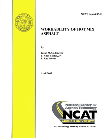
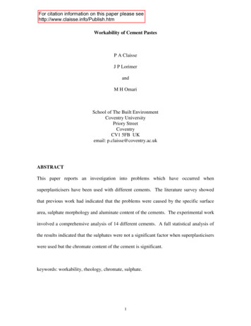
Vol.10, No.9Studies on Cold Workability Limits of Brass and its FEA783Figure 3: Schematic diagram of upset tests showing grids for strain measurements(a) Before deformation (b) after deformation3. RESULTS AND DISCUSSION3.1 Friction FactorThe decrease in internal diameter of the ring compression test was plotted against thedeformation on Male and Cockcroft [7] calibration curves in increments of 10% deformation.When these ring compression values were fit into calibration curves for the given set of dies,it was found that the friction factor ‘m’ with high finish dies was nearly equal to 0.30, asshown in Figure 4 .The same set of dies was used for upset tests also. Figure 5 shows thering compression samples before and after deformation.100%Decrease in Internal Dia80m 1.0m 0.4m 0.8m 0.6m 0.26040m 0.122000102030405060708090m 0.08-20-40m 0.04m 0m 0.02-60% DeformationFigure 4: Ring test calibration curves. Changes of the minimum internal diameter as afunction of the reduction in height.
784J Appa Rao, J Babu Rao, Syed Kamaluddin and NRMR Bhargava(a)Vol.10, No.9(b)Figure 5: Ring compression specimen (OD: ID: H 6:3:2)(a) Undeformed (b) 30% deformation3.2Finite Element Analysis of Ring Compression TestFinite element analysis of ring compression test was carried out for given frictional condition.Rigid-flexible contact analysis was performed for this process. For such analysis, rigid toolsneed not be meshed. The ring specimen was meshed with 10-node tetrahedral elements(solid 92 in ANSYS Library). Element size was selected on the basis of convergence criteriaand computational time. The program will continue to perform equilibrium iterations until theconvergence criteria are satisfied.The results of the FE analysis for ring compression shows that decrease in the average insidediameter against deformation has a variation of about 10% compared to experimental results.The variation might be due to non uniform friction in the later stages of deformation. Figure6 shows the undeformed and deformed mesh after 30% deformation of the FEA models ofring compression test (OD: ID: H 6:3:2) with friction factor (m) 0.30.(a)(b)Figure 6: Quarter FEA model of ring specimen (a) Undeformed (b) 30% Deformed
Vol.10, No.93.3Studies on Cold Workability Limits of Brass and its FEA785Load - Displacement CurvesFigure 7 shows the load - displacement curve for brass under friction factor ‘m’ 0.3 for allthe geometry of the specimens. The load requirement increased with increase in the axialdisplacement of the specimen, it was true for all the specimens. Further an increase in aspectratio from 1.0 to 1.5; the load required gets reduced for the same amount of deformation. Fora fixed diameter, a shorter specimen will require a greater axial force to produce the samepercentage of reduction in height, because of the relatively larger undeformed region [16].Present experimental results were in significance with the above discussion. As per thegeometry of the specimen is concerned, to deform the component, tapered specimen requiredmore load than ring and flanged specimens. The experimental loads reveal that geometry ofthe object also effect the load required for the deformation process.600.00500.00Load, KN400.00300.00200.00H/D 1.0H/D 010.0012.0014.00Displacement,mmFigure 7: Load – displacement curves for Brass in different specimen geometries with frictionfactor ‘m’ 0.30Figure 8 shows the representative plot of σ vs ε generated from the upsetting test datacarried out at slow speed with H0/D0 1.0 using mirror finished dies. This data was treatedto be material property [17] and used as input for finite element analysis. This curve was fitinto Holloman power law [18-24],* ( ε ) 0.285 for brass.σ K (ε )nresults the flow curve equation as σ 832
786J Appa Rao, J Babu Rao, Syed Kamaluddin and NRMR BhargavaVol.10, No.9700.00600.00True 050.100.150.200.250.300.350.400.450.50True Plastic StrainFigure 8: True stress vs true plastic strainThe specimens of various geometries which were subjected plastic deformation by upsettingup to the fracture initiation were shown in Figure 9. The longitudinal crack and oblique crackwere obtained as the two major modes of surface fractures. The mode of fracture dependsmainly on the state of stress and the state of strain, both of which in turn depend on thedegree of deformation and the slope of the strain path. The longitudinal crack is usuallyobtained when the axial surface stress is tensile, while the oblique crack is obtained when theaxial surface stress is compressive. Cylindrical and ring specimen shows the oblique surfacecrack while the tapered and flanged shows the longitudinal crack.H0 /D0 1.0H0 /D0 1.5(a)RingTaperedFlanged(b)Figure 9: Modes of surface cracking for different specimen geometries.a) Short (H0 /D0 1.0) and long (H0 /D0 1.5) cylindrical specimens(b) Ring, Tapered and Flanged specimens.
Vol.10, No.93.4Studies on Cold Workability Limits of Brass and its FEA787Experimental Strain and Stress analysis using Machine Vision SystemSurface strains, circumferential strain ( ε θ ) and axial strain ( ε z ) were evaluated for thegeometric mid-sectional grid of the specimens and the results were plotted in Figure 10.Homogeneous deformation corresponds to ideal condition, that is, deformation withoutfriction or barreling with a constant slope (α) of ε θ / ε z -0.5. The line with a slopeε θ / ε z -0.5 on ε θ vs ε z plot and which intersects the ordinates at ε θ 0.3 is an estimateof a fracture line for upsetting test performed on circular cylinders [25]. Though the intercept0.3 on the ordinate may be approximately correct for steels, it may differ for material tomaterial. Brownrigg et al [26] and H.A. Kuhn et al [27] reported these values of intercepts as0.29, 0.32, and 0.18 for the 1045 steel, 1020 steel and 303 stainless steel respectively. In thepresent work this intercept value was observed to be 0.07.The deviation of slope of the experimentally determined relationship between axial strain( ε z ) and circumferential strain ( ε θ ), from that corresponding to homogeneous deformationrepresents barreling. This deviation was less when the specimen - die interface friction waslow. In such cases ‘ α ’ was found to be independent of ε z throughout deformation andsignificant deviation was not observed from the ideal relationship for homogeneousdeformation. The strain paths obtained from cylindrical specimens with aspect ratios 1.0 and1.5 deviated from the line with slope – 0.5, which represents homogeneous deformation. Thedeviation increased as barreling developed. Flanged and tapered specimen geometries maybe regarded as specimens artificially prebulged by machining [28]. Flanged specimenexhibited a strain path similar to that found in axial tension. This is because very little axialcompression was applied to the rim during the circumferential expansion caused bycompressive deformation of the specimen. Tapered specimen gave strain path with slopesomewhere between tension and compression tests [17]. For ring specimen the flow of thematerial was dominant on the outer periphery compared to the inside periphery of the midsection, the deviation from homogeneous line was observed to be more than the solidcylinder of aspect ratio 1.5.It is interesting to note that all strain paths obtained from different specimens exhibitednonlinearity from the beginning to the end of the strain path. It is also observed that the slopeat a point on the strain path increases as that point moves toward the end of the strain path orthe fracture point. This means that at the fracture point, the incremental axial straincomponent (d ε z ) is almost zero, while the incremental circumferential strain component(d ε θ ) is very high. This change in the slope of the strain path has a great effect on the stressstate at the surface of the specimen. The curve fitting technique was used (because of thescatter in the experimental data for axial and circumferential strains) to obtain a smoothrelationship between the axial strain ( ε z ) and circumferential strain ( ε θ ). This relationshiprepresents the equations of the strain paths. Some of these equations for five strain pathsobtained from different specimens are given in Appendix A. The ends of the strain pathsrepresent the fracture points. Joining all the fracture points on all strain paths gives theworkability limit for the alloy considered.
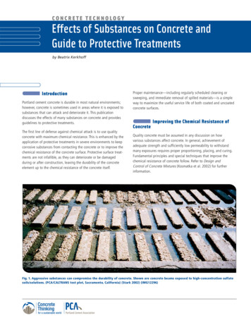
788J Appa Rao, J Babu Rao, Syed Kamaluddin and NRMR BhargavaVol.10, No.90.25Circumferential strain0.200.150.10H/D 1.0H/D 1.5RingFlanged0.05TaperedHomogeneous DeformationFracture 00Axial strainFigure 10: Circumferential strain ε θ as a function of axial strain ε z at the equatorialfree surface for Brass (with friction factor ‘m’ 0.30)Knowledge of the experimental plastic strain history allows experimental evaluation of stresscomponents during deformation (Appendix B). Effective stress ( σ ), and stress components,circumferential stress ( σ θ ) , axial stress ( σ z ) and hydrostatic stress ( σ H ) as a function ofeffective strain ( ε ) calculated from grid measurements of images obtained from MachineVision technique for brass of cylindrical samples aspect ratios of 1.0 and 1.5, and also forring, tapered and flanged were represented in Figure11. In an idealized situation of uniaxialcompression, the circumferential stress σ θ , is zero and the axial stress σ z is equal to the yieldstress, σ 0 . Under this condition the hydrostatic component of the stress, σ H would be equalto σ Z /3 and would always be compressive; a state of instability will never occur inhomogeneous deformation. Hence according to an instability theory of fracture ductilefracture will never occur in homogenous deformation. On the other hand if the frictionbetween the specimen and platens is more, the deformation departed from the homogeneouscase, which results barrel develops in the specimen. The tensile circumferential surface stresscomponent σ θ is non zero and the hydrostatic component of stress σ H become lesscompressive and in some cases tensile.The present results referring to Figure 11, the circumferential stress component σ θincreasingly becomes tensile with continued deformation. On the other hand the axialstress σ z , increased in the very initial stages of deformation but started becoming lesscompressive immediately as barreling develops. For unfractured specimens the axialstress σ z will always be compressive. However for the specimens where surface fracture
Vol.10, No.9Studies on Cold Workability Limits of Brass and its FEA789occurred both σ z and σ H stress components became less and less compressive asdeformation progresses and become tensile. The hydrostatic stress involves only pure tensionor compression and yield stress is independent of it. But fracture strain is strongly influencedby hydrostatic stress [29, 30]. Increase in friction constraint and decrease in aspect ratiocaused hydrostatic stress to be tensile and instability starts. As the hydrostatic stress becomesmore and more tensile, a state of tensile instability will occur. The transformation in nature ofthe hydrostatic stress from compressive to tensile depends on the geometry and size of thespecimen and the frictional constraint at the contact surface of the specimen with the dieblock.From the observation of Figure 11, hydrostatic stress as a function of effective strain, it wasconcluded that for the same amount of strain hydrostatic stress changes quickly fromcompressive to tensile under high friction conditions and for small aspect ratios. The natureof hydrostatic stress on the rim of the flanged specimen was tensile from the beginning of thedeformation while the axial stress on the rim was almost zero and the circumferential stresscoincides with the effective stress of the material. The nature of hydrostatic stress for ring,tapered specimens lie between the regions of cylindrical specimen with aspect ratio 1.5 andthe flanged specimens. For the brass, the extent of deformation from instability to fracture issmall. However this post instability strain to fracture can be increased by changing themicrostructure via proper heat treatment. Both normal and shear type of fracture wereobserved during metal experiments. Normal fracture was observed for the flanged andtapered samples due to presence of tensile axial stress at fracture, while shear fracture wasobserved for the rest of the specimens.800.00Stress,MPa600.00Effective Stress,MPa400.00Axial ic 00.00Effective Strain(a)0.250.300.35
790J Appa Rao, J Babu Rao, Syed Kamaluddin and NRMR BhargavaVol.10, No.9800.00600.00400.00Effctive StressStress,MPaAxial ic 400.00-600.00Effective Strain(b)800.00600.00Stress,MPaEffective Stress,MPa400.00Axial ic 00-600.00Effective Strain(c)0.300.350.40
Vol.10, No.9Studies on Cold Workability Limits of Brass and its FEA791400.00350.00300.00Stress,MPa250.00Effective Stress,MPa200.00Axial Stress,MPa150.00Circumferential Stress,MPaHydrostatic .30-50.00Effective ve Stress,MPa200.00Axial ic .00-200.00-300.00Effective Strain(e)Figure 11: Effective stress ( σ ), stress components σ θ , σ z and σ H as a function ofEffective strain ( ε ) for copper under low friction condition (Friction factor ‘m’ 0.30)H0/D0 1.0, (b) H0/D0 1.5, (c) Ring, (d) Flanged, (e) Tapered.(a)
792J Appa Rao, J Babu Rao, Syed Kamaluddin and NRMR BhargavaVol.10, No.94. FINITE ELEMENT MODELINGFinite element analysis of deformation behavior of cold upsetting process was carried out forcylindrical specimens with aspect ratios of 1.0 and 1.5 and also for ring, tapered and flangedspecimens. Since computers with high computational speed are now available in the marketat relatively cheaper cost, the time of computation is not a major constraint for solving theproblems of small sized 3-D models. Further, the tetrahedral elements can easily beaccommodated in any shape [31]. This reduces the number of iterations and steps to besolved. Owing to these facts the present problem was solved using 3-D model. The analysiscan also be extended to non axisymmetric problems using a full 3-D model. In the presentanalysis, quarter portion of 3-D model was considered with symmetric boundary conditions.Rigid-flexible contact analysis was performed for the forming process. For such analysis,rigid tools need not be meshed. The billet geometry was meshed with 10-node tetrahedralelements (solid 92 in ANSYS Library). Element size was selected on the basis ofconvergence criteria and computational time. Too coarse a mesh may never converge andtoo fine a mesh requires long computational time without much improvement in accuracy.The program will continue to perform equilibrium iterations until the convergence criteria aresatisfied. It will check for force convergence by comparing the square root of sum of thesquares (SRSS) of the force imbalances against the product of the SRSS of the applied loadswith a tolerance set to 0.005. Since the tolerance value in the program is set to 0.5%, thesolution will converge, only if the out of balance force is very small leading to more accurateresults.Material models were selected based on the properties of the tooling and billet materials.Due to high structural rigidity of the tooling, only the following elastic properties of tooling(H13 steel) were assigned assuming the material to be isotropic [32]. Young’s Modulus E 210 GPa and Poisson’s ratio υ 0.30. For billet material model selected is isotropic Misesplasticity with E 110 GPa, υ 0.375 and plastic properties obtained from Hollomon powerlaw equation. As the nature of loading is non-cyclic, Bauschinger effect could be neglectedand the non-linear data was approximated to piecewise multi linear with 10 data points. Careis taken that the ratio of stress to strain for first point equals to Young’s modulus of copper.The material was assumed to follow the Isotropic hardening flow rule. Suitable elasticproperties were also assigned for the material chosen for analysis. As the experiments wereconducted at room temperature, the material behavior was assumed to be insensitive to rate ofdeformation [33- 35].A 3-D, 8-noded, higher-order quadrilateral element CONTA 174 (of ANSYS library) that canbe located on the 3-D solid or shell elements with mid side nodes is used. It can bedegenerated to 3-7 node quadrilateral/triangular shapes. Contact surface was meshed withCONTA 174. TARGE 170 (of ANSYS library) is used to represent various 3-D targetsurfaces for the associated contact elements. The contact elements themselves overlay thesolid elements describing the boundary of a deformable body that is potentially in contactwith the rigid target surface, defined by TARGE 170 [36]. Hence a target is simply a
Vol.10, No.9Studies on Cold Workability Limits of Brass and its FEA793geometric entity in space that senses and responds when one or more contact elements moveinto a target segment element.5. VALIDATION OF FEA RESULTSFigure 12 shows the specimen before deformation. There was zero friction at metal-diecontact and no apparent bulging; the deformation can be treated as homogeneous, figure 13.The variation in the values of radial diameter at 50% deformation obtained from finiteelement analysis and calculated values from volume constancy condition is 0.7% [37]. Thissmall variat
Table 1 Chemical composition of the Brass used in workability tests. Material % Copper % Zinc % Tin Other element. Commercial Brass 59.3 39.4 0.14 ----- Standard specimens of cylindrical with aspect (H 0/D 0) ratios of 1.0, 1.5, flanged, tapered and ring of standard dimensions were prepared from the procured rods of 25 mm diameter using