Transcription
WorkmanshipChallenges for NASAMission HardwareJeannette PlanteNASA Workmanship Standards ProgramJune 23, 2010
Overview(1) Failure to apply NASA Workmanship Standards tocontractsJ-STD-001ES AdoptionNon-Standard ProcessesThe Packaging Design Dilemma(2) Electrostatic Discharge Charge Device Model (CDM)(3) Water Soluble Flux (WSF)(4) High Density Interconnect PCB’s(5) Column Grid Area Array Interconnect(6) Pb-free
Failure to apply NASA Workmanship Standards to contractsJ-STD-001ES AdoptionNon-Standard ProcessesThe Packaging Design Dilemma
NASA Workmanship StandardsRequired for all Programs, Projects, Contracts, and Subcontracts perNPD 8730.5 NASA Quality Assurance Program PolicyNASA-STD-8739.1, Workmanship Standard for Staking and Conformal Coatingof Printed Wiring Boards and Electronic Assemblies.NASA-STD-8739.2, Workmanship Standard for Surface Mount Technology.NASA-STD-8739.3, Soldered Electrical Connections.NASA-STD-8739.4, Crimping, Interconnecting Cables, Harnesses, and Wiring.NASA-STD-8739.5, Fiber Optics Terminations, Cable Assemblies, andInstallation.ANSI/ESD S20.20, Protection of Electrical and Electronic Parts, Assemblies andEquipment (Excluding Electrically Initiated Explosive Devices).These Standards contain our best known methods for avoiding pastassembly problems and defects. These best practices may not beavailable if suppliers are used who are not compliant with them.Compliance includes having certified operators and inspectors.
Examples of Problems from lack ofRequirements Flow-downCleanliness testing of finished boards not performedDemoisturizing boards prior to soldering and conformal coating notperformedTest specimens (aka “witness sample”) not produced for staking materialCrimp pull testing not performed or alternate acceptance values usedIncorrect ESD flooring measurement methods usedRequirements for Non-Standard Processes not addressed.Finding these problems during build of mission hardware is often too late(i) contractually and (ii) in the mission life-cycle, to resolve without residualrisk.How to establish known-good suppliers for Workmanship?When/how to develop up-and-coming suppliers who seek to serve NASAniche? Without putting mission hardware/schedule at risk
Adoption of J-STD-001ESNASA Workmanship is mandated to adopt industry voluntaryconsensus standards where practicable.NASA-STD-8739.2, Workmanship Standard for Surface Mount Technology.NASA-STD-8739.3, Soldered Electrical Connections.Will be replaced by J-STD-001ES, Space Applications ElectronicHardware Addendum to J-STD-001E Requirements for Soldered Electricaland Electronic AssembliesWorkmanship best practices may not be available if suppliers are usedwho are not compliant with J-STD001xS. Compliance includes havingcertified operators and inspectors.J-STD-001 Class 3 is not an acceptable substitute!!!See http://nepp.nasa.gov/index.cfm/5553Presentation on Transition to J-STD-001DS(scroll down to the last item on the page)
Examples of Changes/Challenges with theuse of VCS’s/J-STD-001xSNASA does not “own” J-STD-001xS. NASA cannot control inclusion orexclusion of any particular requirement. Space Committee considersmilitary and commercial space requirements as well as those of NASA.Change-over will drive “sudden” need for retraining/certifying of personneloutside of the normal two-year cycle. This may be have aschedule/cost impact across the industry.NASA does not drive pace of technology insertion and may not be able toprovide technology knowledge fast enough to develop appropriateassurance requirements for low-risk missions.Though DoD “adopted” J-STD-001 Class 3 in 2001 but has not required itwidely on contracts. DoD suppliers free to adopt “cafeteria plan”compliance with requirements. NASA adoption will challenge this.
Non-Standard ProcessesNASA-STD-8739.1, para 4.1.3NASA-STD-8739.2, para 4.1.3NASA-STD-8739.3, para 4.1.3NASA-STD-8739.4, para 4.1.3NASA-STD-8739.5, para 4.1.3“Nonstandard Processes, Materials, or Parts. When thesupplier intends to use processes, materials, or parts notcovered by this standard, the supplier shall document thedetails of fabrication and inspection, including acceptanceand rejection criteria, and provide the documentation alongwith appropriate test data to the procuring NASA Center forapproval prior to use (Requirement).”
What NASAMeansWhat SuppliersProvide“ processes, materials, or parts not covered by thisstandard and provide the documentation to the procuringNASA Center for approval prior to use ”Specialty High Temp SolderPb-free SolderWater Soluble FluxBall Grid Array, Micro BGAColumn Grid ArrayStacked MemoryChip-on-BoardStaked stacked partsCustom Cryogenic Cable HarnessesNotice provided for approval duringdesign process.Declarations in advance arenot being received.Design not being done byWorkmanship personnel.Design and assembly may be doneby two different suppliers.(See: “The Packaging Design Dilemma”later in this presentation)
What NASAMeansWhat SuppliersProvide“ the supplier shall document the details of fabrication andinspection, including acceptance and rejection criteria ”Evidence of an engineered processdesigned and optimized for thetechnologyRepeatable and controlledmethods used to monitor quality.Accept/reject quality criteriaSwap new technology into oldprocessAssume old quality methods workfor new technology.Use accept/reject criteria for oldtechnology to test/inspect newtechnology.Point to NASA WorkmanshipStandards quality methods andcriteria to show acceptability ofnew technology.
What NASAMeansWhat SuppliersProvide“ and provide the documentation along with appropriate testdata to the procuring NASA Center for approval prior to use ”Evidence that the intendedconfiguration (materials, geometries,quality level) is sufficiently reliablefor the intended NASA mission.Preferably life test data. Design bounds final productperformance. Engineered process achieves designand bounds quality variations. Quality methods bound qualityescapes.Raw material qualification dataHeritage statementsSuccessful completion of NASAWorkmanship Standards tests(regardless of their applicability)Claims that it is an in-house“standard process”
The Packaging “Design” Dilemma Workmanship Standards are implemented by operatorsand inspectors on a build-to-print basis. Quality organizations in NASA and NASA’s supply chainpresume that Workmanship is “taken care of” by theoperators and inspectors. Workmanship training is notrequired for packaging designers and process engineers. NASA Workmanship Standards contain design andprocess engineering requirements which are not controlledby operators and inspectors. IPC Standards will not contain design requirements. Who will capture and own Workmanship design andprocesses requirements? Center-level documents?
Electrostatic DischargeCharge Device Model
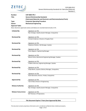
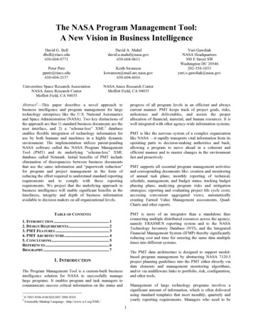
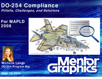
Overview(1) ESD Models Provide a way to characterize thesensitivity of components to ESD(2) The different ESD models simulate the differentenvironments experienced by electronic componentsduring the manufacturing process.(3) Parts and assemblies may beexposed to more than one typeof ESD event over themanufacturing and test lifecycle.Courtesy ESP Seattle Inc.
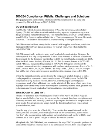
HBMMMmaturematureHBM Human Body ModelMM Machine ModelCDM Charged Device ModelVoltage discharged throughRC or RCL network createsdifferent total energyexperienced by the device.CDMevolving
White Paper 2: A Case for Lowering Component Level CDM ESD Specifications andRequirements, Industry Council on ESD Target Levels, March 2009
100X2000XCourtesy of JPLScott M. Hull NASA/GSFC4600x8600xCourtesy of JPLCourtesy of JPL
HBM safety methods have brought HBM & MMfailures down to 10% of failures encounteredindustry-wide.Role of CDM in failure count is now majority ( 90%)Examples of Sources of Threats (charge ordischarge path)HBMOperator Work bench MMPick and Place Machine Automatic Test Equipment CDM Device package charging/discharging Mate/De-mate of harnesses RF Signals (including cell phone signals)
CDM Challenges- Opportunities to use on-chip ESD protection reduced inhigh speed designs- Reduction in conductor widths on-chip result in highercurrent densities and thermal stress- Package capacitances in high pin-count designs increasepeak current during CDM ESD event.- Ionizers work on an HBM time scale and are not effectivefor mitigating rapid-pulse charging eventsSuppliers have been working to a 500V qualification level forCDM (peak current @ 16A).Industry position developing to reduce qualification level to250V (peak current @ 7A). increasing baseline risk
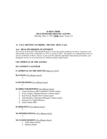
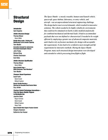
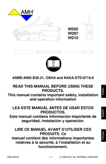
The area needed foron-chip ESDprotection againstCDM events @ 16Ahas becomeimpractical.TypicalCDM ChallengesGate damage susceptibility is scaling withfeature size.Both are 45 nm technology, LV is Vdd 1.1V, MV is Vdd 1.8VSource: White Paper 2: A Case for Lowering Component Level CDM ESD Specifications andRequirements, Industry Council on ESD Target Levels, March 2009
CDM ChallengesHSS high speed signalRC resistor/capacitorDTSCR diode triggeredsilicon controlledrectifierCapacitance must be reduced for high speed operation.The remaining budget for ESDS circuitry scales downwardproviding lower levels of ESD protection.Source: White Paper 2: A Case for Lowering Component Level CDM ESD Specifications andRequirements, Industry Council on ESD Target Levels, March 2009
CDM ChallengesPackage size causes an increase inCDM event current. Packagecapacitance charges triboelectricallyor inductively and then dischargesrapidly into the die during the CDMevent.
CDM Devices will be less robust to CDM event in the future and“old” practices may not be sufficient. Expert help will be needed to work through CDM safetysolutions. Complex and evolving event model. CDM safety measures may include new board materials,design rules, discharge steps during test, protection fromstray RF Technology drivers in high-speed, high pin-count devicesmake them more susceptible to CDM events. Suppliers will not “ESD harden” these devices HBM methods will not protect these devices
Water Soluble Flux
WSF entering mission hardware due to increased use inthe commercial sector (“It’s our standard process.”) Increased use in the commercial sector is to avoidproblems finding and using solvents needed to clean rosinflux. Active ingredient in WSF is organic or inorganic acidhowever they are pH-neutral. Halides often added toincrease activity level. NASA Workmanship Standards cleanliness test is notapplicable to pH-neutral contaminants. Designed to findhalides. (See: “Non-standard Processes”) No known screening test for pH-neutral flux contaminants.Tests are QCI type, typically used by process engineers notoperators; requires new equipment, knowledge. (See: “ThePackaging Design Dilemma”)
WSF contamination (unreacted and uncleaned flux, uncleaned halides)has been root cause of failures in commercial production. Failures are being encounteredin commercial uses indicatingneed to understand processfactors better. Rosin flux mayhave provided more “forgiving”system (wider quality window). Cleanliness risk mitigationmethods are not well understoodand therefore not standardized(and not tuned for NASAmissions). Failure modes are electricalshorts through dendrites, metallicsalts, electrolyteCourtesy: ForesiteMetallic salt deposits may bepermanent causing entireassemblies to be scrapped.
At GSFC one project was using WSF in 2008. In 2010 thereare now five. Not being used at other NASA Centers (yet?) Five out of five users have had solder joint voiding to levelnot “normal” for a rosin process. Workmanship does not have a clear policy on acceptablelevels of voiding. Acceptability is strongly tied to thermalcycling environment. IPC points to “engineering” to refereethe acceptability of voids.
High Density InterconnectPrinted Circuit Boards
In 2008 a GSFC project encountered a printed wiringassembly with a PCB that was failing batch-based qualityinspections. Extensive engineering and quality attention to this boardfound that: HDI features such as buried vias, micro-vias, and a high layer count made itvery complex to manufacturer The system supplier did not have a PCB supplier who could identify andcontrol the critical processing parameters
In December 2009 the IPC hosted a government-industrysymposium on the concerns of the US PCB industry.A major concern is a loss of the ability of US firms toleverage off of high-volume commercial business to fundstate-of-the-art (SoA) technology knowledge (process andquality R&D) for their low-volume customers (Mil and Space).Though device suppliers require SoA features, PCBmanufacturing capability is lagging and showing up as qualitydefects.Courtesy: Coretec
Interconnect Stress Testing (IST) should be investigated forstandard use by NASA in addition to coupon analysis.Courtesy: PWB Interconnect Solutions Inc.Resistive heating and sense circuits built into PCB couponscan be used to rapidly perform thermal cycling QCI testing.Developer has demonstrated good correlation between fieldfailures and IST test failures.
Area Array Interconnect
Column Grid Array Area Array Interconnect knowledge has been developed for many yearsby NEPP, IPC, CALCE, CAVE, others. Strong dependency between reliability goals and processingparameters slowed progress on standardizing quality rules. IPC 7095, Design and Assembly Process Implementation for BGAs,October 2004:- Is a guideline document- Does not directly address CGA’s IPC J-STD-001ES now addresses BGAs and CGAs:7.5.14 Surface Mount Area Array Packages PCB design rules not addressed by J-STD-001ES. Pursuing PCBplacement rules on mirroring, rework keep-out zone, and pad design forinclusion in IPC-2222, Sectional Design Standard for Rigid OrganicPrinted Circuit Boards.
Column Grid ArrayIPC J-STD-001ES CGA Rules:- No missing columns (except corners which may be intentionally missing)- Minimum electrical clearance limits are not violated- Full solder fillet for viewable columns. Use Xray for those which cannot beviewed.Additional Rules used by GSFC (Center Level):- Process capability audit required- Lead co-planarity- Board flatness- Mechanical analysis of board design for thermal and mechanical robustness- No part mirroring- No solder-mask defined pads- No shared vias- Corner staking is required- Applicable NASA Workmanship Standard requirements (8739.2)- Verification of sufficient solder volume- Visual verification of part placement- Qualification testing of representative units (to show line capability)
Pb-Free
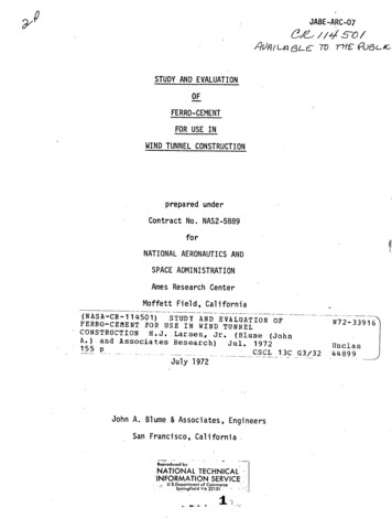
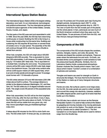
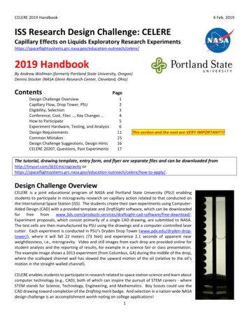
-RoHS Movement in Europe in mid 1990’s-solderable surfaces and solder itself must be Pb-free-Worldwide suppliers offer pure tin as alternative-Researchers and users are reminded of the tin whisker hazard-Industry searches for new solder SnBi57Ag1-New formulations come with known and unknown risks-Sensitivity to physical shock-Some test methods do not “translate”-Higher processing temperatures can affect boards and parts-Assemblies may mix solders-Logistics may not be set up to identify Pb-free materials-Solder joints have “dull” appearancea.SnPb solder, b. Pb-free solder, Source: Lead Free Surface MountTechnology, Ian Wilding, Henkel Technologies, 2005a.b.
Quality Assurance Requirements TraceabilityNPD 8730.2, NASA Parts PolicyAttachment A: Criteria to Mitigate Risks Associated with Lead-Free Solder andSurface Finishes(paraphrased)a. Sn-Pb shall be used whenever possible. Use of Pb-free ( 3% Pb) may beused by special approval on technical need and risk mitigation.b. A GEIA-STD-0005-1 Pb-free control plan is required which addresses:design considerationstest & qualification requirementsmarking & identificationrisk mitigationmanufacturing process controlsquality inspection & screeningmaintenance & repairapplication uniqueness'sc. GEIA-STD-0005-2 “2C” level whisker risk mitigation. “2B” level allowed inspecial circumstances and with PCB approval.d. Use of Pb-free Sn-based solders and surface finishes, in applications below13.2oC, shall be assessed for the risk of the damaging effects of tin pestformation (allotropic phase transformation of tin).
Quality Assurance Requirements TraceabilityJ-STD-001DS.1 Joint Industry Standard, Space Applications ElectronicHardware Addendum to J-STD-001D Requirements for SolderedElectrical and Electronic Assemblies1. Scope is surfaces to be soldered and solder used.2. The following are specifically prohibited withoutmeeting additional requirements: Pb-free tin platings or metallization on external surfaces ofEEE parts, mechanical parts, including on parts inside ofmodules (e.g. MCM, Relays) Pb-free solder alloy except Sn96.2Ag3.7
Quality Assurance Requirements TraceabilityCont. J-STD-001DS.13. The cases above are allowed only with a USER approved leadfree control plan (LFCP) which accomplishes:a. Re-plating or hot solder dip replacement of Pb-freesurfaces with SnPb -orb. Minimum of 2 other risk mitigation methods employed4. LFCP shall ensure functionality of hardware in intendedapplication w/r/solder, platings, soldering processesa. Document every incidence of useb. Minimum of two mitigation methodsc. Document special design requirements, processes,testing, inspections, marking, repair
LFCP Template InstructionsTemplate has same section numbers and headings as GEIA-STD-0005-1.Green Shading : short reminder of requirement statement from GEIA-STD-0005-1, removedby authorBlue font:fill in information on materials, reliability, configuration management,procedures, etc.The instructionsassume that the Plan author has access to theinformation, either through personal knowledge, or through other knowledgeablepersonnel. can “standard” methods be provided ?[Supplier name]:fill in the name of the organization responsible for implementing the Leadfree Control Plan[LFCP]:fill in supplier’s formal name or doc number[Bold Italicized ] :fill in additional or custom informationPrior to review, remove the 1st section break and alltext on pgs i through iv and remainder will be theLFCP.
LFCP Template1.2.3.4.5.6.7.8.9.Cover PageTable of ContentsConfiguration Management tableForward: 2 examples given, choose one or make your ownPurpose and Applicability: fill in LFCP name, fill in supplier nameExclusions: describe exclusions from scope of the planReferences: GEIA providedTerms, Definitions and Acronyms: 39 IPC and GEIA terms includedObjectives: author is instructed to address the following:-Reliability: how will this be demonstrated?Configuration control and product identificationCaveats: remaining risks and limitations of useDeleterious effects of tin whiskers: how mitigated?Repair, rework, maintenance, and supportHow to prefer suppliers whoare using this approach?
Summary (1 of 2)(1) Failure to apply NASA Workmanship Standards to contractsJ-STD-001ES AdoptionNon-Standard ProcessesThe Packaging Design DilemmaIneffective attention to established Workmanship requirements during vendor selection,product design, and process engineering are very difficult to overcome during the buildcycle. New packaging design standards are needed to capture design rules formerly in theNASA Workmanship standards.(2) CDMESD safety techniques for CDM events need development. These methods may includenew circuit and board design and test rules. High speed performance will continue to drivechip designs to be less CDM-robust.(3) WSFNASA Workmanship Standards methods are not fully effective for pH-neutral flux and do notaddress voiding. NASA needs to develop new assurance rules for use of WSF.
Summary (2 of 2)(4) High Density Interconnect PCB’sLow-volume producers of this technology, who service t
NASA-STD-8739.2, Workmanship Standard for Surface Mount Technology. NASA-STD-8739.3, Soldered Electrical Connections. Will be replaced by J -STD-001ES, Space Applications Electronic Hardware Addendum to J -STD-001E Requirements for Soldered Electrical and Electronic Assemblies. Workmanship