Transcription
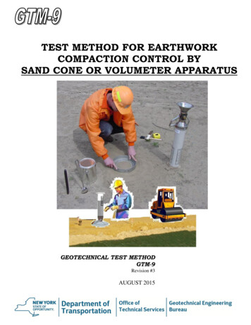
TEST METHOD FOR EARTHWORKCOMPACTION CONTROL BYSAND CONE OR VOLUMETER APPARATUSGEOTECHNICAL TEST METHODGTM-9Revision #3AUGUST 2015
GEOTECHNICAL TEST METHOD:TEST METHOD FOR EARTHWORK COMPACTION CONTROL BYSAND CONE OR VOLUMETER APPARATUSGTM-9Revision #3STATE OF NEW YORKDEPARTMENT OF TRANSPORTATIONGEOTECHNICAL ENGINEERING BUREAUAUGUST 2015EB 15-025Page 1 of 13
TABLE OF CONTENTS1.SCOPE .32.SUMMARY OF METHOD .33.EQUIPMENT.34.EQUIPMENT CALIBRATION .54.1Sand Cone Apparatus Volume Correction .54.2Sand Calibration Factor .54.3Volumeter .65.TEST PROCEDURE .75.1Test Location Data .75.2Testing and Sampling .75.3Determination of Plus ¾ in. (19 mm) Material and Moisture Content .95.4Control Density .11APPENDIX .13A.B.C.D.E.EB 15-025Sand Cone Apparatus Drawing SM 1685 . A-1Density Cylinder Drawing SM 1563. A-2Sand Density Calibration - Form SM 85 R1 .B-1Density Correction Curves Plus 3/4" (19 mm) MaterialSpecific Gravity 2.60 - Figure 1 .C-1Compaction Control Curves - Family 1 and Family 2 . D-1Field Compaction Sheet - Sand Cone or Volumeter Apparatus Form SM 417b . E-1Page 2 of 13
1. SCOPEThis test method describes the procedure for determining the in-place density and moisture ofearthwork through the use of a sand cone or volumeter apparatus. This method may be used inconjunction with either the Standard (AASHTO T-99) or Modified Proctor (AASHTO T-180)Density Test for determining the percent of Maximum Density.The details included in this test method are for use with the Standard Proctor Test.2. SUMMARY OF METHODThe test consists of the following steps which are explained in the test procedure:- Determining the Wet Density- Determining the Moisture Content- Calculating the Dry Density- Determining the Maximum Density- Calculating the percent of Maximum Density3. EQUIPMENTa.Sand Cone Apparatus: The sand cone apparatus consists of a container for thecalibrated sand; a conical, stopcock-controlled outlet; and a base plate. The base ofthe conical outlet shall have a nominal interior diameter of 6 in. (150 mm), and shallbe flared flat to fit the base plate. The base plate and container are matched andfitted; they are not to be interchanged with other units. The sand container shall becapable of holding no less than 8 lbs. (3.6 kg) or 1 ft.3 (0.028 m3) of calibrated sand.See Geotechnical Engineering Bureau Drawing No. SM 1685 (Appendix A) for anacceptable apparatus.Volumeter: The sand cone displacement volumeter with its matching base platemay be substituted for the sand cone apparatus. The volumeter has been calibratedto read volume directly as opposed to the sand cone apparatus which requires aconversion from weight to volume.b.c.d.EB 15-025Density Cylinder: 1/30 ft.3 (944 cm3) volume, in accordance with AASHTOStandard Density Test T-99 or Geotechnical Engineering Bureau Drawing No. SM1563A (Appendix A).Rammer: Refer to AASHTO T-99 or T-180.Scale: Minimum of 30 lb. (13.6 kg) capacity to weigh directly to the nearest 0.01 lb.(5 g).Page 3 of 13
e.f.g.h.i.* j.* k.* l.* m.n.* o.p.* q.r.s.t.Balance: Approximately 1600 g capacity, to weigh directly to the nearest 0.1 g.Steel Straight Edge: 9 to 12 in. (230 mm to 300 mm).Gas or Electric Stove.Sieve: ¾ in. (19 mm).Pail: 10 qt. (9.5 L) size or larger.Knife: Butcher.Hammer: 1 lb. (0.5 kg) minimum weight.Chisel: 1 in. (25 mm) blade width by 9 in. (230 mm) length.Skillet: 12 in. (300 mm) diameter.Spoon: Basting type.Spatula: 6 in. (150 mm) length of blade.Cans: Friction top with covers, 1 gal (3.7 L) size.Pans: 24 in. (600 mm) square and 3 to 4 in. (75 mm to 100 mm) high.Tares: Numbered cake pans or pie plates for moisture content determinations.Paint Brush: 2 in. (50 mm) size.Calibrated Sand: Clean dry sand.(a) Standard Ottawa Sand;or (b) Washed sand passing the No. 20 (0.85 mm) sieve and retained on the No. 40(0.425 mm) sieve;or (c) Flint Shot Grade, Size 2Q.u.Calibrated Container: Having a capacity of 0.1 ft.3 (2832 cm3), an inside diameterof 6 in. (150 mm) and an inside height of 6.1 in (155 mm): used for calibrating thesand.v.Compaction Control Curves: Family 1 and Family 2, (3 sheets) dated 02/28/77,see Appendix D.w.Plus ¾ in. (19 mm) Correction Curve: A curve for a specific gravity of 2.60 isincluded. See Appendix C. Curves for other specific gravities are available from theRegional Geotechnical Engineer.x.Form SM 417: Field Compaction Sheet, sand cone or volumeter apparatus(Appendix E).* The equipment annotated by asterisks are not essential, but are considered desirable.EB 15-025Page 4 of 13
4. EQUIPMENT CALIBRATION4.1Sand Cone Apparatus Volume CorrectionA portion of the sand released from the sand cone apparatus during the test remains in thecone. The apparatus volume correction is the weight of this material. This correction valuemust be determined for each sand cone apparatus and is usually furnished by the RegionalGeotechnical Engineer. Form SM 85 R1 – Sand Density Calibration (Appendix B), may beused for the sand cone apparatus volume correction and the sand calibration factor (Section4.2). It is determined in the following manner:-Avoid all vibrations of the equipment while filling or emptying the apparatus.On a level surface, fill the apparatus with sand through the cone at a uniform rate untilsand stops.Close the stopcock carefully and pour off the excess sand remaining in the cone.Weigh the filled sand cone apparatus.Invert the sand cone apparatus on the base plate on a smooth and level surface such as atable.Open the stopcock and allow the sand to flow out of the apparatus. Do not allow anysand to spill outside of the cone during this operation.Close the stopcock after the flow of sand has stopped.Remove and weigh the sand cone apparatus.The difference in weight is the Apparatus Volume Correction – lbs. This value will remainconstant for each apparatus unless the cone subsequently becomes dented or the calibratedsand changes. If the cone becomes dented or the calibrated sand changes, the apparatusvolume correction must be re-determined.4.2Sand Calibration FactorThe sand calibration factor is the loose unit weight of the calibrated sand. The RegionalGeotechnical Engineer will normally furnish this value. It is determined in the followingmanner:-Weigh a filled sand cone apparatus.Place the matched base plate over a calibrated container of known volume. Invertthe filled sand cone apparatus on the base plate.Open the stopcock until the sand tops flowing.Close the stopcock.Weigh the sand cone apparatus.Subtract the second weight and the apparatus volume correction from the first(filled) weight.Divide the difference in weights by the known volume of the calibrated container.This value is the Sand Calibration Factor – pcf. It should remain constant.EB 15-025Page 5 of 13
The sand calibration factor and the apparatus volume correction must be for the calibratedsand actually being used for the test. Any time the sand supplied changes or there is anyreason to suspect a difference in material, then both the Apparatus Volume Correction andthe Sand Calibration Factor must be re-determined.4.3VolumeterThe volumeter and matching base plate have been calibrated. No additional calibration isrequired even if the appearance of the sand changes.To fill the volumeter:a).Make sure the volumeter is empty.b).Set the volumeter with the stopcock open on a firm, level area with the cone endup.c).Fill the plastic container completely by pouring the sand into the cone. Keep thecone full until the sand stops flowing into the container.d).Close the stopcock carefully and pour off the excess sand remaining in the cone.e).If the volumeter is subject to movement or vibration during the filling operation orthe closing of the stopcock, remove all the sand and start over.f).At no time should the cone portion of the volumeter be removed from the cylinder.Removal or displacement by tightening or loosening of the cone will affect thecalibration.Keep the reserve container of sand covered (while not taking sand from it) to keep the sandfrom picking up moisture from the air.As the volumeter is handled and transported, the sand will compact, and its level within thevolumeter will drop.Do not add more sand. The measurement of the volume of the hole by the volumeter isbased on loose volume of sand.Damaged volumeters and/or base plates should be immediately removed from service.Volumeters which have been supplied by the Geotechnical Engineering Bureau and becomedamaged shall be returned to the Bureau.EB 15-025Page 6 of 13
5. TEST PROCEDUREForm SM 417b is used for recording the compaction test data. Refer to this form in Appendix E.Enter the required project information at the top of the form. Gs – Bulk Saturated Surface Dry shallbe assumed to be 2.60 unless otherwise directed by the Regional Geotechnical Engineer.Form SM 417b uses US Customary Units (lbs.) for recording the larger weights (sand & apparatus,sand, Plus ¾ in. (19 mm) Material, etc.) and International System of Units (g) for recording thesmaller weights (soil & tare, tare, etc.).5.1Test Location DataLINES5.21-Date of Test.2-Test No.: Tests for a project shall be numbered as required by MURK.3-Station of Test: The location of the test should be determined accurately.4-Offset: The location of the test should be determined accurately.5-Location: The required percent of maximum density for the materialdepends on its location. Indicate whether the test is performed in theembankment, in the subgrade area, at a structure location or at another areawith specific compaction requirements.6-Soil Type: Briefly describe the material tested so that the appropriateFamily of Compaction Control Curves is used.Testing and SamplingThe sand cone apparatus is used to determine the volume of the test hole. Fill the apparatuswith calibrated sand and weigh it. The scale and balance must be leveled and properlyadjusted before any weighing are made. The volumeter may also be used for thisdetermination, in which case weighing is not necessary.Remove all loose and disturbed material at the test location. Level a small area and set thebase plate firmly in place. Dig a hole through the opening in the plate, approximately equalin diameter to the hole in the base plate, and to a depth of approximately 6 in. (150 mm).The desired volume of the hole is about 0.1 ft.3 (2832 cm3). The volume should never beless than 0.06 ft.3 (1700 cm3). The hole should be dug rapidly and all removed materialimmediately placed in a previously weighed friction top can. The can should be covered tokeep moisture loss from the sample to a minimum. Any material loosened during thedigging operation should be removed from the hole and placed in a friction top can. Thecalibrated sand must completely fill the hole. Care should be exercised to avoidEB 15-025Page 7 of 13
undercutting of the base plate and abrupt projections of embedded materials into the hole.Projections inhibit the proper filling of the hole with the calibrated sand which causes errorsin the determination of the hole volume. If any of the above criteria are not met, the test isvoid.Set the sand cone apparatus or volumeter on the base plate over the hole. Open the stopcockto permit the sand to flow into the hole. Traffic and equipment in the vicinity of the test areashould be stopped while the stopcock is open. Vibrations will compact the flowing sand inthe hole resulting in an incorrect test value. After the sand stops flowing, close the stopcockand remove the apparatus.When using the sand cone apparatus weigh the apparatus with the sand remaining in it. Donot refill the sand cone apparatus until after this weight has been recorded.If the volumeter is used, hold the closed volumeter vertically with the cone end up. Invertthe volumeter momentarily and return to the original position. Gently shake (do not jar) theapparatus just enough to level the sand. From the scale indicators on the container, read thetop surface of the sand to the nearest 0.001 ft.3. Repeat 2 times. Record the average of the 3readings on Line H of the Compaction Control Work Sheet. (No individual reading shouldbe greater than 0.001 ft.3 more or less, than the average of the 3 readings.Note: The volumeter must be emptied of all remaining sand before it is refilled for anothertest.Additional soil may be required for use later in the test procedure. This soil shou
b. Density Cylinder: 1/30 ft.3 (944 cm3) volume, in accordance with AASHTO Standard Density Test T-99 or Geotechnical Engineering Bureau Drawing No. SM 1563A (Appendix A). c. Rammer: Refer to AASHTO T-99 or T-180. d. Scale: Minimum of 30 lb. (13.6 kg) capacity to weigh directly to the nearest 0.01 lb. (5 g).