Transcription
Infusion PumpSP 800Service ManualContect MedicalSystems . CO.LTD
ForewordIntroductionThis Operator's Manual provides a detailed introduction of the hardware components, installation,dismantling, testing and troubleshooting of this product and its parts, which may effectively helprepair staff handle commonly seen problems. It does not provide in-depth information on thestructure and design of the product. If you experience problems that cannot be solved, please contactour after-sale service department.Information in this Operator's Manual is based on a fully configured product, some of which maynot be applicable to the product you're repairing. If you have any questions, please contact our aftersale service department.Before carrying out any repair work, please ensure that you can properly repair the product bycarefully reading and fully understanding the content of this Operator's Manual. This way, damageto the product or physical injuries may be avoided.For use by:Professional biomedical engineers responsible for the maintenance of this product, authorizedrepair staff or after-sale service representatives.Version InformationThe version number of this Operator's Manual may be updated without notice at any time due tochanges in software or technical specifications. The version information of this Operator's Manualis as follows. Version No.: 2.0 Time of Publication: 2013-11I
ContentsChapter 11.1Safety . 1Safety Information . 11.1.1 Dangers . 21.1.2 WARNING . 21.1.3 CAUTION . 31.1.4 NOTE . 31.2Chapter 2Equipment Symbols . 4Design . 52.1Description . 52.2System decomposition . 52.3Hardware configuration. 72.3.1 Control Board . 82.3.2 Pump body . 92.3.3 Control Board . 102.3.4 Bubble pressure board . 112.3.5 Door-opening detection board . 122.3.6 Drop rate sensor . 12Chapter 33.1Testing and maintenance . 13Description . 133.1.1 Testing report. 143.1.2 Recommended frequency . 143.2Visual inspection . 153.3Startup test. 153.4Infusion Flow test . 163.5Pressure sensor test . 173.6Battery performance test . 183.7Electrical safety test . 193.7.1 Housing leakage current test . 203.7.2 Patient leakage current test . 203.8Chapter 4Cleaning and Disinfection . 21Common failures and Troubleshooting . 234.1Overview . 234.2Components replacement . 234.3Common failures and Troubleshooting . 241
Chapter 5Maintenance and Disassembly . 275.1Tools . 275.2Preparation for disassembly . 275.3Disassembly procedure . 285.3.1 Separate the front and rear housing . 285.3.2 Disassembly of Control Board . 305.3.3 Removal of the Pump body . 315.3.4 Remove the Sensor board and Pressure sensor . 355.3.5 Change the battery. 36Chapter 66.1Components. 37Host components . 376.1.1 Main parts lists . 386.2Pump Body Assembly . 392
Chapter 1 Safety1.1 Safety InformationThe safety statements presented in this chapter refer to basic safety information that theoperator must pay attention to and abide by during maintenance operations of the infusionpump. There are additional safety statements in other chapters or sections, which may be thesame as or similar to the following, or specific to particular operations.DANGERS Indicates an imminent hazard that, if not avoided, could result in death, seriousinjury or damage to product/property.WARNING Indicates a potential hazard or unsafe maintenance practice that, if not avoided,could result in death, serious injury or damage to the product/property.CAUTION Indicates a potential hazard or unsafe maintenance practice that, if not avoided,could result in minor personal injury, product malfunction or damage toproduct/property.NOTE Provides application tips or other useful information to ensure that you achievebetter maintenance of the product1
1.1.1 DangersDANGERS The infusion tube must be installed straight and level in the bottom of the grooveon the infusion pump.1.1.2 WARNINGWARNING Only authorized professional maintenance technicians can disassemble theInfusion pump; Pump maintenance and upgrades must be carried out bymaintenance technicians trained and licensed by the manufacturer. To prevent fire or explosion, do not operate this infusion pump in the presence ofanesthetic, flammable or explosive materials. This infusion pump belongs to Class II (type of electric shock protection); thesupplied Type I power cord PE earth terminal should not be used as groundprotection and functional earthing. The packaging materials must be disposed of in compliance with local laws andregulations or the hospital policy on waste management. They must be kept outof the reach of children.2
1.1.3 CAUTIONCAUTION Electromagnetic fields may influence the performance of the infusion pump.Therefore, equipment or devices used in the vicinity of the infusion pump mustmeet the EMC standard. Mobile phones, X ray and MRI equipment are allpotential interference sources because of their high-intensity electromagneticradiation. Avoid exposing this infusion pump to high-pressure sterilization or chemicalmaterials. Before the infusion pump is connected to the power supply, make sure thevoltage and frequency of the power supply comply with the label on the pump orthe specific requirements outlined in this Operator’s Manual. In the maintenance process, please pay attention to protect the pump fromdamage from drops, impacts, violent shaking or other external mechanicalforces.1.1.4 NOTENOTE For detailed operating instructions and other information about the infusionpump, please refer to the Operator's Manual. This Service Manual describes all the settings and functions of the infusionpump in its most complete functional configuration. The infusion pump you arehandling may not have some of the settings or functions described herein. Do not insert devices that are not specified by the manufacturer into the dataports.3
1.2 Equipment SymbolsAttention! Refer to themanualClass II equipmentIP21Class BF deviceSplash-proofAlternating current powersupply (AC)Direct current powersupply (DC)Batch numberSerial numberDate of manufactureManufacturerElectronic equipment:dispose of separately toavoid polluting theenvironmentWireless transceiverUp or increase valueDown or decrease valueConfirmSetStopCancel alarmStartBolusClearSelectTurning on the pumpTurning off the pumpDecimal pointProtect from rain duringtransportFragile item, handlewith careKeep upright duringtransportMaximum stack heightwithout additionalpackaging:layers complies with EU directive MDD 93/42/EEC andCE marked 5product,annex I thereof.4
Chapter 2 Design2.1 DescriptionThis infusion pump is for use in wards, operating theaters, and observation rooms foraccurate and continuous infusion to patients.2.2 System decompositionThe system is decomposed according to Machinery, Hardware and Software three aspects,with the composition chart as follows:SystemMachineryHardwareFront housingassemblyPumpassemblyRear housingassemblySoftwareControl BoardSystem softwareBatteryDriver softwareSensor BoardBubble pressure boarddriverDoor-openingdetection boardDrop sensorDrop sensor5
System Board connection diagram is as follows:Door-openingPressuredetection boardsensorDisplay screenFPC1P GatePYL 1Flash2Control Board1QpylP TX1CN2Bubble pressureboardP oudspeaker6Stepper motorBatteryDropsensor
2.3 Hardware configurationFunctional block diagram:Stepper Driver moduleControl module3.3V/5VCurrent supply5V CurrentsupplySerialCommunicationBubble pressureboardThe core of the system is the Control Board. Screen display and power supply is carried out byControl Board; measurements and status information for each module are sent to the Controlmodule after treatment in the Driver module, and finally displayed on the computer screen byControl Board; Control Board is also responsible for controlling Buzzer and Status indicatorlights. Current supply for all the modules are provided by the Power Board; the Driver moduleis also responsible for driving of the motor, measurement of each sensor and integratedtreatment of the status information.7
2.3.1 Control BoardControl Board is information integration of the entire system, providing resources and supportfor the entire system. It controls the LCD, keypad input, buzzer sounds and set the parameter'sstorage capabilities.2.3.1.1 Functional block diagramSRAMBuzzerMCUDisplayRun LEDKeysEEPROM5V3.3VLogical gate circuitSerial port1: Power BoardSerial port2: ZIGBEEwireless module2.3.1.2 Function introduction Control Board makes communications with the Power module or the ZIGBEEwireless module on the Control Board through the serial ports of the logical gatecircuit extension modules; Control Board provides display information for the display screen, and detects keypress to implement user interface; Control Board controls the Buzzer to realize the function of alarm tone andkey tone; Control Board controls running of the indicator light via the logical circuit; SRAM realizes data staging and procedures operation, and EEPROM serves asmachine configuration memory.8
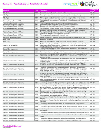
2.3.2 Pump bodyPump body device is the power provider of the whole system and the power source for liquidtransportation. During work, the stepper motor driven camshaft rotation makes the pumpmoving up and down according to a certain order and motion law, such as waves to squeezethe intravenous infusion tube, and let the fluid inside make a directional flow at a certain speed.Functional schematic diagramTubePump tablet9
2.3.3 Control BoardControl Board synthesizes the functional information detected from Bubble pressure board andthen sends it to CPU, and it also sends an information to drive the stepper motor. Control Boardalso converts the input power (including mains and battery) into the power required for eachboard, and supports the battery charging simultaneously.2.3.3.1 Functional block diagram5VLDOACInput3.3VAC/DCSerial portMCUSwitchingpower supply12VChargingCircuit7.4VLogicalgate circuitBatteryMotorDetectioncircuitStepper Enable input10
2.3.3.2 Function introductionAfter the AC input enters Control Board, it changes into 12V DC voltage first after passing asafety power supply modules, then the DC voltage serves as the primary input for DC/DCconverter and the charging circuit, to charge the lithium-ion battery, and also after 5 v DC/DCconverter, 3.3V LDO, 18.9V boost DC/DC converter circuit transformation it turns to be DC5V, 3.3V, and 18.9V respectively.Power supply module, in addition to completion of the power supply function, the on-boardMCU is also responsible for integrated synthesis of the measurement from the sensors and thestatus messages to send to the Control Board. Besides, it controls operation of the stepper motoraccording to orders from the Control Board.2.3.4 Bubble pressure boardBubble pressure board provides detection functions for bubble, blocking, and the handle dooropening detection. It detects air bubbles according to ultrasonic attenuation of differentmaterials, and detects the degree of blocking using a pressure sensor.2.3.4.1 Functional block diagramHandle dooropeningdetectionUltrasonicemission circuitUltrasonic receptioncircuitMCU5V InputPressure amplifying circuitSend toPower BoardPressureinformationoutput2.3.4.2 Function introductionCPU on the ultrasonic pressure board processes the signals collected from the door-openingdetection according to the ultrasonic circuit and sends it to the MCU on Power Board;Pressure amplifying circuit amplifies weak voltage signal from the pressure sensor and sendsit to the Power Board.11
2.3.5 Door-opening detection boardIn the Door-opening detection board lays a micro switch, the closing status of which is affectedby the handle status. So by detecting how much the micro-switch is closed you can know thehandle status at this time.2.3.6 Drop rate sensorFunctional block diagram:IR reception circuitIR emission circuitPowerBoardThe Drop rate sensor is fixed on the liquid filter; the measuring methodology is that when awater droplet drops in the liquid filter, it will block the rate sensor from receiving of infraredlight; using the pulse signals generated by different intensities of infrared light reception forthe conversion from drug liquid droplets frequency into infusion flow rate. Besides, this signalalso offers actual transfusion condition of infusion pump, which can detect whether there isliquid leakage situation.12
Chapter 3 Testing and maintenance3.1 DescriptionTo ensure long-term stability of the infusion pump, maintenance personnel must provide it withregular inspection, maintenance and testing. In this chapterYou will understand the basic testing methods for the infusion pump as well as recommendedtesting frequency and testing tools. Maintenance personnel should choose proper testing toolsand carry out inspection and testing according to the actual needs.The tests and testing methods provided in this chapter are mainly used to verify whether theperformance of the infusion pump achieves its specifications. If test results do not meet thespecifications, it is an indication that a functional module has failed, which must be repairedor replaced immediately. If you have any other questions, please contact our after-sale servicedepartment.CAUTION All tests must only be performed by qualified maintenance personnel. Please be scrupulous to set and change the contents in the "Advanced settings"menu, as it may result in loss of data. Prior to testing, maintenance personnel must ensure the applicability of thetesting tools and connecting cables, and they should also be familiar with the useof these tools.13
3.1.1 Testing reportAfter tests performed by maintenance personnel approved by this Company, please make arecord according to the following test report, and send it back to our service department.Testing equipmentNameModel/NumberValid untilTesting pointsTest resultsTester:Test date:Test recordNo.Test12Test verdictPass or No Pass:3.1.2 Recommended frequencyInspection/Maintenance ItemsFrequencyVisual inspectionFirst installation, or after each re-installation.Startup test1. First installation, or after each re-installation.2. After each repair or replacement of host components.Infusion Flow testCheck the infusion flow volume every 6 months using ameasuring cylinder and stopwatch.Pressure sensor test1. When the user suspects that the measurement of pressureblocking is not accurate.2. After repair or replacement of the relevant module.3. Every 6 monthsBattery performance test1. It should be checked annually.2. Before the infusion pump is sent for maintenance or if theuser suspects the battery to be the source of failure.Electricalsafety testHousing leakagecurrent test1. After the power module is repaired or replaced.2. At least once every two years.Patient leakagecurrent testCleaning and Disinfection1. Recommendation: once every month.2. Thoroughly clean the infusion pump casing before or afterlong storage periods.14
3.2 Visual inspectionVisual inspection mainly performs a comprehensive inspection of outlook of the infusionpump. If infusion pumps have no apparent physical damage, then the visual inspection passed.Specific test content are as follows: Is there physical damage in the casing, display and keypad of the pump?Is there wear in the AC power plugs and wires; Is the power socket PIN looseor warped? Is the peripheral interfaces of infusion pump loose, or is there PIN distortion.Are security labels and nameplates clearly distinguishable or not.3.3 Startup testStartup test is used to determine whether the infusion pump can boot correctly.If the infusionpump can follow the following steps to finish startup, power test passed.To do this, proceed asfollows:1.Connect the infusion pump to an AC power source.2.Press3.System emits a "beep" sound (alarm self-test passed); all LED lights on the Panel; LEDat the top left then get off (alarm lamp self-test passed).4.When boot screen disappears and the system enters the main interface, the normalstartup is complete.key and the infusion pump plays "drip." boot music.15
3.4 Infusion Flow testUse combinations of the following speed and preset value. Since beginning of infusion, use astopwatch for timing and a dosage cup to receive liquid outflow from the infusion pump until thedue time(recommended measurement time for low rate flow is 30min, and 6min for medium andmaximum rate; low, medium and high flow rate for different modules see following a), b), andc) description) Stop infusion, record time and dosage cup volume, and calculate infusion rate withformula (1). The results should meet requirements provided in 4.3.2.Infusion rate Infusion liquid volume/measured time . . . . . . . . . . . . . . (1)Select 5ml/h, 100ml/h, 600ml/h as test points, and perform measurement for each point threetimes to get the maximum error values.NOTE: In the above), b), c) tests, prior to each test, please adjust the pinch position of infusiondevice or replace the infusion device.16
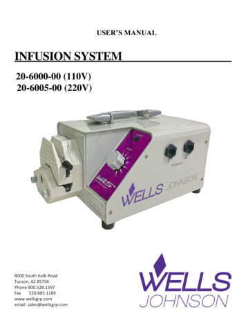
3.5 Pressure sensor testTesting tools: Infusion bottles Tube Precision pressure gauge: has been calibratedTesting steps are as follows:1.As shown in the following figure, connect the infusion pump, infusion tube and theprecision pressure gauge.Precisionpressure gauge2.Before the transfusion, the pressure gauge should read zero. If it is not zero, thendisconnect the fluid connection, make it to zero and then connect.3.In the advanced settings mode, press simultaneously thekey (Clear) andkey (Settings)into the pressure calibration interface as shown in the following figure.4.Presskey (Start) to start infusion, verify that the maximum error between anypoints within the measurement range of the pressure sensor and the pressure gauge is notexceeding 30Kpa.17
5.Use infusion pumps to inject fluids into the pressure gauge until its internal pressurereaches to 60kPa, repeat step 4.6.Use infusion pumps to inject fluids into the pressure gauge until its internal pressurereaches to 100kPa, repeat step 4.7.Use infusion pumps to inject fluids into the pressure gauge until its internal pressurereaches to 140kPa, repeat step 4.If any pressure calibration error exceeds 30Kpa, please contact our technical support staff.3.6 Battery performance testBattery function may deteriorate as it is used, it is recommended to charge and discharge thebattery every 3 months, and implement regular battery checks.Please follow the steps below when checking the battery:1.Connect the pump to the AC power, charging continuously for 8 to 14 hours.2.Disconnect the AC power supply and let the machine operate with an infusion rate of25ml/h on battery power until it switches off due to the battery being exhausted.3. If the battery works for over 200 minutes, the battery is in good condition. If the battery works for 60 to 200 minutes, the battery is close to the end of its life. If the battery works for less than 60 minutes, the battery has reached the end of itslife and needs to be replaced.Please charge the battery for future usage after performing this check.NOTE If the battery only provides power for a short time after being fully charged, itmay be damaged or faulty. The battery’s power supply time depends on theusage frequency of the pump and its setting parameters. For example: extendeduse of the display backlight. If the battery has obvious damage (e.g. misshapen, dented, leaking) or cannothold charge, it should be replaced and recycled.18
3.7 Electrical safety testWARNING Electrical safety test is a verified test for electrical safety of the monitoringdevices; it is designed to detect abnormal electrical hazards which, if notdiscovered, may cause injury to the patient or the operator. Commercially available testing devices such as the safety analyzer may be usedfor electrical safety tests. Please ask the maintenance personnel to ensure theapplicability, functional integrity and safety of such devices as well as tofamiliarize themselves with the use of these devices. Electrical safety tests shall be in accordance with the latest version of thefollowing criteria: EN 60601-1. If local regulations provide provisions otherwise, please follow the provisionswhen performing relevant electrical safety tests. In the patient area, all devices that are connected to the mains supply as well asto medical equipment must comply with the IEC 60601-1 standards, and mustbe tested for electrical safety in accordance with the test interval for monitoringdevices.Electrical safety tests are used to detect hazards that may pose electrical safety threats to thepatients, operators and maintenance personnel. Please perform electrical safety tests in anormal environment (including temperature, humidity and atmospheric pressure).While the 601 safety analyzer is used as an example in the electrical safety test described inthis chapter, different safety analyzers may be used in different regions. Please ensure theapplicability of the electrical safety test you would like to conduct.19
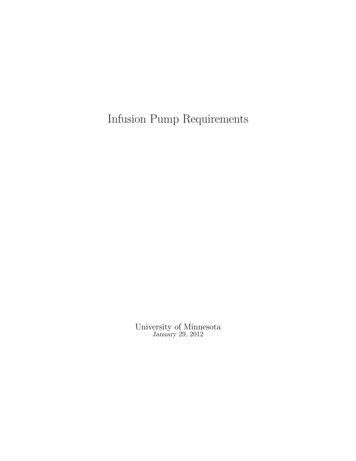
Device connection diagram is as follows:Testing tools: Safety analyzer Isolation transformer3.7.1 Housing leakage current test1.Connect the 601 safety analyzer to a power supply of 264VAC and 60Hz.2.Using the connection tooling of the application section, connect the application sectionof the tested device and connect the SUM end of the connection tooling of theapplication section to the RA end of the safety analyzer.3.Connect the tested device, via a power line, to the auxiliary power output jack of the 601safety analyzer.4.Connect one end of the red test lead to the "Red input terminal" of the safety analyzerand clip the other end to the metal foil attached to the surface of the housing of thetested device.5.Power on the 601 safety analyzer, press "5-Enclosure leakage" on the panel of the 601safety analyzer, starting the interface for the housing leakage current test.6.Housing leakage current is less than 100μA under normal condition and less than 300μAunder single-fault condition.3.7.2 Patient leakage current test1.Connect the 601 safety analyzer to a power supply of 264VAC and 60Hz.20
2.Using the connection tooling of the application section, connect the application sectionof the tested device and connect the SUM end of the connection tooling of theapplication section to the RA end of the safety analyzer.3.Connect the tested device, via a power line, to the auxiliary power output jack of the 601safety analyzer.4.Power on the 601 safety analyzer, press "Patient leakage" on the panel of the 601 safetyanalyzer.5.Continuously press the "APPLIED PART" key to select AC and DC measurements;"DC" is shown following the limit value of direct current.6.Patient leakage current is less than 10μA under normal condition and less than 50μAunder single-fault condition.If the electrical safety test fails, please contact our technical support team.3.8 Cleaning and DisinfectionThe pump must be cleaned or disinfected using the materials and methods listed in this chapter.Otherwise, our company will not be responsible for any damage or accident caused by cleaningand disinfection using other materials and methods.The manufacturer shall not be held responsible for the efficacy of the following chemicals ormethods for infection control. Please contact your hospital's infection prevention departmentor epidemiology specialists for advice on infection control practices.Please keep the infusion pump and accessories free of dust, and comply with the followingprovisions to prevent damage to the pump: Dilute all cleaning agents and disinfectants in accordance with the manufacturer’sinstructions, or use as low a concentration as possible. Do not submerge the pump in liquid. Do not pour liquid onto the device or its accessories. Avoid liquid entering the pump body. Do not use abrasive materials (such as steel wool or silver polishing agent) or anystrong xylene or acetone-type solvent, in order to prevent damage to the outer casing.WARNING21
Turn off the power and disconnect the AC power supply before cleaning theinfusion pump.The infusion pump should be cleaned regularly. The cleaning frequency should be increased inareas with serious environmental pollution or in very windy or sandy areas. Before cleaning,consult or refer to the hospital's specific regulations concerning medical device cleaning.The recommended cleaning agents and disinfectants are: Warm water Dilute soapy water Dilute aqua ammonia Sodium hypochlorite (bleaching powder for washing) Hydrogen peroxide (3%) Ethanol (70%) Isopropanol (70%)Recommended procedure for cleaning and disinfection:1.Turn off the power and disconnect the power cord.2.Use a piece of soft cloth dampened with warm water to wipe the surface of the infusionpump if any liquid is spilled on it.3.Wipe the surface of the pump with a soft cloth soaked in 75% ethanol.4.Keep the pump in a cool and ventilated environment to dry.The above steps are for reference only. The effects of disinfection should be checkedaccording to the relevant method.CAUTION Do not use ethylene oxide (EtO) gas or formaldehyde for disinfection.22
Chapter 4 Common failures and Troubleshooting4.1 OverviewIn this chapter faults of infusion pump are classified according to the components and faultyphenomena. Please refer to the relevant Fault Table when troubleshoot and examine, identifyand troubleshoot the fault in sequence.The recommended solutions should help you solve most of the equipment faults you willencounter but not all possible problems. In the case of a fault not covered in this chapter,please contact our after-sale service department.4.2 Components replacementYou may replace the circuit board components and other major c
The infusion tube must be installed straight and level in the bottom of the groove on the infusion pump. 1.1.2 WARNING WARNING Only authorized professional maintenance technicians can disassemble the Infusion pump; Pump maintenance and upgrades must be carried out by maintenance technicians trained and licensed by the manufacturer.