Transcription
USER’S MANUALINFUSION SYSTEM20-6000-00 (110V)20-6005-00 (220V)8000 South Kolb RoadTucson, AZ 85756Phone 800.528.1597Fax520.885.1189www.wellsgrp.comemail: sales@wellsgrp.com
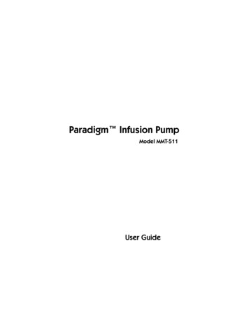
GENERAL DESCRIPTIONThe infusion pump unit incorporates an enclosed, brushless DC (BLDC) motor that has a long workinglife and permanent lubrication. The gearbox was removed for increased efficiency and extremely quietoperation. It requires no maintenance for the lifetime of the motor. The motor driver takes advantage ofa high performance DSP processor designed for 3-phase sine-wave brushless DC motor speedregulation. Power ON/OFF is achieved using the switch located on the back of the unit, and the motorspeed adjustment is accomplished with a single-turn potentiometer switch located on the front panel.SPECIFICATIONSItem numberWeightDimensionsPowerDriveMotorMaximum VacuumMaximum Head PressureContinuousIntermittentPeristaltic PumpMaximum Flow Rate20-6000-00 (110V)20-6005-00 (220V)11 lbs.7.25" x 12.5" x 6.25"100 to 240 VAC, 50/60 Hzsingle direction0 to 1050 rpm /- 100 (load dependent)24" HG25 psi40 psi @ max speed and outlet occlusion1300 ml/min. (with specified tubing)CHECKLISTThe infusion pump system consists of the following ten (10) basic components:·Pump Controller (unit)·Pump Head·Power Cord·Pneumatic Foot Switch·Infusion Tubing (5 pieces)·Black Aluminum Handles (2)·Infusion Cannulas (2)·Spinal Needles (3)·IV Bag Stand·User’s ManualItems being returned must be carefully packed to prevent damage in shipment, and insuredagainst possible damage or loss. Wells Johnson Company will not be responsible for damageresulting from careless or insufficient packing.*NOTE: Products with an expired warranty will be repaired for a nominal charge.*
COMPONENT DESCRIPTIONPUMP HEADLOADINGSterile solution may be pumped through Infusion Tubing using the following technique to load thepump head:1.2.3.4.Spike BagClamp TubingRotate the pump head lever counter clockwise to open the pump head.Insert the enlarged center section of the infusion tubing into the pump head opening over therollers. The flow direction should be from left to right as notes on the pump head.5. Rotate the pump head lever clockwise to close the pump head and clamp the tubing.PNEUMATIC FOOT SWITCHThe foot switch tubing is connected to either port located on the side of the pump.INFUSION TUBINGUse sterile Infusion Tubing only. Manufacturer suggest only using approved Wells Johnson tubingplease refer to parts list. This tubing is precision-extruded and optically inspected to insure topperformance with the pump head. Other commercial tubing may not meet, or perform, tospecifications.Warning: Infusion tubing sterile, single-use and not intended to be reused under anycircumstances to prevent cross-contamination.*NOTE: Refer to the section on the pump head for installation.*BLACK ALUMINUM HANDLESBlack Aluminum Handles are designed to accept infusion tubing via luer lock connection. Standardluer lock needles or infusion cannulas are connected to the handle via conventional luer lock. TheBlack Aluminum Handle may be gassed, autoclaved, or soaked.INFUSION NEEDLESThe infusion technique is based on using large volumes of a very dilute concentration of localanesthetic, which produces extremely efficient anesthesia, while minimizing blood loss.All infiltration needles (or cannulas) are manufactured from surgical grade stainless steel with luerlock fittings (specify length and diameter when ordering).IV BAG STANDPlace the IV Stand into the bracket located on back of pump. The stand is uni-directional and will gointo place when hooks are centered over the pump.*Caution: Make sure stand is inserted all the way into bracket (1-3/4") before attaching solutionbags.*
SET UP AND OPERATIONThe variable speed drive provides ease of operation. Place pump on stable surface. After installingthe tubing in the pump head (refer to the “Pump Head” section), connect the power cord to anacceptable power outlet. Adjust the speed control knob to the desired speed. The foot switchmust be activated for pump to operate.NOTE: The numbers under the speed control knob are for reference only. If the direction of flowneeds to be changed, reverse the intake and discharge sides of the tubing.The pump control unit and the pump head remain outside of the sterile operating field. The peristaltictype pump head assures the sterile fluids remain within the tubing, never allowing direct contact witheither the pump head or the pump control unit.*Caution: To prevent air infusion, always prime tubing prior to administering any fluid topatient.*PARTS LIST:ItemInfusion Pump (110V)Part #20-6000-00Infusion Pump (220V)20-6005-00Power Cord (110v)18-2820-00Power Cord (220v)20-5101-11Infusion Pump Head, single18-4102-00Pneumatic Footswitch20-6010-01IV Bag Stand18-4200-00Multi Hole Infusion Cannulas (specify size)20-1218-003-Hole Spatula Infusion Cannulas (specify size)20-1223-00Spiral Infusion Cannulas (specify size)20-1243-00Multi Hole 12 Infusion Cannulas (specify size)20-1252-00Open Ended Infusion Cannulas (specify size)20-1257-00Black Aluminum Infusion Handle16-5181-00Spinal Needles; sterile, disposable18g x 6” (1 ea.)24-6002-0025g x 3” (1 ea.)24-6003-0020g x 3.5” (1 ea.)24-6004-00CB Infiltration Tubing; sterile, disposable, single-use, single spike24-6008-00“Y” Infiltration Tubing; sterile, disposable, single-use, dual spike24-6009-00Large Bore Infiltration Tubing; sterile, disposable, single-use, single spike24-6028-00“YLB” Infiltration Tubing; sterile, disposable, single-use, dual spike24-6029-00
TROUBLE SHOOTINGThe two black buttons under the lever can be pushed inward allowing it to slide up or down to adjustthe tubing size.Sliding button upward loosens pump head grip on the infusion tubing. Tubing will have a tendency to“walk”, or bunch-up, in the pump head if the buttons are adjusted too high.Adjusting the button downward tightens the pump head grip on the tubing. Adjusting the buttons too fartoward the bottom of their excursions may restrict the flow rate.NOTE: Adjustment of the buttons 3 ‘clicks’ from the top of their excursion provides an optimumsetting between flow and grip.MAINTENANCEMaintenance-Free unit.Do not submerge.Clean with hospital grade cleaning agent.TECHNICAL ASSISTANCETechnical assistance may be obtained by contacting the Wells Johnson Company Customer ServiceDepartment at 800-528-1597 or local 520-298-6069The Wells Johnson Company reserves the right to make improvements in design, construction, andappearance of our products without notice.Caution: Federal law restricts this device to sale by or on the order of a physician.
WARRANTYThe Wells Johnson Company will void warranty on anyproducts indicating negligence, or noncompliance withoperation maintenance instructions.Products are warranted against defect in material andworkmanship for a period of five (5) years from date ofpurchase. If repair or adjustment is necessary, and are notthe result of abuse or misuse, please return, freightprepaid, and correction will be performed without charge.All returns require prior authorization from the WellsJohnson Quality Assurance Department.For technical assistance callCustomer Service or Technical Support:520-298-6069800-528-1597Rev: 080519SECN 574
Phone 800.528.1597 Fax 520.885.1189 www.wellsgrp.com email: sales@wellsgrp.com . . Infusion Pump Head, single 18-4102-00 Pneumatic Footswitch 20-6010-01 IV Bag Stand 18-4200-00 Multi Hole Infusion Cannulas (specify size) 20-1218-00 3-Hole Spatula Infusion Cannulas (specify size) 20-1223-00 .