Transcription
Razor X PropellerInstallation and Operation Instructions1 of 9
IntroductionRazor X PropellersX-Core CompositeTM TechnologyWhirlWind Razor X Propellers offerexcellent performance and unsurpasseddurability. Every blade is equipped witha strong carbon spar for strength, has anelectro-formed Nickel leading edge shieldfor abrasion protection, and is constructedusing our new X-Core CompositeTMtechnology.Unlike most airboat propellers on themarket, Razor X blades are constructed witha structural solid foam core and carboncomposite skins to create an incrediblystrong, stiff and lightweight blade.Benefits of X-Core CompositeTM :llStructural foam core providesunequaled strength and durability.llEntire outer skin is stabilized by theYou will find Razor X propellers easyto assemble and make blade pitchadjustments. Follow the attachedinstallation and maintenance instructionsfor years of trouble free operation.foam core, eliminating vibrations andflexing during operation.llInstant push on start up as the bladesdo not flex or bend.llResonance issues from the engine andRequired Toolsgear box noise are greatly reduced.llBlades have a high damage tolerance dueYou will need the following tools toassemble your propeller:to the foam core, making them easier torepair than standard hollow blades.a. 3/4” ratchet and socketSafety Informationb. 5/16” ratchet and socketc. Torque WrenchWARNING: Read and follow all instructionsccbefore operating the propeller!d. Digital Levela.c.b.d.WARNING: Use extreme cautionccanytime you are near the propellerwhether the propeller is turning or not, assevere bodily harm or death may result.WARNING: Keep hands, feet, andccbody away from the propeller at all0.0times. Failure to do so will result insevere bodily harm or death.NOTE: WD-40 is recommendedbbto clean the prop flange beforeinstallation and anti-seize compoundshould be used on all hardware.WARNING: Never allow anyone to standccin the same plane as the propeller.2 of 9
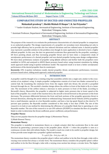
Installation1/2” MOUNTING BOLTS (x6)A Prepare Outer Plate5/16” BLADECLAMPINGBOLTSa. Insert all six 1/2” Mounting Boltswith Washers through the six holesin the center of the Outer Plate.b. Insert 5/16” Blade Clamping Bolts(4 per blade) with Washers throughthe Outer Plate where shown.c. Slide Blade Blocks over each set of5/16” Blade Clamping Bolts.BLADE BLOCKSOUTER PLATEBLADESB Install Bladesa. Set the Excalibur blades into theBlade Blocks.BLADE BLOCKb. Slide Blade Blocks over each setof 5/16” Blade Clamping Bolts andensure each blade is seated securelybetween the Blade Blocks.c. Set six Spacers over the 1/2”Mounting Bolts.SPACER (x6)C Install Engine-Side Platea. Slide the Engine-Side Plate over theMounting and Blade Clamping Bolts.ENGINE-SIDE PLATE5/16” WASHERSAND NUTSb. Re-check the Blade Blocks andensure each blade is still seatedproperly.c. Install the 5/16” Washers and Nutson each Blade Clamping Bolt andhand tighten. Do not torque tospecifications yet.NOTE: Do NOT force or hammerbbany propeller parts together.3 of 9
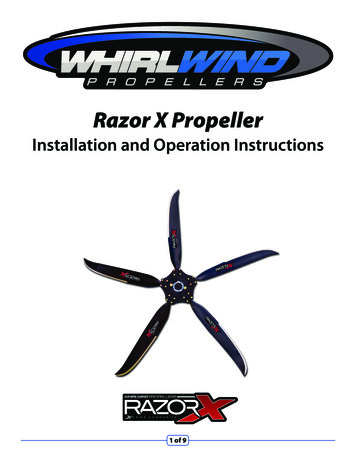
InstallationD Install the Propeller on the Airboatb. To set the initial pitch, rotate thepropeller so the blade is horizontal.Place a digital level flat on the blade, 2”to 3” from the tip.a. Make sure your prop-shaft is cleanand free of rust and corrosion. Thiscannot be stressed enough. A cleanand rust free flange will ensure properinstallation and will prevent the hubfrom permanently bonding to yourflange with rust.NOTE: It is recommended to spray yourbbflange with a rust inhibitor (such as LPSor WD40) prior to propeller installation.c. For the initial pitch setting, start with apitch (or blade angle) of about 10 fromthe vertical axis. Remember that thegreater the pitch, the lower RPM theengine will run. A lesser pitch will allowthe engine to run at higher RPM’s.BLADE ROTATIONIN HUBb. Mate the propeller to the prop-shaftand install the six 1/2” Mounting Boltsand Washers. Tighten the bolts using ahexagonal star pattern as shown below.Make sure the propeller is securely pulledup onto the prop-shaft - no gaps allowed.14523610 BLADEANGLEc. Torque 1/2” Mounting Bolts to40 ft-lbs.VERTICALAXISd. Torque the 5/16” Blade Clamping Boltsto 16 ft-lbs. before operating propeller.FINAL CHECK:E Initial Pitch SettingAny blade movement in the hub isunacceptable. Ensure the hub has beeninstalled flat against mounting flange,and that each blade is well seated in thehub (not misaligned or crooked).a. Loosen the 5/16” Blade Clamping Boltsuntil the blade can be easily rotatedby hand.4 of 9
InstallationF Initial Engine RunNOTE: Before starting your enginebband new propeller for the first time,ensure the propeller blades clear allengine parts (suggested minimumclearance of at least 2”). Repeat thisstep each time you change the pitchsetting of your propeller.After the propeller is installed, referto the following table for maximumrecommended RPM to avoid damageduring operation.MAXIMUM PROPELLER RPMa. Run the engine up to 2000 propellerRPM. Shut the engine down.Max. RPM Range Starting BladeRPMAngle @Tip68” to 74” 3000 2500 to 300010 76” to 80” 2700 2200 to 270010 82” to 84” 2500 2000 to 250010 Diameterb. Inspect the overall condition ofthe blades, leading edge and hub.Firmly grab each blade tip and applya forward and aft force to ensureeach blade is tight in the hub. Do notoperate the propeller if the bladeshave any movement in the hub.WARNING: DO NOT EXCEED MAXccPROPELLER RPM! Propeller bladefailure may occur if max. propellerRPM is exceeded - resulting in severebodily injury or death!c. Check for proper torque on all bolts(5/16’’ bolts to 16 ft-lbs and 1/2’’ boltsto 40 ft-lbs).WARNING: Ignition Timing not toccexceed 25 degrees, top dead center,on aircraft engines.WARNING: Harmonic Damper isccrequired on the following engines.Warranty void if installed otherwise.ll8 Cylinder Continental GPU enginesllDirect Drive Cadillac Auto Engines5 of 9
InstallationG Maximum RPM Settingc. Check the bolt torque and performvisual inspection as described in“Propeller Care and Maintenance” afterevery 20 to 25 hours of operation.Enjoy your new propeller and have fun!a. After you have completed the InitialEngine Run in Step 6, you can nowperform a full Max. engine RPM (fullthrottle) run while the boat is safelysecured, but DO NOT EXCEED MAX.PROPELLER RPM! (See Step 6)Performance Tip: Static Max. RPMbbb. Adjust the pitch (blade angle) until targetMax. engine RPM (full throttle) is achieved.llIf the engine RPM is too low, decreasethe pitch setting to increase RPM.llIf the engine RPM is too high, increasethe pitch setting to decrease RPM.High PitchSettingLow PitchSettingBLADEBLADE(full throttle) should be 200 RPM lessthan the target Wide Open Throttle(WOT) RPM. Engine will increase200 RPM when the boat is traveling attop speed.Performance Tip: Lower Cruise RPMbband better Fuel Economy can beachieved with a lower Max. RPM (fullthrottle) and higher pitch setting (bladeangle). You may not want or need toturn your engine to its maximum RPMif you are interested in reducing noiseor increasing fuel economy.Tech Tip: If vibration is detected duringbbpropeller operation, do the following:llFirst check the blade pitch setting8 BLADEANGLEVERTICALAXIS12 BLADEANGLEVERTICALAXISWARNING: Never use a malletccor other object to tap the bladeduring pitch setting.6 of 9on each blade and ensure they arewithin 0.5 deg of each other.llNext ensure the hub is properlyseated on the propeller flange(no gaps).llFinally, check the blade track- eachblade should track within 1/8” atthe tip.
Propeller Care and MaintenanceProper care and maintenance of your WhirlWind propeller will ensure a long life withmany hours of trouble free operation.HubllWash & clean the hub with a milddetergent (such as Simple Green).llInspect the overall condition of theA complete inspection of your propellershould be performed periodically, at leastafter every 25 hours of operation. Beforeeach use, carefully examine the propellerblades and hub for looseness, any signsof damage, excessive wear or any othercondition that would make the propellerunsafe to operate.hub. Inspect the interior and exteriorthoroughly for any signs of hair-linecracking. If any cracks are detected,contact Whirl Wind for assessment.BoltsCheck the bolt torque on all bolts.ll5/16” bolts to 16 ft-lbsll1/2” bolts to 40 ft-lbsIn particular, before operating check: hubbolt torque, propeller hub for any signsof cracking, blade shanks for roughness orraised fibers, blades for impact damage orcracks, and the metal erosion shieldfor tightness.NOTE: Every Razor X blade isbbmanufactured using a state-of-theart production process that yields asmooth surface finish on each blade.BladesAny slight marks on the surface ofthe blades, such as small bubblesand/or pinholes, are common to thisproduction process and do not affectthe structural integrity of the blade.llWash & Clean all blades with a milddetergent (such as Simple Green).llOptional: Polish blades with clear liquidautomotive polish for an additionallayer of UV protection (such as TurtleWax Ice).llInspect the overall condition of blades,looking for chips, cracks, and anyleading edge damage. If the leadingedge is damaged, this can be repairedby returning to Whirl Wind with the fullset of blades. If damage is neglected, itmay worsen, making repair impossible.7 of 9
30 Day Satisfaction GuaranteeWhirl Wind Propellers Corporation guarantees your satisfaction for a period of 30 days fromdate of purchase to the Original Purchaser. If during this time you are not satisfied with ourproduct you may send the propeller back for an exchange or for a full or partial refund. Anyshipping and handling charges are non-refundable. If you have tested the propeller on yourboat, the propeller may be subject to a restocking fee if the propeller shows excessive signsof wear or abuse.Simply return the propeller to the address below. Returned items must be within 30 days ofpurchase to qualify. Return shipping must be prepaid and insured for the full value of thepropeller or parts. The cost of returning the propeller is incurred by the customer. Whirl WindPropellers reserves the right to refuse any return found to be the result of a suspicious originor untrustworthy nature.Return Address:Whirl Wind Propellers1800 Joe Crosson Drive, Ste CEl Cajon, CA 92020Whirl Wind Propellers CorporationWhirl Wind Propellers1800 Joe Crosson Drive, Ste CEl Cajon, CA 92020(619) 562-3725www.whirlwindpropellers.com8 of 9
Limited WarrantyWhirl Wind Propellers Corporation expressly warrants its products to be free from defects in material and workmanshipunder normal use and service for a period of twelve (12) months after delivery to the original retail purchaser.WARNING: Whirl Wind airboat propellers are not suitable for installation on the following engines without theccuse of a harmonic damper. Installation on these engines shall void all warranty claims.ll8 Cyl Continental GPU EnginesllDirect Drive Cadillac Auto EnginesWARNING: Whirl Wind airboat propellers are not suitable for installation on the aircraft engines that haveccremoved the crankshaft counterweights. Installation on these engines shall void all warranty claims.WARNING: Whirl Wind airboat propellers are not covered by warranty when used for racing of any kind due to theccinfinite variety of racing modifications and set-ups. The racer assumes all risks and accepts personal responsibilityfor any and all loss, liability, damages, or costs following such injury, permanent disability, or death.WARNING: Any Blade Style with a diameter of 76” or greater may ONLY be installed on engine applicationsccusing reduction systems. Direct drive installations are not permitted and are not safe to operate. Direct Driveinstallations of these blade styles shall void all warranty claims.WARNING: For Aircraft engine installations, timing advance must not be greater than 25 degrees Top DeadccCenter or warranty shall be void.Whirl Wind Propellers Corporation’s obligation under this limited warranty is limited to repairing or replacing, atits option, any propeller or propeller hub, determined by Whirl Wind to have been defective and which is properlyreturned by the owner, with a written statement describing the alleged defect, to its place of business at El Cajon,California USA. Any replacement of a unit or a part of a unit during the warranty period will not extend the warrantybeyond the original duration.Procedure For Obtaining Warranty Service: All warranty returns are to be shipped prepaid and insured for thefull value of the item being returned to Whirl Wind Propellers Corporation at the address listed below. Upon receipt ofthe unit, Whirl Wind Propellers Corporation will decide which remedy, repair, or replacement it will provide. The unitmust be accompanied by a copy of the original (Distributor or Dealer) invoice and a brief description of the defect. Theremedy of repair or replacement is exclusive and does not include the cost of shipping, removal, or installation, all ofwhich are the customer’s responsibility.Whirl Wind Propellers – Warranty Returns1800 Joe Crosson Drive, Ste CEl Cajon, CA 92020Conditions, Exclusions, and Disclaimers: This limited warranty applies to units that have been used andmaintained properly. It does not cover units that show abuse, alterations, improper installation, or improper packagingfor shipment; and it does not pertain to damage due to object strike or excessive blade wear due to operation.To the extent allowed by applicable law, THIS WARRANTY IS EXPRESSLY IN LIEU OF ANY OTHER WARRANTIES,EXPRESSED OR IMPLIED IN FACT OR BY LAW, INCLUDING ANY IMPLIED WARRANTY OF MERCHANTABILITY OR FITNESSFOR A PARTICULAR PURPOSE. THE REMEDIES OF REPAIR OR REPLACEMENT SET FORTH HEREIN ARE THE ONLYREMEDIES UNDER THIS WARRANTY. Whirl Wind DISCLAIMS ANY OBLIGATION OR LIABILITY, WHETHER IN CONTRACT ORIN TORT, INCLUDING LOSS OF USE OF THE PRODUCT WARRANTED, LOSS OF TIME, INCONVENIENCE, LOSS OF PROFITS,COMMERCIAL LOSS OR ANY OTHER
leading edge damage. If the leading edge is damaged, this can be repaired by returning to Whirl Wind with the full set of blades. If damage is neglected, it may worsen, making repair impossible. Propeller Care and Maintenance Hub lbWash & clean the hub with a mild detergent (such as Simple Green). lbInspect the overall condition of the hub. Inspect the interior and exterior