Transcription
SANDIA REPORTSAND2014-0681Unlimited ReleasePrinted January 2014SMART Wind Turbine Rotor:Design and Field TestJonathan C. Berg, Brian R. Resor, Joshua A. Paquette, and Jonathan R. WhitePrepared bySandia National LaboratoriesAlbuquerque, New Mexico 87185 and Livermore, California 94550Sandia National Laboratories is a multi-program laboratory managed and operated by Sandia Corporation,a wholly owned subsidiary of Lockheed Martin Corporation, for the U.S. Department of Energy'sNational Nuclear Security Administration under contract DE -AC04-94AL85000.Approved for public release; further dissemination unlimited.
Issued by Sandia National Laboratories, operated for the United States Department of Energyby Sandia Corporation.NOTICE: This report was prepared as an account of work sponsored by an agency of theUnited States Government. Neither the United States Government, nor any agency thereof,nor any of their employees, nor any of their contractors, subcontractors, or their employees,make any warranty, express or implied, or assume any legal liability or responsibility for theaccuracy, completeness, or usefulness of any information, apparatus, product, or processdisclosed, or represent that its use would not infringe privately owned rights. Reference hereinto any specific commercial product, process, or service by trade name, trademark,manufacturer, or otherwise, does not necessarily constitute or imply its endorsement,recommendation, or favoring by the United States Government, any agency thereof, or any oftheir contractors or subcontractors. The views and opinions expressed herein do notnecessarily state or reflect those of the United States Government, any agency thereof, or anyof their contractors.Printed in the United States of America. This report has been reproduced directly from the bestavailable copy.Available to DOE and DOE contractors fromU.S. Department of EnergyOffice of Scientific and Technical InformationP.O. Box 62Oak Ridge, TN 37831Telephone:Facsimile:E-Mail:Online ordering:(865) 576-8401(865) /bridgeAvailable to the public fromU.S. Department of CommerceNational Technical Information Service5285 Port Royal Rd.Springfield, VA 22161Telephone:Facsimile:E-Mail:Online order:(800) 553-6847(703) v/help/ordermethods.asp?loc 7-4-0#online2
SAND2014-0681Unlimited ReleasePrinted January 2014SMART Wind Turbine Rotor:Design and Field TestJonathan C. Berg, Brian R. Resor, Joshua A. Paquette, and Jonathan R. WhiteWind Energy Technologies DepartmentSandia National LaboratoriesP.O. Box 5800Albuquerque, New Mexico 87185-MS1124AbstractThe Wind Energy Technologies department at Sandia National Laboratories hasdeveloped and field tested a wind turbine rotor with integrated trailing-edge flapsdesigned for active control of rotor aerodynamics. The SMART Rotor project wasfunded by the Wind and Water Power Technologies Office of the U.S. Department ofEnergy (DOE) and was conducted to demonstrate active rotor control and evaluatesimulation tools available for active control research. This report documents thedesign, fabrication, and testing of the SMART Rotor.This report begins with an overview of active control research at Sandia and theobjectives of this project. The SMART blade, based on the DOE / SNL 9-meterCX-100 blade design, is then documented including all modifications necessary tointegrate the trailing edge flaps, sensors incorporated into the system, and thefabrication processes that were utilized. Finally the test site and test campaign aredescribed.3
ACKNOWLEDGMENTSThe SMART rotor project was funded by the U.S. Department of Energy (DOE) Wind andWater Power Technologies Office (director Jose Zayas) under the office of Energy Efficiencyand Renewable Energy (EERE, assistant secretary David Danielson).The authors gratefully acknowledge all those who contributed to this project, including thefollowing:USDA-ARS staff at Bushland Test Site Adam Holman Byron NealTesting Wesley Johnson Bruce LeBlanc Nate Yoder (ATA Engineering)Data Acquisition System programming Juan Ortiz-Moyet (Prime Core)Blade Modification David Calkins Mike Kelly Bill MillerBlade Manufacture by TPI CompositesSMART blade design Matt Barone Dale Berg Jonathan Berg Gary Fischer Josh Paquette Brian Resor Mark Rumsey Jon WhiteConsultation Derek Berry (TPI Composites) Mike Zuteck (MDZ Consulting)4
CONTENTS1. Introduction . 111.1. Background of SMART Rotor Research at Sandia . 121.2. Project Objectives . 122. Blade Design . 132.1. Options Considered . 132.2. Conceptual Design . 142.3. Structural Design . 152.3.1. Initial Detailed Design of Structural Changes . 152.3.2. Sectional Analysis of Initial Design with PreComp . 172.3.3. Final Structural Design . 192.3.4. Finite Element Analysis (FEA) of Final Design . 202.4. Maximum Aerodynamic Forces and Moments. 282.5. Hinged Flap Module Design . 302.5.1. Module Components . 302.5.2. Required Actuator Torque . 332.5.3. Actuator Selection . 352.5.4. Module Stress Analysis . 373. Blade Construction and Device Integration . 393.1. Instrumentation Plan . 393.2. Mitigation of Electrostatic Discharge . 393.3. Blade Construction. 403.4. Post-build Blade Modification . 413.5. Flap Module Construction and Integration . 434. Control Hardware. 455. Field Test . 475.1. Layout of the Test Site . 475.2. Test Turbine . 485.3. Instrumentation . 495.4. Test Cases . 496. Conclusion . 537. References . 55Appendix A: Original CX Layup . 59Low Pressure Skin . 59High Pressure Skin . 62Appendix B: Changes to PreComp v1.00.02 . 64Appendix C: VectorPly Data Sheet . 65Appendix D: PreComp Section Analysis Inputs . 67Material Properties . 67Input file . 67Webs: . 675
Main shear web . 67Aft flange . 67Station 5 . 68Overall 68Layup (webs present but not shown here) . 68Station 5.1 (cutout). 69Overall 69Layup (webs present but not shown here) . 69Station 6.1 (cutout). 72Overall 72Layup (webs present but not shown here) . 72Station 7.1 (cutout). 75Overall 75Layup (web present but not shown here) . 75Station 8.1 . 78Overall 78Layup (web present but not shown here) . 78Appendix E: SMART Blade Layup . 79Low Pressure . 79High pressure . 80Appendix F: Inflow and Turbine Instrumentation . 82Appendix G: Data File Summaries . 84Distribution . 926
FIGURESFigure 2.1Figure 2.2Figure 2.3Figure 2.4Figure 2.5Figure 2.6Figure 2.7Figure 2.8Figure 2.9Figure 2.10Figure 2.11Figure 2.12Figure 2.13Figure 2.14Figure 2.15Figure 2.16Figure 2.17Figure 2.18Figure 2.19Figure 2.20Figure 2.21Figure 2.22Figure 2.23Figure 2.24Figure 3.1Figure 3.2Figure 3.3Figure 3.4Figure 4.1Figure 5.1Figure 5.2Figure 5.3Figure 5.4Interchangeable tip of a DG800 Sailplane. .14Blade retrofit concept. .15Flap module AAD concept. .15CX-100 layup and SMART blade alterations. .16Outboard blade planform. .17Sectional analysis results of original CX-100 and SMART blade. .19SMART Blade FEA Model. .20Trailing edge cutout modification to model. .21Outboard section of model. .21Outboard webs and rib. .21Model with loads applied. .22Loading applied at outboard section. .22HP spanwise strains. .23LP spanwise strains. .24Main web shear strains. .25Aft web shear strains. .26Rib shear strains. .27Flap AAD module design overview. .30Module base design. .31Additional features in second module. .32Module flap design. .32Final flap module design. .33Simulated angle-of-attack along blade span. .34Motor torque-speed curves. .36Schematic of internal sensor locations. .40Blade set after removal of trailing edge. .41Aft spar bonded into place. .42Fully assembled SMART blade set. .43AAD control box. .46Schematic overview of the test site. .47Site plan with detailed dimensions. .48Strain response to flap step sequence. .50Sequence of video frames during turbine operation. .517
TABLESTable 2.1Table 2.2Table 2.3Table 2.4Table 2.5Table 2.6Table 2.7Table F.1Table F.2Table F.3Table G.1Table G.2Table G.3Table G.4Table G.5Table G.6Table G.7Table G.8Table of trailing edge changes in PreComp analysis. .18Layer thickness for laminate materials. .19Force and moment coefficients at flap hinge line. .29Force and moment coefficients at module-to-blade interface. .29Calculated forces and moments on each module. .29Mass properties of the flaps. .33Flap inertial loading due to blade flapwise motion. .35Inflow Instrumentation. .82Turbine Instrumentation. .82Rotor Instrumentation. .83Initial shakedown. .84First operation during power production. .85Static flap settings with 10-minute data files. .86Sine sweeps during power production. .87Power production at prevailing wind direction with flap step series. .88Power production with flap step series. .89Data files during video of flaps in operation. .90Power production with tape sealing possible air gaps in flap modules. .908
NOMENCLATUREAADactive aerodynamic deviceAALCactive aerodynamic load controlafttoward the trailing edge of a wind turbine bladechordwisein the direction of airfoil chord and perpendicular to blade spanDOEDepartment of Energy (U.S.)edgewisesimilar to chordwise but used to describe blade loads and deflectionsESDelectrostatic dischargeflapwiseperpendicular to edgewise and in the direction of blade “flapping” motionHAWThorizontal axis wind turbineHPhigh-pressure (the nominally upwind surface of a HAWT blade)inboardtoward the root end of a wind turbine bladelayupthe stack of layers which constitute a composite blade structureLPlow-pressure (the nominally downwind surface of a HAWT blade)outboardtoward the tip of a wind turbine ape of a blade as viewed from the HP or LP sideR&Dresearch and developmentSMARTStructural and Mechanical Adaptive Rotor TechnologySNLSandia National Laboratoriesspanwisein the direction of the blade lengthUVultra-violet light9
10
1. INTRODUCTIONAs the United States seeks to establish a diverse portfolio of clean and renewable energysystems, continued development of wind energy technology is essential to reaching renewableenergy deployment goals. The Report on the First Quadrennial Technology Review (QTR),published by the U.S. Department of Energy in September 2011, was written to “establish aframework for thinking clearly about a necessary transformation of the Nation’s energy system”[1]. The QTR was a first step in developing guiding principles for DOE to prioritize investmentof R&D funds. Within the “Clean Electricity Generation” strategy outlined in the report, windenergy is described as a fairly mature technology which is cost competitive at good wind sitesand continues to expand market deployment. At a high-level assessment, the report states thetechnical headroom for additional research and development exists mainly in grid integration andsubsystem reliability as well as tapping into the offshore wind resource.The 20% Wind Energy by 2030 report [2], published in July 2008, provides a more detailedassessment of the technical headroom for additional R&D. The core opportunities it identifiesinclude reducing capital costs, increasing capacity factors, and mitigating risk through enhancedsystem reliability. The rotor itself is highlighted as a key target for technology improvementbecause it is the source of all energy captured and of most of the structural loads entering thesystem. Increasing rotor size while controlling rotor loads will directly impact the capacity factorand the life of components within the main load path. The report mentions both passive loadcontrol in which the structural and material properties of the blades are tailored to passivelymitigate loads and active load control in which a control system senses rotor loads and activelyresponds by driving aerodynamic actuators.Reducing ultimate and oscillating (or fatigue) loads on the wind turbine rotor can lead toreductions in loads on other turbine components such as the main bearings, gearbox, andgenerator. This, in turn, is expected to reduce maintenance costs and may also allow a giventurbine to use longer blades to capture more energy. In both cases, the ultimate impact is reducedcost of wind energy. With the ever increasing size of wind turbine blades and the correspondingincrease in non-uniform loads along the span of those blades, the need for more sophisticatedload control techniques has produced great interest in the use of aerodynamic control devices(with associated sensors and control systems) distributed along each blade to provide feedbackload control (often referred to in popular terms as ‘smart structures’ or ‘smart rotor control’). Areview of concepts and inventory of design options for such systems have been performed byBarlas and van Kuik at Delft University of Technology (TU Delft) [3]. Active load controlutilizing trailing edge flaps or deformable trailing edge geometries is receiving significantattention because of the direct lift control capability of such devices. Researchers at TU Delft [45], Risø/Danish Technical University Laboratory for Sustainable Energy (Risø/DTU) [6-12] andSandia National Laboratories (SNL) [13-19] have been active in this area over the past decade.11
1.1. Background of SMART Rotor Research at SandiaSandia’s involvement with active aerodynamic load control (AALC) can be traced back tocollaborations with C.P. van Dam and R. Chow on the microtab device concept [20] and also tointernal efforts of D. Berg, J. Zayas, and D. Lobitz to identify the controls, sensors, and actuatorsneeded to implement these or similar devices [21]. Since that time, work has steadily progressedto improve simulation capabilities and evaluate the potential benefits of AALC on wind turbineperformance. This work established hypothetical approaches for integrating active aerodynamicdevices (AADs) into the wind turbine structure and controllers, but it has needed the validationand additional insight that a field test would provide. In 2010, Sandia began a three-year projectto design, build, and test a rotor with integrated sensors and active aerodynamic load controldevices.1.2. Project ObjectivesWhile there were many questions associated with the use of active aerodynamic devices thatmust be answered with field testing experience and experimental data, the general goals wererestricted to the following: Test the control authority of one particular type of AAD.Acquire experimental data required to evaluate AALC simulation tools.Evaluate/demonstrate numerous aerodynamic and structural sensor systems to determinethose that offer the most benefit as signal inputs for the AALC controllers.Develop procedures for characterizing an operating wind turbine system whichincorporates AALC.Identify structural design changes required within a rotor blade to accept the AAD.Identify requirements and challenges producing an integrated AALC rotor blade.12
2. BLADE DESIGN2.1. Options ConsideredInitial project planning focused mainly on adapting the DOE/SNL CX-100 research blade as thestarting point for the SMART blade design. Choosing to retrofit the existing CX-100 bladedesign would allow the design team to focus on the AAD implementation and blade integrationand to build upon previous design work thereby minimizing the amount of analysis required toensure the new design could withstand operating loads. Much experience and knowledge hadbeen gained through testing of the CX-100 [22-24], TX-100 [22-24], and Sensor Blade [25-26].The structural properties and aerodynamic performance of the baseline CX-100 blade design hadbeen well characterized through field and lab testing. Sensor integration techniques had beendeveloped and proven with the Sensor Blade / Rotor projects. The TX-100 was not used for thisproject because the combination of passive and active load control, although promising for futureprojects, was considered unnecessarily complicating for the objectives of this project.A significant challenge of the SMART blade design was the limited space available in theoutboard portion of this 9-meter blade within which to fit AAD mechanisms. Although using aslightly larger scale blade and turbine was attractive, the benefits of having a well characterizedbaseline for comparison and not needing to duplicate previous design efforts were two factorswhich pointed strongly toward choosing the CX-100 design.With regard to the AAD technology itself, the design team considered microtabs and two typesof trailing edge flaps: conventional rigid hinged and flexible with continuous deformation.Researchers at the University of California, Davis (UC Davis) had been investigating microtabsfor a number of years using both high fidelity simulation and wind tunnel testing. Theyconducted their work both independently and under contract with Sandia. Within the last fewyears leading up to this report they tested a microtab design with actively deployable tabs in awind tunnel. At Sandia, another mechanism for deployable microtabs was prototyped. However,at the beginning of the SMART rotor project, there was much uncertainty regarding the amountof effort required to scale down these prototypes to the size required to fit within the availablespace.In previous work with FlexSys Inc., Sandia investigated deformable trailing edge technology andsketched out a plan for integration into a wind turbine blade. However, once again there wasmuch uncertainty about scaling down the technology for the SMART rotor.Thus, to minimize uncertainty and risk in the project, the design team decided to use aconventional rigid flap design which would be actuated much like a scale-model airplane’scontrol surfaces. Although a rigid flap was not as aerodynamically efficient as a deformabletrailing edge design, it satisfied the objectives of demonstrating the control authority of an activeaerodynamic device and testing the capabilities of AALC simulation tools.13
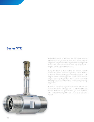
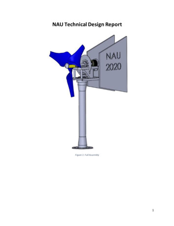
2.2. Conceptual DesignInitial thoughts on AAD integration moved toward a modular concept in which the whole bladetip would be interchangeable. Figure 2.1 shows an example of an interchangeable tip for theglass composite wing structure of a sailplane. Although this idea was attractive for the flexibilityof trying multiple active aerodynamic device technologies, the amount of design work needed toimplement the idea would have detracted from the main project goals and increased project risk.Additionally, the potential discontinuities in the structural dynamics across the joint may havecreated unnecessary complexity and substantial differences compared to the baseline CX-100structural dynamics.Figure 2.1 Interchangeable tip of a DG800 Sailplane. Photos by Brian Resor.The concept for AAD integration converged on modification to the outboard trailing edgesection while leaving the original main blade structure intact. The overall concept is portrayed inFigure 2.2 in which the original shear web (teal) is visible and the two new structuralcomponents, the aft spar (magenta) and inboard rib (orange), have been added where the trailingedge section was removed. The aft spar rejoined the upper and lower skins, thereby completingthe “torque tube” to provide a path for loads, and it also provided a mounting location for theAAD hardware. The rib was added to provide a load path between the main shear web and theaft spar.The concept also maintained a somewhat modular aspect because different AAD hardwarepackages could theoretically be designed to fit the available space. However, the feasibility ofmaking new modules would depend on compatibility of the new hardware with the placement ofmounting features and control cabling.The initial concept for the hinged flap AAD is shown in Figure 2.3. The base piece (bluetrapezoidal piece) housed the motor actuator and mounted to the aft spar. A timing belttransmitted the motor shaft motion to the flap (red triangular piece).14
(7m span)( 8m span)( 8.5m span)Figure 2.2 Blade retrofit concept with representative blade cross sections at 7m, 8m, and8.5m showing the shear web (teal C-channel), rib (orange triangle), and aft spar(magenta).Figure 2.3 Flap module AAD concept.2.3. Structural DesignAn overview schematic of the baseline CX-100 layup is shown in Figure 2.4 and detaileddrawings are contained in Appendix A. This design incorporated carbon fiber spar caps whichran nearly the entire length of the blade, providing increased stiffness. A single shear web,constructed of fiber glass and balsa, bridged between the two blade skins at the spar cap location.In the outboard trailing-edge panels aft of the spar caps, the blade skin laminate stack consistedof the following layers: gel coat at the outer surf
2 Issued by Sandia National Laboratories, operated for the United States Department of Energy by Sandia Corporation. NOTICE: This report was prepared as an account of work sponsored by an agency of the United States Government. Neither the United States Government, nor any agency thereof, nor any of their employees, nor any of their contractors, subcontractors, or their employees,