Transcription
e-ISSN: 2582-5208International Research Journal of Modernisation in Engineering Technology and ScienceVolume:03/Issue:06/June-2021Impact Factor- 5.354www.irjmets.comCOMPARATIVE STUDY OF DUCTED AND UNDUCTED PROPELLERMahankali pradeep*1, Sheikh Misbah Ul Haque*2, K. Sai Priyanka*3*1,*2under-Graduate*3Student, Aeronautical Engineering, Institute of Aeronautical Engineering,Hyderabad, Telangana, India.Assistant Professor, Department of Aeronautical Engineering, Institute of Aeronautical Engineering,Hyderabad, Telangana, India.ABSTRACTThe purpose of the research is to evaluate the performance characteristics of a ducted propeller in comparisonto an unducted propeller. The design requirements of a propeller are nowadays more demanding not only toprovide high efficiency but to provide also low induced vibrations and low radiated noise. A ducted propellermay represent a possible solution to the problem even though its main application is devoted to have a highlyefficient propeller. In this case, the duct we generated accelerates flow generated by the propeller, assisting alift force pointing ahead, and thus increasing propeller thrust and we have done a comparative study ofaerodynamic performance of a ducted propeller and non-ducted propeller having same design configurations.We have done preliminary analysis of propeller using Qblade software and further both the propellers weremodelled in CATIA and analyzed in ANSYS fluent pressure based solver using transient simulation by slidingmesh approach model using k-epsilon turbulence model. The expected result is to have a better aerodynamicperformance of the ducted propeller than its counterpart.Keywords: CFD, k-epsilon turbulence model, ducted propeller, thrust, aerodynamic performance, transient,pressure-based solver, sliding mesh approach, unducted propeller.I.INTRODUCTIONA propeller could be thought of as a rotating wing that assembles airfoils into a single unit, similar to the crosssection of an airplane's wing. A simple propeller configuration consists of at least two blades connected by acentral hub. By translating the rotational force from the engine shaft into thrust, the aircraft is propelledforward through the air. The aerofoil’s chamber design allows the airflow in front of the blade to fly at a fasterrate. The movement of the airflow induces a decrease in static pressure in front of the blade, according toBernoulli's theory. Meanwhile, the propeller is subjected to higher static pressure due to lower speed at theback of the propeller. As a result of the reaction force, the aircraft is forced forward as the pressure at the frontdecreases. The pressure differential between the front and back sections of the propeller generates thrust inforward directions, allowing the aerial vehicle to withstand drag. Unmanned Aerial Vehicles (UAVs) propellershave a small diameter, operate at a low Reynolds number, and have a low tip speed. Based on the chord at 75percent span position, the Reynolds number considered in this study is less than 27000. The aim of thisresearch is to look at one method for determining the efficiency of a propeller blade that is operating at a lowReynolds number. The aim of this research is to use CFD software (FLUENT) to simulate the flow of a propellerblade in order to determine the thrust coefficient, power coefficient, and performance.Propeller TheoryThey are two popular theories for propeller design 1) Momentum Theory.2) Blade Element Theory.Momentum Theory:The propeller is modelled in momentum theory as a simple actuator disk that accelerates flow in the axialdirection by generating a pressure jump in the propeller plane. AE/A0 1 when the propeller is seen as acontinuous circular disk with infinite blades. The model is much too crude to be useful in propeller design, butit does provide some insight into a propeller's global mechanism.T ρ.A.V. (Ve – V ), A0 πD2 /4.The momentum theory considers the propeller plane's inflow and outflow to be the flow through a tube with avarying cross-section but always a circular form. The momentum theory considers the propeller plane's inflowand outflow to be the flow through a tube with a varying cross-section but always a circular form. The higherwww.irjmets.com@International Research Journal of Modernization in Engineering, Technology and Science[881]
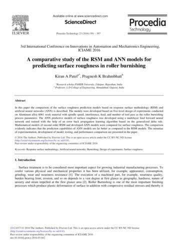
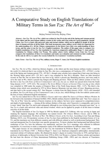
e-ISSN: 2582-5208International Research Journal of Modernisation in Engineering Technology and ScienceVolume:03/Issue:06/June-2021Impact Factor- 5.354www.irjmets.comthe efficiency, the smaller the rise in velocity caused by the propeller. If the downstream velocity is the same asthe upstream velocity. One method of modelling this effect is to use blade element theory.Blade Element Theory:By splitting each blade into a number of parts, known as blade components, the blade element theory (BET)aims to estimate the thrust of a propeller. Each variable is treated as a separate two-dimensional entity in thetheory. The aerodynamic forces can be determined based on the local flow conditions at the element using anairfoil. Then, after determining the aerodynamic properties, they are then added together to determine theproperties of the whole propeller. Propellers typically have morphing airfoil forms, which evolve over time.From a thick airfoil at the hub to a thin one at the top, the airfoil changes shape. Any such improvements can beaccommodated by blade element theory. Despite the fact that approach plans must be planned with suchconceptual shifts. Only by estimating the so-called propeller-induced velocity, which changes the AOA seen bythe blade components, can the BET produce an accurate depiction of the propeller. The airspeed within thepropeller streamtube is higher than the surrounding air, which causes this effect. To explain the inducedvelocity inside the streamtube.Figure 1: blade element formulationFigure 2: rotation of propeller & air moving directionADVANCE RATIO: J V /n.DPROPELLER EFFICIENCY:ᶯP J. C / CTPTHRUST COEFFICIENT: CT T / ρ. n2. D4TORQUE COEFFICIENT: CQ Q / ρ.n2 .D5POWER COEFFICIENT: CP P / ρ. n3 .D5II.LITERATURE SERVEYThe computational techniques used in the present work for the measurement of thrust, power and torque forthe ducted and unducted propellers using k-epsilon turbulence model. Using the thrust, power and torquemeasurements, we compare the basic theories involved with ducted and unducted propeller to the behavior ofvarious parameters like pressure, velocity contours been presented. Further, the thrust, torque and powercharacteristics has been studied for the development of ducted and unducted propeller.A propeller can be thought of as a spinning wing that assembles airfoils into a single unit, similar to the crosssection of an airplane's wing. A simple propeller configuration consists of at least two blades connected by acentral hub.Earlier Stipa (1931) and Kort (1934) were the first to propose ducted propellers, and they are often used onvessels with high thrust requirements in the low speed range. The flow characteristics of the ducted propulsionsystem as a whole. The connection between the duct and the propeller is very intense.The works of Abdel-Maksoud and Heinke (2002) and Krasilnikov et al. (2007) concluded, based oncomprehensive RANSE computations, that the scale effects on the characteristics of ducted propulsiongeometry (duct form and blade) affects propellers duct profile as well as loading conditions.Propeller efficiency can be determined using a variety of methods, including experimental and numericalanalysis. The propeller blade is tested in a wind tunnel for both static and advancing flow conditions in thewww.irjmets.com@International Research Journal of Modernization in Engineering, Technology and Science[882]
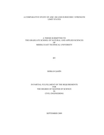
e-ISSN: 2582-5208International Research Journal of Modernisation in Engineering Technology and ScienceVolume:03/Issue:06/June-2021Impact Factor- 5.354www.irjmets.comexperimental process. Numerical analysis, on the other hand, employs a three-dimensional approach.Simulation of computational fluid dynamics (CFD) using the Reynolds-average Navier–Stokes equation (RANS)equation. For propeller design and analysis, CFD methods have grown in importance and utility.Over the last few decades, the production and use of unmanned aerial vehicles (UAVs) has exploded. As a result,it's critical to look into propeller performance to ensure that the design has resulted in a consistent UAVperformance.Benini conducted a study to compare the methods for determining propeller blade performance, includingcombined momentum-blade element theory and completely three-dimensional numerical RANS using CFDFluent. The result demonstrates that the numerical approach used produces consistent results regardless of theadvance ratio, with a maximum difference of 5% as compared to experimental results.III.METHODOLOGYPreliminary Design Analysis:In this paper, we have used NACA 24012airfoil for the designing of propeller blade. We have done somepreliminary analysis of airfoil and its corresponding propeller blade using Qblade software. Fig-3 shows theprofile of airfoil used in the propeller. The airfoil data taken from the online sources named AIRFOIL TOOLS.Figure 3: airfoil profile of NACA 24012The aerodynamic performance curves for this airfoil at a velocity of 15m/s i.e. Reynolds number 27000 at 6.5degree AOA which is usually this is airfoil section at 75% of propeller blade from hub. The propeller bladeshown in figure 3.5 is created in Qblade inbuilt design environment using the above NACA 24012 airfoilthrough it, blade is divided in to 10 sections and the data of the sections are tabulated in Table-1. The cl, cd, cmvs 6.5 degree AOA of blade section at 75% of the blade. The plots are generated in Qblade airfoil analysisenvironment as shown in figures below.The blades is aligned with a maximum thickness location i.e. Thread at centerline maximum thickness. Theblade has twist of 35 degrees at hub and 8 degrees twist at tip of the blade. Since the Qblade is a preliminarydesign tool it will design only blades leaving empty space at hub with diameter of hub between the hubportions of blades.The resulted propeller blade with a hub radius of 10mm shown in fig-7.The simulation performed using QLLT the nonlinear lifting line simulation. Further, the blade inputs are givensuch that blades rotated at 6000RPM is simulated at wind speed of 15m/s at 10% turbulence intensity with aground effect, gravitational effect at a height 250m above sea-level illustrated in fig-8.The preliminary analysis results found to be that it has a thrust of around 4.1N and a torque of 0.08764 N-m.www.irjmets.com@International Research Journal of Modernization in Engineering, Technology and Science[883]
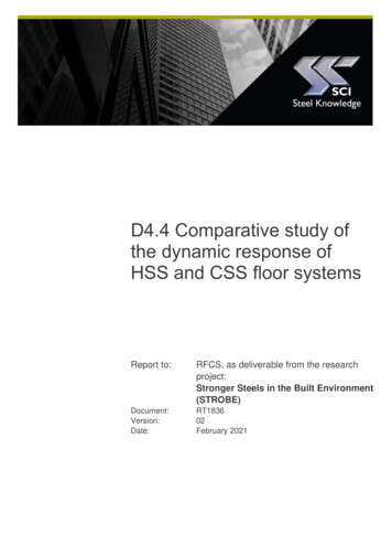
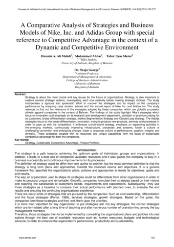
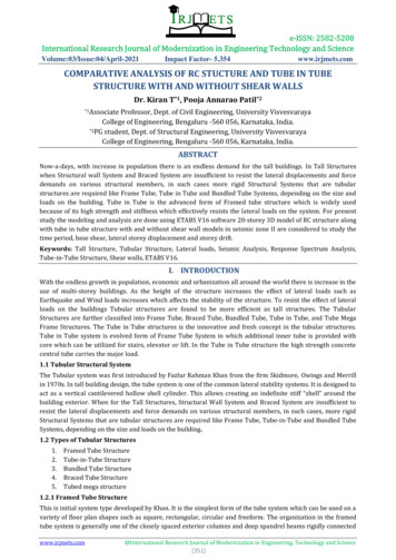
e-ISSN: 2582-5208International Research Journal of Modernisation in Engineering Technology and ScienceVolume:03/Issue:06/June-2021Figure 4: Cl vs AOAImpact Factor- 5.354Figure 5: Cd vs AOATable 1: propeller blade span wise sections detailswww.irjmets.comFigure 6: Cm vs AOAFigure 7: propeller design modelled in QbladeFigure 8: simulation of propeller in a wind turbulence model using QbladePropeller ModelAs a result, the propeller is used as the reference configuration in this study since it is one of the mostcommonly used blades for UAVs. Analysis is performed on the ducted and unducted propeller with propellerdiameter of 266.4mm at a velocity of 15m/s i.e. at a Reynolds number of 27000. Both the ducted propeller andunducted propeller modelled in CATIA as per the table-1 as shown in fig-11 and fig-10 respectively. Duct usedin this paper is decelerating duct.Figure 9: duct profilewww.irjmets.com@International Research Journal of Modernization in Engineering, Technology and Science[884]
e-ISSN: 2582-5208International Research Journal of Modernisation in Engineering Technology and ScienceVolume:03/Issue:06/June-2021Impact Factor- 5.354Figure 10: unducted propeller modelled in CATIAwww.irjmets.comFigure 11: ducted propeller modelled in CATIAThe profile of the duct used is shown in the Fig-9:.with a leading edge lip diameter of 12mm.Numerical SetupComputational Domain around the propeller geometry has created using ANSYS DESIGN MODELER 19.1. CFD ofthe both ducted and unducted propeller is done by using sliding mesh approach using ANSYS fluent 19.1. Thecomputational domain of both ducted and unducted propeller is shown in the fig-13 &12.Inside the computational domain, the small cylinder over the propeller is used as rotating domain and the outercylinder is stationary domain. In sliding mesh approach we define propeller as a stationery wall. The interfacebetween the outer and inner cylindrical domain should be matched in terms of faces so that computation setupis done. Both the domains are defined as fluid and the propeller is defined as stationary wall.Figure 12: computational domain of unducted propeller Figure 13: computational domain of ducted propellerIn ANSYS 19.1, a mesh tool was used to build the grid. The grid is important because it represents the geometryof interest in a unique way. The rate of convergence, the output obtained from the numerical analysis, and thecomputational time to run the analysis were all directly affected by the consistency of the computational grid.The meshing details of the computational domains are shown the tables below. In both stationary and rotatingdomains, the grid is totally tetrahedral and unstructured. The decision is based on the rationale thatunstructured tetrahedral grids can discretise complex geometries quickly and with minimal interactivity.The mesh used here in this cfd is tetrahedron mesh with a minimum length of 29 mm with a normal angle of18degrees ,and minimum curvature size of 0.29 mm. The mesh has a growth rate of 1.2 with a maximum sizingof 35mm and amximum proximity size of 0.29mm. The mesh element order is linear. The inflation use aroundthe propeller with a maximum layers of 10 and its first layer thickness of 1mm normal to blade surface.www.irjmets.com@International Research Journal of Modernization in Engineering, Technology and Science[885]
e-ISSN: 2582-5208International Research Journal of Modernisation in Engineering Technology and ScienceVolume:03/Issue:06/June-2021Impact Factor- 5.354www.irjmets.comTable 2: Meshing detailsThe tetrahedon wireframe section is shown in the fig-16.the expontentially denser region init shows therotating domain which has more cells i.e. lower mesh size compared to stationary domain as it needs morerefined mesh to more accurary of propeller blade study .Boundary conditions of CFD simulations were carried out with a rotational speed of 6000 RPM in the flowconditions, the free-stream velocity of 15m/s is defined on the inlet boundary, with a turbulence intensity of10%.Figure 14: mesh of rotating domainFigure 15: mesh grid in wireframe view ofComputational domain of unducted propeller.Figure 16: cut section view of computationalFigure 17: cut section view of computationaldomain of unducted propellerdomain of ducted propellerOutflow boundary conditions were set at the flow exits downstream of the flow domain to set the turbulencestrength based on the interactive conditions on the walls, a no-slip condition has been created. To integrate therotational speed, the sliding mesh relation is assigned to the domain that encloses the propeller blade. SIMPLEmethod is applied for solving the solution.Figure 18: mesh nodes and elementsThe method is particularly well suited to the study, which necessitates the interaction of stationary and rotatingframes. Specific zones will have distinct rotational speeds assigned to them. A local frame transformation willbe performed on the interface between the two regions allowing one zone's flow vector to be used byneighboring zones. The propeller blade and hub walls were also designated as rotational, with zero velocity inwww.irjmets.com@International Research Journal of Modernization in Engineering, Technology and Science[886]
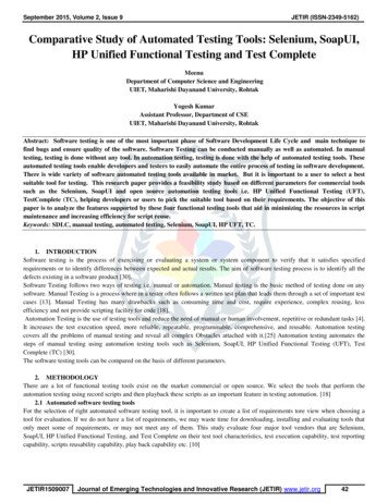
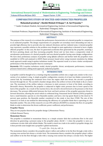
e-ISSN: 2582-5208International Research Journal of Modernisation in Engineering Technology and ScienceVolume:03/Issue:06/June-2021Impact Factor- 5.354www.irjmets.comrelation to the adjacent cell zone. A Semi-Implicit Method for Pressure-Linked Equations is used to achieve thepressure–velocity coupling (SIMPLE).Momentum and pressure were calculated using the Second Order Upwind scheme. The gradients werecalculated using the First Order Upwind for Turbulent Kinetic Energy and Turbulent Dissipation Rate, as well asthe Least Square Cell-based Algorithm. For this, first-order algorithms generated accurate results.The stationary region's inlet, outlet, and outer boundaries are far enough away from the propeller to preventthe complete production of the upstream and downstream flow from influencing the analysis' performance.The rotating domain is subdivided into a global stationary domain and a subdivided rotating field. The rotatingdomain is defined by a small cylindrical domain that completely encloses the propeller blades and hub. CFDsimulations were run with a fixed rotational speed of 6000 RPM in the flow conditions. The free-stream velocityof 15m/s is defined on the inlet boundary, with a turbulence intensity of 10%. At the flow exits downstream ofthe flow domain, outflow boundary conditions were set. On the walls, a no-slip condition has been created. Thesliding mesh reference is assigned to the domain that encloses the propeller blade in order to integrate therotational speed. The inlet type is velocity inlet, outlet is pressure outlet and the walls are no slip stationarywalls with a roughness of 0.5mm.IV.RESULTSTo check the effect of the duct and the accuracy of the obtained data, the computational analysis results ofducted propellers were compared to unducted propeller data. The torque and thrust comparison is shown inthe below table.Propulsion TypeThrustTorqueUnductedpropeller3.478N0.1896 N-mDucted propeller4.12N0.112 N-mTable-3: thrust and torqueThe velocity and pressure contours is shown in the below figures.The propeller blade's pressure contour while running at an advance ratio of J is equal to 0.0093. The pressureat the back-side of the propeller is significantly higher than the pressure at the front-side of the propeller, asseen in the diagram. Thrust is generated when the pressure differential between the front and back sides of thepropeller creates force in the forward direction.Figure 19: velocity contour over propellerFigure 20: pressure contour over top surface of propellerThe comparative analysis of both pressure and velocity contours of both unducted and ducted propeller showsthe p thrust produced by the ducted propeller is more than the unducted propeller at low flow free streamvelocity conditions. Due to positive torque produced by the propellers in both the cases it is found that thismodel is optimally efficient at their own pace. Under same boundary conditions applied for the conventionaland ducted propeller .It is found from the results that using the duct the overall thrust of the propulsive systemis increased by 18.46%.www.irjmets.com@International Research Journal of Modernization in Engineering, Technology and Science[887]
e-ISSN: 2582-5208International Research Journal of Modernisation in Engineering Technology and ScienceVolume:03/Issue:06/June-2021Impact Factor- 5.354Figure 21: pressure contour of ducted propellerFigure 22: velocity contour of ducted propellerFigure 23: pressure contour of unducted propellerV.www.irjmets.comFigure 24: velocity contour of unducted propellerDISCUSSIONThe basic k-epsilon turbulence model is better suited to low Reynolds number aerospace applications. Inaddition, the model was able to predict the transformation model and improve the model's accuracy. At anadvance ratio of J 0.0093, the pressure contour of the propeller blade is seen. The pressure at the back-side ofthe propeller is significantly higher than the pressure at the front-side of the
The aim of this research is to use CFD software (FLUENT) to simulate the flow of a propeller blade in order to determine the thrust coefficient, power coefficient, and performance. . The torque and thrust compariso